Introduction
This workshop will introduce you to Thread in the SimpleLink™ CC13x2 and CC26x2 Software Development Kit (SDK). You should have a basic understanding of the C Programming Language and some experience with embedded software development.
This lab consists of 3 tasks and one optional task. It is expected to take about 1 hour.
Thread is a low power, low data rate IPv6 based mesh networking solution designed for home automation. OpenThread is an open-source implementation of the Thread Networking Protocol released by Nest. TI-OpenThread is a Thread implementation based on OpenThread within the SimpleLink Ecosystem.
This workshop aims to give an overview of Thread in the SimpleLink CC13x2 / CC26x2 SDK and familiarize you with developing application within the SimpleLink Ecosystem.
Prerequisites
Software
CCS version 10.1 or later with support for CC13xx/CC26xx devices installed
(Optional) terminal program
Hardware
- 2x LaunchPads of either
Recommended Reading
It is recommended to get familiarized with the Thread Specification.
It is recommended to read the TI-OpenThread User's Guide alongside this lab for details and further information
Getting started – Desktop
Install the SimpleLink CC13x2/CC26x2 SDK.
Install Code Composer Studio. These instructions assume that you install CCS with support for the CC13xx and CC26xx devices.
Task 1 – Build and Flash the CLI
The first task is to simply run the Command Line example application on the two LaunchPads.
Attention
The steps in this lab make reference to CC26x2R1 LaunchPad. Please note that the same steps apply when using either boards listed under required hardware.
Import in CCS Desktop
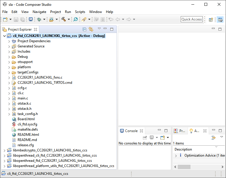
To import the CLI FTD Example Project from the SimpleLink SDK, open Code Composer Studio with an empty workspace and follow these steps.
Select
Project→Import CCS Projects...to open the import dialog.Browse to
<SDK_INSTALL_DIR>/examples/rtos/<BOARD>/thread/as the search directory.<SDK_INSTALL_DIR>is the install location of the SimpleLink SDK.<BOARD>must correspond to the board being used.
Select the
cli_ftd_<BOARD>_tirtos_<TOOL>project, where<BOARD>and<TOOL>are the development board and toolchain you are using. ClickFinishto import the example application
CCS will then import the CLI FTD example project and all dependent projects.
This will include library projects to build the OpenThread core, CLI library,
diagnostics and utilities, and more. The library projects begin with lib*, the
example project (in the figure below, cli_ftd) will build the necessary
library projects in the workspace.
Connect the LaunchPad
Start by making sure your kit is assembled, turned on, and is connected to the PC via the USB cable.
When the LaunchPad is connected, the Windows Device Manager (Start →
Control Panel → Device Manager) should show you something like the
following image
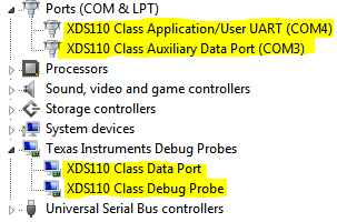
The COM port labeled Application/User UART is the UART back channel from the
XDS110 debugger. This is connected to the UART on the target device, and will
be used for our purposes.
On a unix system, these ports will show up as /dev/tty* (usually
/dev/ttyUSB* or /dev/ttyACM*). The lower numbered one is usually the
USB-to-UART back channel.
Configure the debugger connection
The example application is setup to use the correct target configuration. If you have only one XDS110 connected to your computer CCS will select that target by default. If you have more than one XDS110 connected CCS will prompt you which target you want to use when you start a debug session.
If CCS prompts you to select a debug probe, CCS will write the XDS serial number in the target configuration. You may wish to add/remove/modify the serial number in the target configuration to ensure that one LaunchPad is selected as the target for a debug session.
Follow the steps below with only one debugger connected.
Open the file
targetConfigs/CC2652R1F.ccxmlfrom the project explorer.Ensure that the connection is
XDS110 USB Debug Probe.Click on
Target Configuration.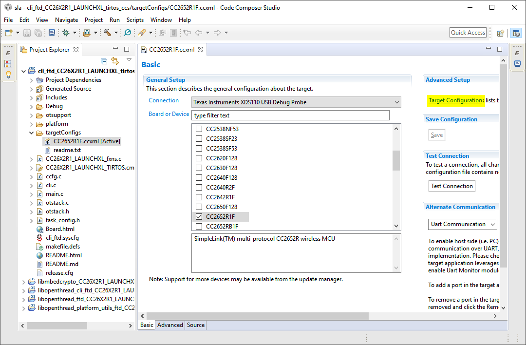
Click on the top-level node
XDS110 USB Debug Probe.For the
Debug Probe SelectionselectSelect by serial numberStart command prompt and use
xdsdfu.exeto enumerate the connected debugger. A windows example can be seen below with the serial number1000FF01.Insert the serial number.
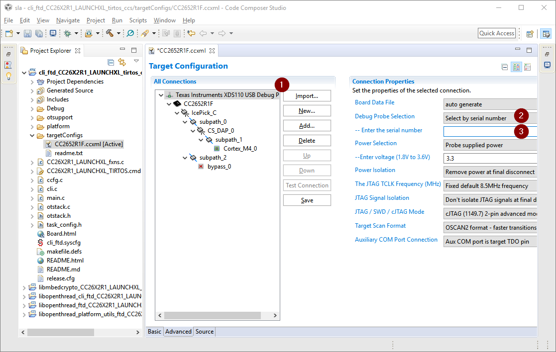
Save the settings.
Test the connection.
C:\> cd C:\ti\ccs\ccs_base\common\uscif\xds110
C:\ti\ccs\ccs_base\common\uscif\xds110> xdsdfu.exe -e

USB Device Firmware Upgrade Utility
Copyright (c) 2008-2015 Texas Instruments Incorporated.  All rights reserved.

Scanning USB buses for supported XDS110 devices...


<<<< Device 0 >>>>

VID: 0x0451    PID: 0xbef3
Device Name:   XDS110 with CMSIS-DAP
Version:       2.3.0.4
Manufacturer:  Texas Instruments
Serial Num:    0000FF01
Mode:          Runtime

Found 1 device.
You can also use xdsdfu to change the serial number.
C:\> cd C:\ti\ccs\ccs_base\common\uscif\xds110
C:\ti\ccs\ccs_base\common\uscif\xds110> xdsdfu.exe -m

USB Device Firmware Upgrade Utility
Copyright (c) 2008-2015 Texas Instruments Incorporated.  All rights reserved.

Scanning USB buses for supported XDS110 devices...


<<<< Device 0 >>>>

VID: 0x0451    PID: 0xbef3
Device Name:   XDS110 with CMSIS-DAP
Version:       2.3.0.4
Manufacturer:  Texas Instruments
Serial Num:    BADEABBA
Mode:          Runtime

Switching device into DFU mode.

C:\ti\ccs\ccs_base\common\uscif\xds110> xdsdfu.exe -s ABCDEF01 -r

USB Device Firmware Upgrade Utility
Copyright (c) 2008-2015 Texas Instruments Incorporated.  All rights reserved.

Scanning USB buses for supported XDS110 devices...

Setting serial number to "ABCDEF01"...
Build the projects and Flash the device
We need to build the CLI FTD project and flash it on both LaunchPads.
Build the CLI Project (
cli_ftd) by doing one of the following:Right clicking on the project in the project explorer and selecting
Build
Project
Clicking
Project→Build ProjectClicking the hammer icon
Ctrl + B
Build Time
By default, the TI-OpenThread example applications build with the highest optimization possible. This result in long build times due to extra steps at link time.
The build time can be significantly reduced at the cost of increased code size by setting the optimization from highest level to the second highest level. This is configured under
Project→Build→Compiler→Optimization.Debug the CLI example project by doing one of the following:
Right clicking on the project in the project explorer and selecting
Debug As→Code Composer Studio Debug SessionClicking
Run→DebugClicking the green bug icon
F11
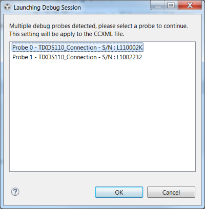
If you have multiple debug probes are connected to your computer, CCS will prompt you to select one. This serial number will be set as the debug connection for this target configuration. See the instructions above if you wish to change this later.
Once the debug session has flashed the device, the debugging session should halt a
main(). Allow the example application to free run by:Clicking
Run→ResumeClicking the green resume button
F8
End the debugging session by clicking the red stop button.
Select the second XDS Debug Probe for as the active debug probe. This can be done by following the instructions above to set the target configuration's serial number, or by unplugging the LaunchPad you just programmed. This will make CCS prompt you again to select a Debug Probe.
Debug the CLI example project on the second LaunchPad.
Allow the example application to free run as done with the first example.
Once both LaunchPads have been programmed, connect both to your computer and open a terminal program to each of the LaunchPad's Data Ports.
Connect a terminal program
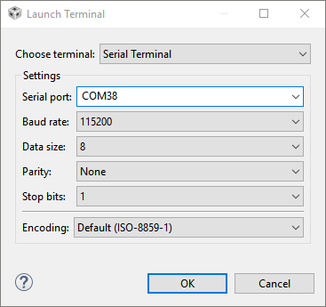
To interact with the Command Line Interface example you need to open a terminal
emulator. This can be the terminal emulator you installed earlier (PuTTY, Tera
Term, etc.) or you can use Code Composer Studio by pressing Ctrl + Shift +
Alt + T and selecting Serial Terminal.
Set your terminal emulator settings to 115200 baud rate, 8 bit data, 1 stop
bit, no parity, and no flow control.
To make sure that your terminal emulator is working with the CLI example, press
Enter while the emulator is selected. This should display the > command
line prompt.
Task 2 – Form a Thread Network
Let's create a basic network between two CLI example applications. This task will take advantage of the default Network parameters in the Thread stack. Later we will discuss how these parameters are discovered in final products.
Start a Singleton network with the first CLI example.
Press
Enterto see a prompt>.Use the
channelcommand to set the desired channel.> channel 14 Done >Terminal 1
Use the
panidcommand to set the PAN ID.> panid 0xface Done >Terminal 1
Use the commands
ifconfig upandthread startto start the Thread stack. And use thestatecommand to see the change in device status from detatched to the leader of the network.> ifconfig up Done > thread start Done > state detached Done > state leader Done >Terminal 1
This device is now the leader of a new Thread Partition. Connect to this new Thread network with the second LaunchPad.
Press
Enterto see a prompt>.Use the
scancommand to make sure that this LaunchPad can see the first one.> scan | J | Network Name | Extended PAN | PAN | MAC Address | Ch | dBm | LQI | +---+------------------+------------------+------+------------------+----+-----+-----+ > | 0 | OpenThread | dead00beef00cafe | face | 9e782c4394ca339f | 14 | -63 | 61 | Done >Terminal 2
The following prompt may be swallowed up by the output of the scan, press
Enterto get the prompt again.Use the
channelandpanidcommands as in the first example to set the same channel and PANID.> channel 14 Done > panid 0xface Done >Terminal 2
Use the
ifconfig upandthread startcommands to start the Thread stack. And use thestatecommand to see the change in device status as the node becomes a child of a router in the network> ifconfig up Done > thread start Done > state child Done >Terminal 2
Now that the two Thread devices are connected, you can ping between them. Use
the ping command on one of the CLI examples to send an ICMPv6 Echo Request to the Realm-Local All Nodes
multicast address, ff03::1. This will result in all IPv6 nodes within realm
scope of the device (currently only the other CLI example) to respond with an
ICMPv6 Echo Response.
> ping ff03::1
> 8 bytes from fe80:0:0:0:f423:af0:300:b057: icmp_seq=1 hlim=64 time=37ms

>
Terminal
You now have a working Thread network up and running between two CLI devices. But, this relied on the default values from OpenThread, like the Extended PAN ID, network name, and Thread master key; and it relied on you selecting the correct channel and PAN ID. This is not advantageous for an end product; you cannot guarantee that every device will be based on Texas Instrument devices, or that they chose the same channel and PAN ID to operate on.
Thread commissioning offers a mechanism to bring new devices securely into your network without them having any previous knowledge of your network.
Task 3 – Commission a Device
Commissioning is the process of bringing an unconfigured/untrusted device securely into a Thread Network. Thread splits joining a Thread network (shown in the previous task) and Commissioning. This split is because of the large cryptographic overhead of the Commissioning process. This allows Thread devices to be commissioned out-of-band if they do not support the necessary crypto primitives.
The Thread specification details the commissioning process, but at a high level the process is as follows:
Commissioner becomes active commissioner on the network.
Commissioner is informed of the new joiner's information.
Commissioner notifies the network of the prospective joiner.
Joiner scans for the Thread network.
A Router responds to the Joiner's Discovery Request. This router is now designated the Joiner Router.
The Commissioner and Joiner establish a DTLS session through the Joiner Router using the pre-shared information.
The Commissioner authenticates the Joiner and instructs the Joiner Router to disseminate the network information. The Commissioner and Joiner DTLS session is destroyed.
The Joiner Router uses an ephemeral key to securely send the network information to the Joiner.
We are now going to use our two CLI example applications to illustrate the commissioning process.
Reset both devices. We are now going to start a singleton network with the first CLI example as you did in the previous task, but this time we are going to change the Thread Master Key to show the network information being disseminated.
Press
Enterto see a prompt>.Use the
masterkeycommand to change the Thread master key from its default value.> masterkey ffeeddccbbaa99887766554433221100 Done >Terminal 1
Use the
channelcommand to set the desired channel.> channel 14 Done >Terminal 1
Use the
panidcommand to set the PAN.> panid 0xface Done >Terminal 1
Use the commands
ifconfig upandthread startto start the Thread stack.> ifconfig up Done > thread start Done > state detached Done > state leader Done >Terminal 1
This device is now the leader of a new Thread Partition. Since it is the only device in the network, it will be used as the Commissioner.
For this task we are going to use PPSSKK as the PSK. We
need to know the joining devices' EUI64
(the unique identifier of this joiner device). On the second LaunchPad, use the
eui64 command to discover the Joiner's EUI64.
> eui64
00124b001314e882
Done
>
Terminal 2
Now on the first LaunchPad, we are going to setup the commissioner and add a joiner entry for our new device.
Use the
commissioner startcommand to start the commissioner.> commissioner start Done >Terminal 1
Use the
commissioner joinercommand to add a joiner entry with the discovered EUI64 and PSK.> commissioner joiner add 00124b001314e882 PPSSKK Done >Terminal 1
Check your EUI64
The EUI64 of your prospective joiner will be different than this example.
The commissioner now knows of the device that will be petitioning the network. Now setup the Joiner to petition the network.
Use the
masterkeycommand to make sure that the Thread master key is set to the default value.> masterkey 00112233445566778899aabbccddeeff Done >Terminal 2
Use the
ifconfig upcommand to bring up the interface.> ifconfig up Done >Terminal 2
Use the
joiner startcommand to start the joining process. The joiner will start negotiating a DTLS session and authenticate with the commissioner. This process will take a few moments. When the join has finished, the CLI will print outJoin Success.> joiner start PPSSKK Done > Join Success >Terminal 2
Use the
masterkeycommand to make sure that the Thread Network information has been disseminated.> masterkey ffeeddccbbaa99887766554433221100 Done >Terminal 2
Use the
thread startcommand to start the Thread stack.> thread start Done > state child Done >Terminal 2
The second LaunchPad has now been securely added to the Thread Network. Don't
forget to stop the commissioner on the first LaunchPad with the commissioner
stop command. You can now interact with the other Thread devices like before
with the ping command.
> ping ff03::1
> 8 bytes from fe80:0:0:0:f423:af0:300:b057: icmp_seq=1 hlim=64 time=37ms

>
Terminal
Don't forget to stop the commissioner on the first LaunchPad.
> commissioner stop
Done
>
Terminal 1
Task 4 (optional) – Add a Ping Handler
Until this point we have been assuming that the device we are pinging has gotten the ICMPv6 packet because our CLI has gotten a response. We should add some physical indication that the device has received an ICMPv6 packet.
In this task we are going to add an ICMPv6 handler to the CLI FTD example project. This handler will see that the ICMPv6 packet is an echo request and will toggle an LED GPIO.
We will be adding our new handler to the application source file. Open
cli.cin the CLI FTD project from the Project Explorer on the right.We will be using
memsetfrom the standard library and ICMPv6 interfaces from OpenThread. We need to add includes for the standardstring.hheader and OpenThread'sicmp6.hheader.#include <openthread/config.h> #include <openthread-core-config.h> /* Standard Library Header files */ #include <assert.h> #include <stddef.h> #include <string.h> // <<< ADD: for memset /* POSIX Header files */ #include <sched.h> #include <pthread.h> #include <unistd.h> /* RTOS Header files */ #include <ti/drivers/GPIO.h> /* OpenThread public API Header files */ #include <openthread/cli.h> #include <openthread/instance.h> #include <openthread/icmp6.h> // <<< ADD: ICMPv6 interface /* OpenThread Internal/Example Header files */ #include "otsupport/otrtosapi.h" #include "otsupport/otinstance.h" /* Example/Board Header files */ #include "task_config.h" #include "Board.h"cli.c: header includes
Include convention
By convention, example applications use
"delimiters for local includes (same folder or same project) and<>delimiters for library includes (along the search path).Now we add the
otIcmp6Handlerstructure to our global static variables. This structure will be used to register the handler later with OpenThread./* Application thread */ void *cli_task(void *arg0); /* Application thread call stack */ static char cli_stack[TASK_CONFIG_CLI_TASK_STACK_SIZE]; /* === BEGIN ADD === */ /* ICMPv6 Handler struct registered with OpenThread. */ static otIcmp6Handler cli_icmpHandler; /* === END ADD === */cli.c: global variables
Create the handler to process handling ICMPv6 messages. This will be registered with OpenThread later. Define this before
cli_task(.)./* === BEGIN ADD === */ /** * Handler for ICMPv6 messages. */ void cli_icmp6RxCallback(void * aContext, otMessage * aMessage, const otMessageInfo *aMessageInfo, const otIcmp6Header *aIcmpHeader) { (void)aContext; (void)aMessage; (void)aMessageInfo; if (OT_ICMP6_TYPE_ECHO_REQUEST == aIcmpHeader->mType) { GPIO_toggle(CONFIG_GPIO_GLED); } } /* === END ADD === */cli.c: cli_icmp6RxCallback()
Initialize the handler structure to
0. Add the function pointer to the handler structure. And finally register the handler with OpenThread./** * Main thread starting the CLI example within OpenThread. */ void *cli_task(void *arg0) { // ... /* === BEGIN ADD === */ /* setup ICMPv6 handler. */ memset(&cli_icmpHandler, sizeof(cli_icmpHandler), 0U); cli_icmpHandler.mReceiveCallback = cli_icmp6RxCallback; OtRtosApi_lock(); otIcmp6RegisterHandler(OtInstance_get(), &cli_icmpHandler); OtRtosApi_unlock(); /* === END ADD === */ while (1) { sleep(2); /* ignoring unslept return value */ GPIO_toggle(CONFIG_GPIO_RLED); } }cli.c: cli_task()
API lock
OpenThread is written with the assumption that it and its APIs are called within a single-threaded architecture. Since the
cli_taskis in a different thread context than theot_task, we ensure coherency by locking the API mutex. Consult the TI-OpenThread User's Guide for more information on this.Start a debug session with the new code. Don't forget to run the example.
Setup a Thread network by following the instructions in either Task 2 or Task 3.
Observe that the Green LED on the LaunchPad toggles when you send a ping.
You have now successfully added a handler for ICMPv6 messages. Be careful using ICMPv6 messages, their usage is defined in RFC 4443. An RFC is the way the IETF develops standards. Ratified RFCs govern most of the traffic over the Internet.
Further Reading
It is recommended that you read the Developing Thread Applications chapter of the TI-OpenThread User's Guide for more information on the software development environment.
Familiarize yourself with the TI-OpenThread APIs and OpenThread APIs.
Consider looking at the RFCs that define UDP (RFC 768) and CoAP (RFC 7959).
This work is licensed under a Creative Commons Attribution-NonCommercial-NoDerivatives 4.0 International License.