Introduction
This module is an introduction to the Real Time Localization System (RTLS) Toolbox as well as its suite of PC tools. The RTLS toolbox is a collection of tools for localization, direction finding, and secure range bounding.
The RTLS architecture consists of software running on the host (PC) and the embedded device (CC26xx). Embedded RTLS nodes are controlled by the host via commands over UART. Host software is responsible for sending commands to the embedded nodes and collecting the results. The suite of host software is referred to as the RTLS Node Manager.
It is assumed that the reader has a basic knowledge of embedded tool chains and general C and Python programming concepts.
This lab is based on the rtls_master rtls_slave and rtls_passive projects
that are part of the SimpleLink™ CC2640R2 SDK
(http://www.ti.com/tool/SIMPLELINK-CC2640R2-SDK).
This lab will focus on running the out of box demos, setting up the host Python environment, and getting started with data collection using Angle of Arrival (AoA) or Time of Flight (ToF).
Prerequisites
Software for desktop development
- SimpleLink™ CC2640R2 SDK (http://www.ti.com/tool/SIMPLELINK-CC2640R2-SDK)
- Those listed under the Dependencies section of the CC2640R2 SDK Release Notes
- Python 3.7 or higher
- Git bash
- RTLS known issues page on E2E. Apply all relevant fixes from this page.
Hardware
This module requires the following kits:
- 3x CC2640R2-LAUNCHXL
- 1x BOOSTXL-AoA
Recommended reading
These chapters in the TI BLE-Stack User's Guide
- Getting Started
- The CC2640R2F SDK Platform
- Application
- BLE-Stack
- RTLS Toolbox
- Network Processor Interface (NPI)
Getting started with AoA booster pack
Project readme files:
- rtls_master
- All relevant information to
rtls_slaveandrtls_passiveare contained in thertls_masterreadme rtls_agentReadme located in <SimpleLink CC2640R2 SDK> → tools → blestack → rtls_agent folder within the CC2640R2 SDK. This will be covered in detail in Task 2.
Getting started – Desktop
Install the Software
- Run the SimpleLink CC2640R2 SDK installer.
- Install Python 3.7 or later from Python Download page.
- Setup Python environment as described in the README.html in the <SimpleLink CC2640R2 SDK> → tools → blestack → rtls_agent folder.
- If a bash environment doesn't exist on your system, install Git bash
This gives you:
- The SDK with TI-RTOS included at
<SIMPLELINK_CC2640R2_SDK_INSTALL_DIR>which defaults toC:\ti\simplelink_cc2640r2_sdk_x_xx_xx_xx. - Python 3.7 environment with all dependencies required by the RTLS Node Manager
Modify/Load the software
- Load Board #1 + BOOSTXL-AoA with
rtls_passiveproject:
<SimpleLink CC2640R2 SDK> → examples → rtos → CC2640R2_LAUNCHXL → blestack → rtls_passive - Load Board #2 with
rtls_slaveproject:
<SimpleLink CC2640R2 SDK> → examples → rtos → CC2640R2_LAUNCHXL → blestack → rtls_slave - Load Board #3 with
rtls_masterproject:
<SimpleLink CC2640R2 SDK> → examples → rtos → CC2640R2_LAUNCHXL → blestack → rtls_master
Building the projects
Be sure to build both the stack and application before loading projects.
Note that the rtls_passive uses the micro BLE-Stack setup as a connection
monitor, therefore it does not have a separate stack project.
The following tasks will show you how to get started with data collection using the RTLS toolbox. This lab will focus on the RTLS Toolbox as a whole and the Python based PC environment. Subsequent labs will cover AoA or ToF specific topics.
Localization Techniques
A Real Time Localization System can be defined as a system capable of determining the position of a target within a defined physical area in real time. The physical area is normally defined through deployment of reference/locator nodes.
There are two fundamentally different approaches to location finding:
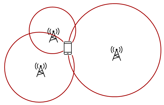
Trilateration, where you know the distance between a reference node and a
target node Time of Flight gives you the distance from the receiver to the transmitter.
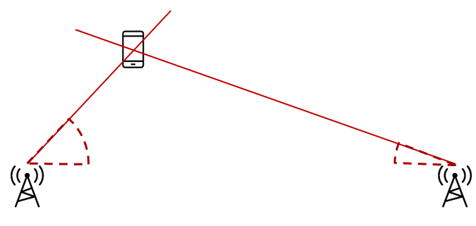
Triangulation, where you know the direction from a reference node to a target
node Angle of Arrival is a technique that can be used to measure the angle
from the receiver to the transmitter.
What is a node?
A node in this case is referred to as a localization capable embedded device. For the demos in the SDK, nodes are LaunchPads
RTLS Toolbox Introduction
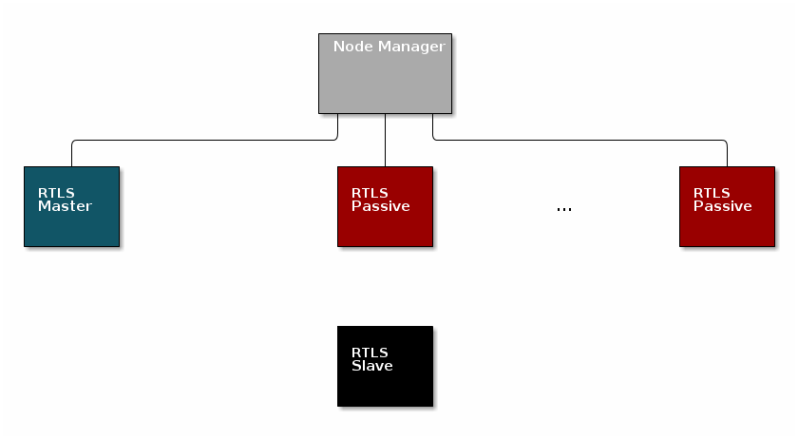
In the Localization Techniques, we discussed how multiple AoA nodes can combine angle information to perform triangulation and how multiple ToF nodes can combine distance information to perform trilateration. It is important to remember in the pictures above, it is not possible for one single node to localize an object using the TI sample applications. A single AoA node only produces an angle, and a single ToF node only produces a distance. These by nature, are ambiguous measurements. If there are at least two nodes providing AoA or ToF data, then localization can occur. This requires a fourth device that is capable of combining the samples from the individual nodes and finding the intersection.
The intersection between the angles (AoA) or circles (ToF) is the estimated location of the device. An overview of the topology is shown below. In the diagram below, the black, blue, and red boxes represent CC2640R2 LaunchPads while the grey box is a PC.
Time of Flight performs which of the following localization techniques?
The RTLS toolbox is a collection of software that is purposed for the localization use case. A table below summarizes each software component in the toolbox as well as its applications for localization. The software components below will run on the embedded nodes.
| Software Component | Usage |
|---|---|
| BLE-Stack | Advertising, scanning, connection, exchanging RTLS data |
| Connection Monitor | Follows a BLE connection using Micro BLE-Stack |
| Angle of Arrival | Radio patches and driver to read AoA data embedded in BLE packets |
| Time of Flight | Radio patches and driver to send, receive, and observe ToF exchange |
| Unified Network Processor Interface (UNPI) | A serial protocol including packet format and handshaking for power savings |
| RTLS Control Module | Implements the command and event set used to communicate RTLS information between devices. This runs on the embedded devices and translates UNPI frames into the necessary AoA and ToF function calls |
The software components in the following table run on a PC. TI has setup a PC based environment to facilitate in evaluating and prototyping various RTLS algorithms. Once the algorithms are complete, the various PC components above can be migrated to an embedded device. See the Central Processing Node section for more information.
| Software Component | Usage |
|---|---|
| RTLS Node Manager | Framework for sending and receiving RTLS commands and events from the embedded devices to PC. Implements higher level logic such as forwarding necessary BLE connection information to the connection monitor node. |
| Websocket Server | Implements the server side of a TCP socket. Intended to bridge serial connections over UNPI from the node manager to TI GUI composer app |
| RTLS Manager GUI Composer App | A simple GUI for aggregating and logging RTLS communication and graphing AoA or ToF data. This is Javascript based and runs in the web browser |
RTLS Roles and Topology
Each node in an RTLS network utilizes the software components listed above
in a different way to perform a specific task related to localization. These
capabilities map to a role within the RTLS network and ultimately are
implemented by sample applications within the SDK. There are three examples:
rtls_master, rtls_slave, and rtls_passive. The capabilities of these
examples are explained below. All embedded nodes implement UNPI and act as
slaves in the UNPI protocol. Additionally all embedded nodes have the RTLS
Control module implemented for processing RTLS commands from the UNPI interface.
Role combinations and possibilities
The following subsections aim to describe what localization roles are implemented by the sample applications in the SDK. This is not a comprehensive list of what is possible on each node, but rather an explanation of what the examples will do out of the box. For a list of potential combinations, please see Role Combinations.
Master
The RTLS master runs a full BLE-Stack and acts as a central device. It will scan and connect to the RTLS slave over BLE. Once a connection is established the RTLS Master will do the following:
- Share the connection parameters (access address, master sleep clock accuracy, and CRC init) with the PC.
- Use the BLE link to share ToF and AoA parameters with the peripheral device.
- Implements the ToF master role
- Does not send out AoA packets, but configures the slave to do so.
Slave
The RTLS slave runs a full BLE-Stack and acts as a peripheral device. This is the device that is to be located. The slave device will advertise and enter a connection with the RTLS Master.
- Sends data packets with AoA tone embedded using Constant Tone Extension (CTE)
- Advertises special string to be detected by
rtls_master(covered in detail in Task 3) - Implements ToF slave role
- BLE-Stack peripheral role
- Wireless/battery operated, not connected to PC
Passive
The RTLS passive does not actively participate in the BLE connection between the RTLS master and slave. Instead, it uses the Micro BLE-Stack in connection monitoring mode to follow the connection. To do this, the passive device relies on the Master to distribute the connection parameters once a connection is formed. The passive node does the following:
- Implement ToF passive role
- Receives packets with CTE and performs in-phase and quadrature component (IQ) sampling
- Uses Micro BLE-Stack in Connection Monitoring mode to follow connection between master and slave
PC/Central Processing Node
The PC node is responsible for controlling the embedded RTLS nodes by sending commands and processing events. In the SDK, this is realized by a combination of a Python layer that implements the UNPI master role and a websocket server that translates UNPI commands to a socket interface that is used by the GUI Composer application running in the browser.
This software is intended to use as a framework for extracting data from the embedded nodes and using it to prototype high level RTLS algorithms on the PC.
Implementation of PC Software
In a final product, these algorithms may be implemented on an embedded device or even perhaps the RTLS master node. TI has provided PC software to aid in data plotting and prototyping various algorithms.
The PC implements the following roles in Python:
- UNPI master
- COM port interface
- Implementation of RTLS UNPI subsystem/command set
- Websocket server
The PC implements the following roles in GUI Composer/Javascript:
- Websocket client on localhost
- Graphing and logging data from websocket
- Parsing JSON objects to extract RTLS data
- Issue commands to RTLS nodes via websocket to UNPI conversion
- Enumerate devices
- Distribute connection parameters to passives
Is it possible to have multiple RTLS passive devices in a network?
Why would multiple passive devices be desirable? (select all that apply)
Role Combinations
BLE-Stack
The Bluetooth Core Spec allows for devices to operate in various roles as well as combinations of roles. The table below shows the required and optional features for each example.
| Example Name | Central | Peripheral | Broadcaster | Observer |
|---|---|---|---|---|
| RTLS Master | R | O | O | R |
| RTLS Slave | O | R | R | O |
| RTLS Passive | No | No | O | R* |
Legend:
- R: Required
- O: Optional
- No: Not supported
Connection Monitor
The R* above denotes that while the connection monitor is capable of scanning
for beacons, it is also required that the connection monitor follow a connection.
The monitoring role is not officially defined by the Bluetooth Spec, but it is
a critical functionality in the rtls_passive.
ToF
ToF roles may be rotated between the RTLS master and RTLS passive. This is a desirable feature because it increases spatial diversity which makes the system more robust against multi-path fading. (Discussed in detail in Physical Considerations.) The following table lists valid configurations for ToF.
| Example Name | ToF Master | ToF Slave | ToF Passive |
|---|---|---|---|
| RTLS Master | R | N/A | O |
| RTLS Slave | N/A | R | N/A |
| RTLS Passive | O | N/A | R |
Legend:
- R: Required
- O: Optional
- No: Not supported
- N/A: Not applicable
AoA
The Bluetooth Core Spec defines multiple roles for both connected and connection-less AoA. The following configurations are supported by the examples in the CC2640R2 SDK.
| Example Name | Send CTE | Perform IQ Sampling |
|---|---|---|
| RTLS Master | No | No |
| RTLS Slave | R | No |
| RTLS Passive | N/A | R |
Legend:
- R: Required
- O: Optional
- No: Not supported
- N/A: Not applicable
Optional Features
In all of the tables above (AoA, ToF, BLE) features listed as optional are not implemented by the sample applications included in the SDK, but are valid and possible configurations that can be implemented by the user.
For example: rtls_master could be a multi-role device or rtls_passive could
operate as ToF master.
Physical Considerations
Before evaluating the RTLS solution, it is important to consider the environment. All radio communication protocols can be susceptible to multi-path fading, and RTLS based systems are not exempt. It is important to control the environment when evaluating or at least be aware of the potential affects of multi-path on the results.
It is recommended to evaluate the RTLS solution in an area that optimizes RF conditions. This includes:
- An open space with no large metal or concrete obstructions (pillars, poles, etc)
- Relatively few interference sources (i.e. Wi-Fi access points, etc)
- Raised platforms for the nodes made out of cardboard ~1m off the ground.
A desk environment generally has sub-optimal RF conditions and should be avoided.
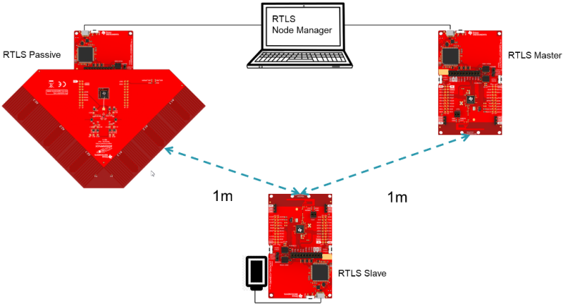
See the image below for a recommended layout of the nodes during evaluation, this is a 2D image where all devices are laying on a flat surface "pointing" as shown in the picture. In this case each node should be placed on a box so that it does not sit directly on the ground.
ToF Specific Considerations
For systems that use Time of Flight in distance mode (TOF_MODE_DIST),
it is also important to keep the rtls_slave node at a fixed distance of
1 meter during the first 1000 ToF samples. (controlled by TOF_CALIB_SAMPLES)
The node does not report distance samples before it is calibrated, so once it
starts reporting measurements, it is okay to start moving it around.
BOOSTXL-AOA and Time of Flight
When operating in Time of Flight mode (i.e. RTLS_LOCATIONING_AOA not defined),
the BOOSTXL-AoA should not be mounted on the RTLS passive. RTLS projects in
ToF mode do not initialize the pins used by the RF switches. Instead an
unmodified LaunchPad should be used. Otherwise, the physical layout should be
same.
AoA Specific Considerations
In our rtls_passive angle calculation, the angle is determined after both antenna array 1 and array 2 both get 1 AoA packet. Then we compare the RSSI values of both received packet to determine which result we should use. That means when you placed the slave at 0 degree, the uncertainty is at its highest due to the RSSI value will be pretty much the same for array 1 and array 2. For best results, use the placement above that will result in a 45 degree initial angle.
Task 1 – Running the RTLS Demo
In this task, we will use the pre-compiled websocket_server.exe located at
<SimpleLink CC2640R2 SDK> → tools → blestack → rtls_agent
It is recommended to familiarize yourself with the readme in the same folder
before starting.
Apply all fixes from the RTLS known issues page on E2E
Arrange LaunchPads as described in the Physical Layout section above.
Build the projects and flash the LaunchPads as described in Modify/Load the software
Run the pre-compiled
websocket_server.exe, it will prompt you to select the COM ports of thertls_masterandrtls_passive- Be sure to select the
Application/User UARTports. Make sure you don't have caps lock enabled. - Select both ports before hitting enter
- On connect, the
websocket_serverwill identify the RTLS nodes connected and their capabilities.
- Be sure to select the
Navigate to TI GUI Composer Gallery and search for "RTLS Monitor"
- Select the RTLS_Monitor and click on it, this will open it in the browser view of GUI composer.
Click the connect button, this will connect to the websocket_server running on localhost.
On success, you should be able to see graph window displaying sample data.
- It will take ~30 seconds before the graph starts showing data.
- We will cover more about what is happening during that time and what it takes to setup a RTLS network in Task 3.
- If evaluating in ToF mode, you should not move the nodes until the GUI starts receiving data, because ToF is calibrating. Once the GUI starts graphing, it is okay to move the nodes around.
Bonus
Define RTLS_LOCATIONING_AOA in build_config.opt (rtls_master, rtls_slave)
or preprocessor defines in project settings (rtls_passive). Repeat the steps above,
what changed?
What localization technique does the out of the box software employ?
Review the log, what devices are providing ToF distance measurements?
What is the format of the individual logs being sent between the websocket server and GUI Composer?
Assessing RTLS performance using the out of the box demos
The RTLS demos provided by TI are intended for evaluation use only and serve as a starting point for localization development. Better performance and accuracy can be achieved by utilizing the foundational demo toolkit provided by TI and developing advanced, customized algorithms to process AoA and ToF data. See the AoA and ToF specific labs for detailed information on demo results that can be used as a performance baseline as well as tips on improving performance.
The demo you have run, is not optimized for performance. It instead serves as a starting point for localization development. It is possible to achieve much better performance and accuracy than is seen here by developing advanced algorithms to process AoA and ToF data. TI is actively looking into algorithm development, and encourages their customers to do so too. This is a strong way of differentiating a localization product. See the AoA and ToF specific labs for more discussion and explanation of the results
Task 2 – Use RTLS Node Manager Directly
This task will bypass the GUI Composer application and interact directly with
the RTLS Python APIs to collect data. This gives power to the developer to define
custom behavior of the RTLS network and control the devices directly.
Specifically, this will cover setting up the required Python dependencies and
running the rtls_example.py template script described in the SDK.
Assumptions and Notation
Before starting this task the following is assumed
- A command prompt supporting bash or Git bash is open and running.
- Unix style slashes will be used throughout. If it is necessary to run these
steps in the Windows Command Prompt (
cmd.exe), then/should be replaced with\. - Various command prompts will search your System Path variable to find Python. If you have a pre-existing Python version in your path this may be selected over the newly installed version. To prevent mixing the two up, we will use virtual environments.
- We assume that Mac users don't have another instance of Python 3 installed.
If this is not the case, then based on the
PATHvariable an older version of Python may be selected with invoking thepython3command. Be sure to invoke the correct version of Python. - Here we re-hash some of the instructions from the rtls_agent/readme.html, if you already followed it, some steps may be redundant.
- Install Python per steps in Getting started
- Open a command prompt (Git Bash is recommended)
Create a Python virtual environment
- Navigate to the SDK folder (e.g.
C:\ti\simplelink_cc2640r2_sdk_x_xx_xx_xx\tools\blestack\rtls_agent) - Execute
py -3.7 -m venv .venv(windows) orpython3 -m venv .venv(mac). - This will create a folder called
.venvin the current directory that includes a copy of the python interpreter and a sandbox for installing packages. - Activate virtual environment using
source .venv/Scripts/activate(bash) or.venv\Scripts\activate.bat(Windows cmd) - Observe that when a venv is activated
(.venv)will appear before each cmd prompt - Notice that once the virtual environment is activated, the
pythoncommand will use the local Python interpreter in the venv. See Virtual Environments for more info.
- Navigate to the SDK folder (e.g.
Install required Python Dependencies into the newly created virtual environment
- Execute
python -m pip --proxy www.proxy.com install -r requirements.txt - Note that above
--proxy www.proxy.comis only required if behind a proxy. www.proxy.comis an example of a proxy. It should be replaced with the web address of your specific proxy if applicable.- This will install the required Python packages that are needed by the RTLS Python suite.
- Execute
Open the
rtls_example.py, go to line 18, and edit the linemy_nodes = [RTLSNode('COM14', 115200), RTLSNode('COM47', 115200)]to use the COM ports of the master and passive LaunchPads.Save the file and run it using
python -u rtls_example.py.- The
RTLS_CMD_IDENTIFYresponse will be listed for master and passive. - From here the code will just loop listening for messages. It can be killed with the keyboard interrupt (ctrl+c)
- See below for sample output (note that the addresses and COM ports will be different)
- The
54:6C:0E:A0:3B:4C TOF_MASTER, RTLS_MASTER
54:6C:0E:A0:58:41 CM, TOF_PASSIVE, RTLS_PASSIVE

Sending example command RTLS_CMD_IDENTIFY; responses below

{"identifier": "54:6C:0E:A0:3B:4C", "message": {"originator": "Nwp", "type": "SyncRsp", "subsystem": "RTLS", "command": "RTLS_CMD_IDENTIFY", "payload": {"capabilities": {"CM": false, "AOA_TX": false, "AOA_RX": false, "TOF_SLAVE": false, "TOF_PASSIVE": false, "TOF_MASTER": true, "RTLS_SLAVE": false, "RTLS_MASTER": true, "RTLS_PASSIVE": false}, "identifier": "54:6C:0E:A0:3B:4C"}}}
>> Got IDENTIFY from 54:6C:0E:A0:3B:4C connected to COM360. It is capable of RTLS_PASSIVE

{"identifier": "54:6C:0E:A0:58:41", "message": {"originator": "Nwp", "type": "SyncRsp", "subsystem": "RTLS", "command": "RTLS_CMD_IDENTIFY", "payload": {"capabilities": {"CM": true, "AOA_TX": false, "AOA_RX": false, "TOF_SLAVE": false, "TOF_PASSIVE": true, "TOF_MASTER": false, "RTLS_SLAVE": false, "RTLS_MASTER": false, "RTLS_PASSIVE": true}, "identifier": "54:6C:0E:A0:58:41"}}}
>> Got IDENTIFY from 54:6C:0E:A0:58:41 connected to COM358. It is NOT capable of RTLS_PASSIVE
Why is it recommended to create a virtual Python environment (select all that apply)?
Task 3 – Building Custom RTLS Python Scripts
With the environment setup, it is time for us to use Python directly to control the RTLS nodes. The goal of this task is to explain the RTLS PC software and to walk through setting up a RTLS network.
You might want to make a copy of the default rtls_example.py so it is
preserved. Save it with another name like rtls_example_old.py as a backup.
RTLS Node Manager Python Overview
First, we will briefly discuss the important layers of the Python solution and their role.
/rtls_agent
    /rtls/
        rtlsmanager.py - Class to manage multiple nodes in an RTLS network.
                         Subscribes to incoming data from the nodes, routes
                         outgoing data to each of the nodes. Distributes
                         connection parameters from master node to any
                         connected passive nodes when an connection is
                         established. Handles messages from websocket server
                         if one is provided.

        rtlsnode.py -    Class that implements the basic functionality of a node
                         in an RTLS network. This class will query the embedded
                         device connected to it and determine its capabilities.
                         Essentially this assigns a role in an RTLS context to
                         a COM port.

        ss_rtls.py       Defines the commands in the RTLS UNPI subsystem.
                         This file will define builder classes for the various
                         UNPI commands that the RTLS subsystem supports.

    /unpi/
        serialnode.py - Thread that manages serial communication from COM ports.
                        to higher layers.
                        Queues up messages and sends them to parser.
        unpiparser.py - Parser for Unified Network Processor Interface messages.
                        Implements UNPI frame format packing/unpacking.
RTLS Python Program Template
It is recommended to build RTLS based Python applications on top of the
RTLSManager class within rtlsmanager.py. Together with the the RTLSNode
class this forms the RTLS API set. The rtls_example.py from the previous task
shows how perform basic initialization of the RTLSNodes and RTLSManager and will
serve as a template for the exercises in this task.
Here we highlight some of the important parts of the example:
First, construct an instance of the RTLSNode class for the master and passive
device connected to PC. The first parameter is the user/UART COM port, and the
second is the baudrate which defaults to 115200.
my_nodes = [RTLSNode('COM14', 115200), RTLSNode('COM47', 115200)]
Instantiate the RTLSManager will the newly created nodes, but do not connect a websocket.
manager = RTLSManager(my_nodes, wssport=None)
Create a subscriber instance, and add it to the manager. Essentially this tells the manager to add messages it receives to the example programs queue to be processed. Then start the manager.
managerSub = Subscriber(queue=queue.PriorityQueue(), interest=None, transient=False, eventloop=None)
# Attach subscriber to manager
manager.add_subscriber(managerSub)
manager.start()
# Tell the manager to automatically distribute connection parameters
manager.auto_params = True
Poll the capabilities of each node, assign master and create list of passives.
timeout = time.time() + 5
while time.time() < timeout:
    if all([node.identifier is not None for node in manager.nodes]):
        try:
            masterNode = next((n for n in manager.nodes if n.capabilities.get('RTLS_MASTER', False)))
        except StopIteration:
            pass
        passiveNodes = [n for n in manager.nodes if not n.capabilities.get('RTLS_MASTER', False)]
        break
    time.sleep(0.1)
Now that we have instantiated the classes, and got the capabilities of the nodes, we are ready to create the main loop.
while True:
    # Get messages from manager
    try:
        # Pend on activity from one of the nodes with a given timeout.
        node_msg = managerSub.pend(block=True, timeout=0.05)

        # We received data from one of the nodes
        # First determine which node sent the information.
        from_node = node_msg.identifier

        # Extract the data from the message
        msg = node_msg.message.item

        # Print the message as JSON
        print(node_msg.as_json())

        # Perform further processing here.

    except queue.Empty:
        pass
RTLS Network Setup Procedure
The preceding code snippets in this task form a template program built on
top of the RTLSNode and RTLSManager classes. At this point you should have
a basic understanding of RTLS classes. Next we will cover the minimum commands
required to setup an RTLS network.
In which Python file would you find the UNPI command definitions for the ToF?
The embedded examples in the SDK will synchronize localization measurements on a
connection. In this case a measurement can be ToF interleaved with the BLE
connection events or AoA measuring the CTE embedded in the connection packets.
In both cases a BLE connection is a prerequisite for performing localization.
The sequence diagram below shows the UNPI commands required to establish a
connection between rtls_master and rtls_slave.
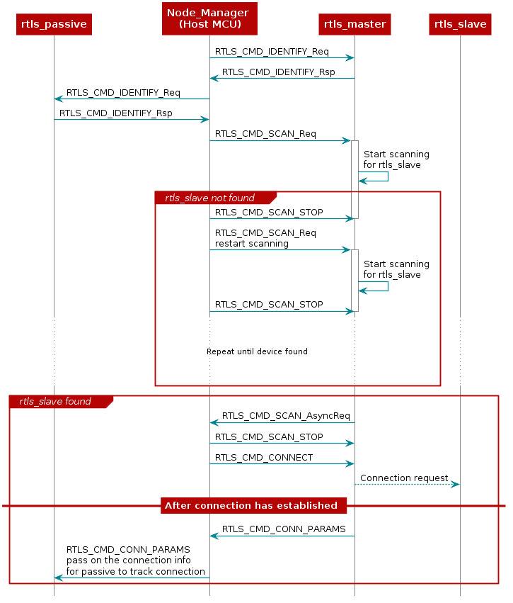
As covered in the BLE connections lab, before connecting, a scan must be
performed to see if the desired device is nearby. The scanning device will
inspect the advertising and optionally the scan response data to determine if
it wishes to connect to a given advertiser. Usually the scanner is looking
for a given token or string in the broadcast data of the advertiser. The RTLS
master will look for the string {'R','T','L','S','S','l','a','v','e'} starting
at the 3rd byte of the slave's advertisement data. If the advertising device
matches the filter, then it will be reported to the PC/Node Manager as
RTLS_CMD_SCAN responses, if not, it will be discarded.
If the Node Manager wishes to form a connection to one of the devices in the
scan results it can tell the rtls_master to do so by issuing an
RTLS_CMD_CONNECT along with the peer device's address and address type.
The address information can be extracted from the RTLS_CMD_SCAN responses
coming from the master node.
If the connection is successful, the RTLS_CMD_CONNECT response will be
received with status of RTLS_SUCCESS. The RTLS examples do not consider a
connection to be established between master and slave until the devices have
paired and formed an L2CAP Connection Oriented Channel (CoC). The L2CAP CoC
is used to send RTLS sync related information between master and slave.
This can include AoA parameters or ToF parameters, or a command to enable AoA
or ToF.
Immediately after the BLE connection is established
(i.e. GAP_LINK_ESTABLISHED_EVENT received from the stack), the rtls_master
will share the connection parameters with the PC/Node Manager via
RTLS_CMD_CONN_PARAMS. This information is needed by the connection monitor
inside rtls_passive in order to follow the connection between RTLS master
and slave.
Distributing Connection Parameters
The RTLSManager Python class will immediately relay any connection
parameters received (RTLS_CMD_CONN_PARAMS) to all of the passive nodes
connected. This does not need to be done manually.
Setting up RTLS Network in Python
Now that we understand the basics behind the RTLS network and how to set it up, let's write a bit of Python to automate this process using the template program we created above.
The commands required to setup a network belong to the RTLS UNPI subsystem and
can be found in the ss_rtls.py file.
We will use the rtls_example.py as a starting point. From the sections
above, we know that after the nodes are identified, we want to tell the master
to scan.
You can send a command to an RTLSNode instance by calling the builder class
associated with the command. For example, if you have an RTLSNode instance
called masterNode you can tell it to scan like so:
masterNode.rtls.scan()
After telling the node to scan, you will receive scan responses, the scan response packets are defined like this in Python:
struct = Struct(
    "eventType" / Int8ul,
    "addrType" / Enum(Int8ul),
    "addr" / NiceBytes(ReverseBytes(Byte[6])),
    "rssi" / Int8sl,
    "dataLen" / Int8ul,
    "data" / NiceBytes(Byte[this.dataLen])
)
In the last section, we covered that the rtls_master embedded node will
only report scan responses from devices that advertise as RTLS slave.
Therefore, there isn't much need to inspect the data payload unless desired.
Instead, it is adequate to store the addr and addrType fields from the
scan response as this is needed for the connect request. Assuming you have a
node message like the one from rtls_example.py(see top of while True loop)
then you can parse it like this:
if msg.command == 'RTLS_CMD_SCAN' and msg.type == 'AsyncReq':
    address = msg.payload.addr
    addressType = msg.payload.addrType
The code above will identify a scan result message then store the address and address type in a variable.
Asynchronous vs Synchronous commands in UNPI
You might have noticed that RTLS_CMD_SCAN is used to tell the node to start
scanning, receive status, and receive scan results.
This is possible within UNPI because each message can be one of the following
types
- Synchronous request
- Synchronous response
- Asynchronous request
In the case of RTLS_CMD_SCAN the message that initiates the scan on the
rtls_master is a synchronous request. The message that returns the status
of the scan start call is a synchronous response, and the message that
returns scan results is an asynchronous request. See the NPI chapter
in the TI BLE-Stack User's Guide
for more information.
Now, we have collected a list of scan results and are ready to connect.
First, we must wait until the rtls_master finishes scanning. When scanning
is complete, a message of type RTLS_CMD_SCAN_STOP will be sent to the PC
from the rtls_master node. By default, the code below will connect to the
first device that has {'R','T','L','S','S','l','a','v','e'} as part of the
advertising data.
If there may be multiple rtls_slave devices nearby. In this case, it is best
to specify your specific via address. If there is only one rtls_slave nearby
this step can be skipped.
If you don't know the address, you can read it from the UART
display of the slave device. Open a Serial terminal (like putty or teraterm)
on the user/UART port of the rtls_slave LaunchPad. Use 115200 baud, 8N1.
It should show the following text:
0x546C0E833F3D
Advertising
Based on this, you should set the following global variable (remove the 0x, and separate by :)
slaveAddr = '54:6C:0E:83:3F:3D' # Slave addr should be set here
Assuming again that we have a node message like the ones in rtls_example.py
the code for connecting is as below.
# Once the scan has stopped and we have a valid address, then
# connect
if msg.command == 'RTLS_CMD_SCAN_STOP':
    if address is not None and addressType is not None and (slaveAddr is None or slaveAddr == address):
        masterNode.rtls.connect(addressType, address)
    else:
        # If we didn't find the device, keep scanning.
        masterNode.rtls.scan()
Remember, the rtls_master will automatically send the connection parameters
once a BLE connection is formed with the rtls_slave. The RTLSManager python
class will intercept this and distribute it to all rtls_passive nodes so we
don't have to do this in our program. Upon receiving the connection parameters,
the connection monitor will begin following the connection between master and
slave. Note that it may take some time to establish a connection as this
does include LE Secure Connections pairing as well as opening an L2CAP
Connection Oriented Channel.
Equipped with the knowledge above, modify rtls_example.py to connect to
your slave device. The expected output is show here:
54:6C:0E:9F:12:27 TOF_MASTER, RTLS_MASTER
54:6C:0E:83:3A:A4 CM, TOF_PASSIVE, RTLS_PASSIVE

Sending example command RTLS_CMD_IDENTIFY; responses below

{"identifier": "54:6C:0E:9F:12:27", "message": {"originator": "Nwp", "type": "SyncRsp", "subsystem": "RTLS", "command": "RTLS_CMD_IDENTIFY", "payload": {"capabilities": {"CM": false, "AOA_TX": false, "AOA_RX": false, "TOF_SLAVE": false, "TOF_PASSIVE": false, "TOF_MASTER": true, "RTLS_SLAVE": false, "RTLS_MASTER": true, "RTLS_PASSIVE": false}, "identifier": "54:6C:0E:9F:12:27"}}}
{"identifier": "54:6C:0E:83:3A:A4", "message": {"originator": "Nwp", "type": "SyncRsp", "subsystem": "RTLS", "command": "RTLS_CMD_IDENTIFY", "payload": {"capabilities": {"CM": true, "AOA_TX": false, "AOA_RX": false, "TOF_SLAVE": false, "TOF_PASSIVE": true, "TOF_MASTER": false, "RTLS_SLAVE": false, "RTLS_MASTER": false, "RTLS_PASSIVE": true}, "identifier": "54:6C:0E:83:3A:A4"}}}
{"identifier": "54:6C:0E:9F:12:27", "message": {"originator": "Nwp", "type": "SyncRsp", "subsystem": "RTLS", "command": "RTLS_CMD_SCAN", "payload": {"status": "RTLS_SUCCESS"}}}
{"identifier": "54:6C:0E:9F:12:27", "message": {"originator": "Nwp", "type": "SyncRsp", "subsystem": "RTLS", "command": "RTLS_CMD_SCAN", "payload": {"status": "RTLS_SUCCESS"}}}
{"identifier": "54:6C:0E:9F:12:27", "message": {"originator": "Nwp", "type": "AsyncReq", "subsystem": "RTLS", "command": "RTLS_CMD_SCAN_STOP", "payload": {"status": "RTLS_SUCCESS"}}}
{"identifier": "54:6C:0E:9F:12:27", "message": {"originator": "Nwp", "type": "SyncRsp", "subsystem": "RTLS", "command": "RTLS_CMD_SCAN", "payload": {"status": "RTLS_SUCCESS"}}}
{"identifier": "54:6C:0E:9F:12:27", "message": {"originator": "Nwp", "type": "AsyncReq", "subsystem": "RTLS", "command": "RTLS_CMD_SCAN", "payload": {"eventType": 0, "addrType": 0, "addr": "54:6C:0E:83:3F:3D", "rssi": -31, "dataLen": 11, "data": "0A:09:52:54:4C:53:53:6C:61:76:65"}}}
{"identifier": "54:6C:0E:9F:12:27", "message": {"originator": "Nwp", "type": "AsyncReq", "subsystem": "RTLS", "command": "RTLS_CMD_SCAN_STOP", "payload": {"status": "RTLS_SUCCESS"}}}
{"identifier": "54:6C:0E:9F:12:27", "message": {"originator": "Nwp", "type": "SyncRsp", "subsystem": "RTLS", "command": "RTLS_CMD_CONNECT", "payload": {"status": "RTLS_SUCCESS"}}}
{"identifier": "54:6C:0E:9F:12:27", "message": {"originator": "Nwp", "type": "AsyncReq", "subsystem": "RTLS", "command": "RTLS_CMD_CONN_PARAMS", "payload": {"accessAddress": 3995831812, "connInterval": 160, "hopValue": 14, "mSCA": 0, "currChan": 14, "chanMap": [255, 255, 255, 255, 31]}}}
{"identifier": "54:6C:0E:83:3A:A4", "message": {"originator": "Nwp", "type": "SyncRsp", "subsystem": "RTLS", "command": "RTLS_CMD_CONN_PARAMS", "payload": {"status": "RTLS_SUCCESS"}}}
{"identifier": "54:6C:0E:83:3A:A4", "message": {"originator": "Nwp", "type": "AsyncReq", "subsystem": "RTLS", "command": "RTLS_CMD_CONNECT", "payload": {"status": "RTLS_SUCCESS"}}}
Connection established, all systems go!!!
{"identifier": "54:6C:0E:9F:12:27", "message": {"originator": "Nwp", "type": "AsyncReq", "subsystem": "RTLS", "command": "RTLS_CMD_CONNECT", "payload": {"status": "RTLS_SUCCESS"}}}
Connection established, all systems go!!!
Solution is below.
import queue
import time
import logging
import sys

from rtls.rtlsmanager import RTLSManager
from rtls.rtlsnode import RTLSNode, Subscriber


# Uncomment the below to get raw serial transaction logs

# logging.basicConfig(stream=sys.stdout, level=logging.DEBUG,
#                     format='[%(asctime)s] {%(filename)s:%(lineno)d} %(levelname)s - %(message)s')


if __name__ == '__main__':
    # Initialize, but don't start RTLS Nodes to give to the RTLSManager
    my_nodes = [RTLSNode('COM14', 115200), RTLSNode('COM47', 115200)]

    # Initialize references to the connected devices
    masterNode = None
    address = None
    addressType = None
    passiveNodes = []
    # If slave addr is None, the script will connect to the first RTLS slave
    # that it found. If you wish to connect to a specific device
    # (in the case of multiple RTLS slaves) then you may specify the address
    # explicitly as given in the comment to the right
    slaveAddr = None #'54:6C:0E:83:3F:3D'

    # Initialize manager reference, because on Exception we need to stop the manager to stop all the threads.
    manager = None
    try:
        # Start an RTLSManager instance without WebSocket server enabled
        manager = RTLSManager(my_nodes, wssport=None)
        # Create a subscriber object for RTLSManager messages
        managerSub = Subscriber(queue=queue.PriorityQueue(), interest=None, transient=False, eventloop=None)
        # Attach subscriber to manager
        manager.add_subscriber(managerSub)

        # Tell the manager to automatically distribute connection parameters
        manager.auto_params = True

        # Start RTLS Node threads, Serial threads, and manager thread
        manager.start()

        # Wait until nodes have responded to automatic identify command, and assign nodes to application references
        timeout = time.time() + 5
        while time.time() < timeout:
            if all([node.identifier is not None for node in manager.nodes]):
                try:
                    masterNode = next((n for n in manager.nodes if n.capabilities.get('RTLS_MASTER', False)))
                except StopIteration:
                    pass
                passiveNodes = [n for n in manager.nodes if not n.capabilities.get('RTLS_MASTER', False)]
                break
            time.sleep(0.1)

        # Exit if no master node exists
        if not masterNode:
            raise RuntimeError("No RTLS Master node connected")

        #
        # At this point the connected devices are initialized and ready
        #

        # Display list of connected devices
        print(f"{masterNode.identifier} {', '.join([str(c) for c, e in masterNode.capabilities.items() if e])}")
        for pn in passiveNodes:
            print(f"{pn.identifier} {', '.join([str(c) for c, e in pn.capabilities.items() if e])}")

        print("\nSending example command RTLS_CMD_IDENTIFY; responses below\n")

        # Send an example command to each of them, from commands listed at the bottom of rtls/ss_rtls.py
        for n in passiveNodes + [masterNode]:
            n.rtls.identify()

        while True:
            # Get messages from manager
            try:
                node_msg = managerSub.pend(block=True, timeout=0.05)
                from_node = node_msg.identifier
                msg = node_msg.message.item
                print(node_msg.as_json())

                # After identify is received, we start scanning
                if msg.command == 'RTLS_CMD_IDENTIFY':
                      masterNode.rtls.scan()

                # Once we start scaning, we will save the address of the
                # last scan response
                if msg.command == 'RTLS_CMD_SCAN' and msg.type == 'AsyncReq':
                    address = msg.payload.addr
                    addressType = msg.payload.addrType

                # Once the scan has stopped and we have a valid address, then
                # connect
                if msg.command == 'RTLS_CMD_SCAN_STOP':
                    if address is not None and addressType is not None and (slaveAddr is None or slaveAddr == address):
                        masterNode.rtls.connect(addressType, address)
                    else:
                        # If we didn't find the device, keep scanning.
                        masterNode.rtls.scan()


                # Once we are connected, then we can do stuff
                if msg.command == 'RTLS_CMD_CONNECT' and msg.type == 'AsyncReq' and msg.payload.status == 'RTLS_SUCCESS':
                    print ("Connection established, all systems go!!!")

            except queue.Empty:
                pass

    finally:
        if manager:
            manager.stop()
You made it to the end
Excellent work!
This work is licensed under a Creative Commons Attribution-NonCommercial-NoDerivatives 4.0 International License.