Frequency-Hopping Mode
Introduction
Applications that are developed using TI 15.4-Stack can be configured to operate the network in frequency-hopping configuration where the network devices hop on different frequencies. TI 15.4-Stack supports an unslotted channel-hopping feature based on the directed frame exchange (DFE) mode of the Wi-SUN FAN specification v1.0.
Attention
Frequency hopping is only supported on Sub-1 GHz frequency bands.
Two types of end devices are supported:
- Sleepy End Device: These devices do not change channels by themselves but follow that of the collector. All communication to these devices should be made using short addressing.
- Non-Sleepy End Device: These devices can either hop on multiple channels based on direct hash channel function (DH1CF) or operate on a fixed channel based on the channel function configuration. All communication to these devices should be made using extended address mode.
The Collector device can either hop on multiple channels based on direct hash channel function DH1CF or operate on a fixed channel based on the channel function configuration.
DH1CF generates a pseudo-random sequence of channels on which to hop based on the extended address of the node; thus, the pseudo-random sequence of channels is unique to each node. Each node supports two types of channel-hopping sequences:
- Unicast
- Broadcast
Frequency hopping for each node is based on the unicast channel hopping sequence of those nodes (see Figure 30.).
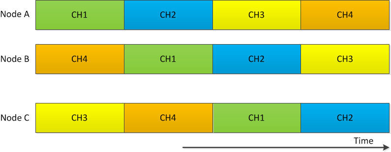
Figure 30. Unicast Hopping Sequence
To enable broadcast transmissions, the coordinator starts a broadcast schedule (see Figure 31.). Every other device follows the broadcast-hopping sequence received from the PAN coordinator. A device performs unicast hopping until the next broadcast dwell time. Then, the device switches to the broadcast- hopping channel for the broadcast dwell time and resumes unicast hopping at the end of the broadcast dwell interval.
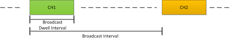
Figure 31. Broadcast Channel Hopping Sequence
The application can specify the broadcast dwell interval (default is 250 ms),
channel hopping function (default is Fixed Channel), and the list of channels
to hop (based on PHY Descriptor ID; for example, the default value of 1
represents 129 channels). Additionally, the broadcast interval (default is 4250
ms) can be specified on the PAN coordinator. When the hopping function is set
to Fixed, the node must stay on the channel set by
ApiMac_FHAttribute_unicastFixedChannel or
ApiMac_FHAttribute_broadcastFixedChannel during the unicast and broadcast
dwell times, respectively.
Note
The broadcast dwell time can be set to 0 to disable broadcast transmission. This can be especially helpful in saving power on sleepy end devices when broadcast transmission are not used in application as the device would no longer be required to power up during broadcast slots.
Note
A set of channels can also be excluded from the hopping channels by using
the ApiMac_FHAttribute_unicastExcludedChannels and
ApiMac_FHAttribute_broadcastExcludedChannels PIBs as defined in
Stack Configuration Knobs.
A special type of transmission called async transmission is also supported. In frequency-hopping mode, a device transmits any one of the Async frame types (as defined in the Wi-SUN FAN specification) in all of the requested channels (see Wi-SUN FAN Specification). This enables a hopping device to receive such a frame irrespective of the hopping sequence. Thus, the async transmission can be used to exchange channel-hopping information. This feature is especially useful in initial network formation as explained in Network Join.
When channel-hopping information of a neighbor is received, TI 15.4-Stack
tracks the hopping sequences of the neighbor hopping devices and enables
successful unicast and broadcast transmissions; thus, hiding the complexities
of maintaining synchronization from the application and easing the task of
developing applications with frequency hopping feature. To support short
address mode the FH_COORD_SHORT_ADDRESS should be configured on end device
to match the short address of the collector used.
Network Operations
In frequency hopping mode, nodes operate as one of the following device types:
- PAN coordinator
- Non-sleepy device
- Sleepy device
A typical star topology has a single PAN coordinator connected to a set of non-sleepy or sleepy devices. Each network is identified by a specific network name, which is an ASCII value of 32 bytes and a 16-bit PAN Identifier. The network name (NetName) is a unique network identifier that is configured by the application using frequency hopping and PAN information base (FH-PIB) attributes. Maintenance of the NetName is beyond the scope of TI 15.4-Stack and is not used to filter frames.
The sections below explain various network operations important to understand when developing a frequency hopping-enabled network over TI 15.4-Stack.
Network Start-Up
Figure 32. shows how a frequency-hopping network is started by starting the PAN coordinator in frequency-hopping mode.
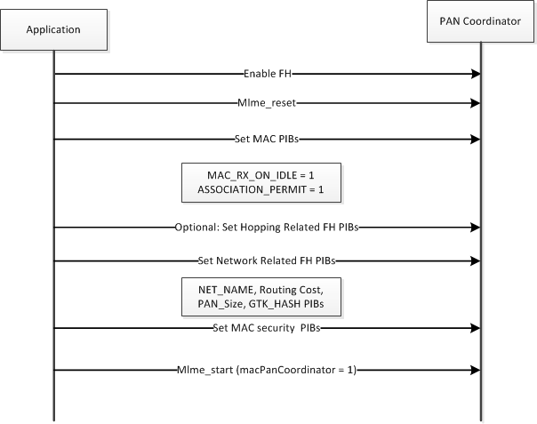
Figure 32. Start-Up Sequence of PAN Coordinator
The PIB attributes that are related to frequency-hopping configuration are explained in Stack Configuration Knobs. The NetName is a 32-bit ASCII value to be set by the application. The routing cost must be set to zero.
Initially, the PAN size must be set to zero; later, the PAN size must be updated based upon the number of nodes joined.
Note
This NetName value is not used by the TI 15.4-Stack to make any decision; instead, the value is carried in a PAN Advertisement frame that can be parsed by a receiving application. Similarly, the GTK HASH 0, GTK HASH 1, GTK HASH2, and GTK HASH 3 can be used to determine the validity of GMK keys that are in use and are beyond the scope of TI 15.4-Stack.
Finally, start MAC using the macStart API, which specifies that the node is a coordinator.
Device Start-Up
Figure 33. shows the start-up sequence of the device.
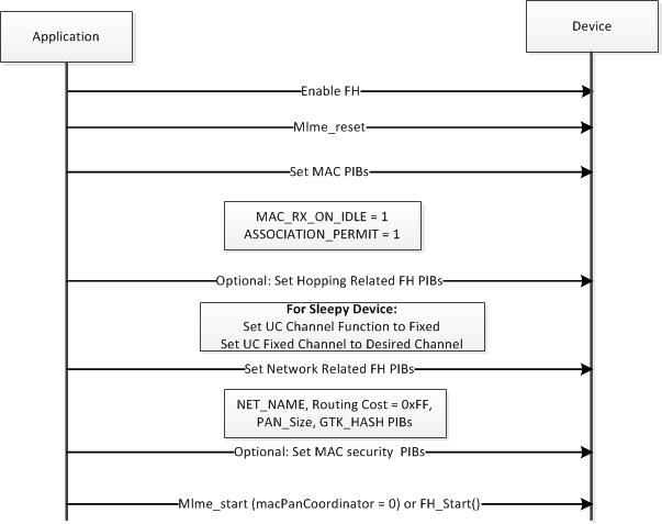
Figure 33. Start-Up Sequence of the Device
Wi-SUN FAN v1.0 does not specify sleep mode operation, but the TI 15.4-Stack implements a proprietary extension over the behavior defined in the Wi-SUN FAN and IEEE 802.15.4 MAC protocols (see Sleep Mode Operation) to enable sleepy devices in the frequency-hopping networks based on TI 15.4-Stack. The channel-hopping function for a sleepy device must be set to Fixed, and the fixed channel can be set to any desired channel. The security keys can be set at start-up (if the security keys are already pre-configured for the network), or the security keys can be set after obtaining the same through a key exchange. The key exchange protocol must be handled above the MAC layer.
The routing cost must be set to a high value (0xFFFF) to indicate that the device has not joined the network; later, it can be updated by the application based on the routing metric used.
Note
The sequence to start the sleepy and non-sleepy devices is the same until they join a network. A sleepy device is configured to be sleepy by setting the MAC PIB (macRxOnWhenIdle) to zero only after it joins the network (see Network Join). In other words, the sleep mode operation uses low-power mode only for data exchange after successfully joining the network.
Network Join
To join to a network, a node must go through the two phases described as follows.
Phase 1: Exchange of Channel-Hopping Sequence Information Through Asynchronous Messages
Asynchronous messages are sent back-to-back over a specified channel list. This action enables a receiver to receive such frames with high probability, irrespective of the hopping sequence. Four different asynchronous messages are supported by TI 15.4-Stack as defined in the Wi-SUN FAN specification. All asynchronous frames are transmitted based on a trickle timer [RFC 6206]. The Imin, Imax, and K for the trickle algorithm are recommended to be set at 1 min, 16 min, and 1, respectively.
Brief descriptions of the four types of asynchronous messages follow:
- PAN Advertisement Solicit (PAS):
- PAS messages are used by a device to request a coordinator or other joined nodes to transmit a PAN Advertisement frame.
- Upon reception of the PAN Advertisement frame, a joining application can detect the NetName IE in the frame and then use the name to determine whether or not to reset PA trickle timer.
- PAN Advertisement (PA):
- PA frames can be transmitted by a coordinator or by a joined node to inform neighbors about the PAN size, Routing cost, and PAN ID.
- The trickle timer associated with PA transmissions is programmed to be reset on reception of a PAS frame.
- Upon, reception of the PAS frame, nodes communicate with the transmitter of the PA frames (note the hopping sequence is carried in the PA frame).
- The device can choose one of the source nodes of the PA frame as relay to perform an Authentication and Secure Key Exchange protocol that must be implemented by the application running over the TI 15.4-Stack. Example applications (collector and sensor) included in TI 15.4- Stack do not demonstrate this feature.
- PAN Configuration Solicit (PCS):
- When a device has the group master key (GMK) keys used in the network, the device can request the transmission of a PAN Configuration frame.
- PCS messages are transmitted by a node to request neighbors or the coordinator transmit a PAN Config frame.
- PAN Configuration (PC):
- PC messages are transmitted by the coordinator or a joined node based on a trickle timer that must be reset upon reception of a PCS frame.
- PC frames carry the broadcast-hopping sequence and the hash values of the list of GMK keys that are actively used.
- Upon reception of a PC frame, a device detects that the channel-hopping exchanges are completed.
When using the frequency-hopping configuration on star-network topology, TI recommends the following:
- The PAN coordinator transmits PA and PC frames based on separate trickle timers. TI recommends that developers refer to the collector example application implementation located under the examples folder in the TI 15.4-Stack installation directory).
- Devices transmit PAS and PCS frames for the purpose of joining; then, the devices suspend the trickle timer after a successful join. TI recommends that developers refer to the sensor example application as a reference on how to implement this action, or that they use the implementation in the sensor example application as-is as a starting point for custom applications.
- Devices must also implement the suppression mechanism to limit the number of PAS and PCS frames transmitted. TI recommends developers refer to the sensor example application (examples folder in the TI 15.4-Stack installation directory) as a reference for implementing this action, or use the implementation in the sensor example application as-is as a starting point for custom applications.
Phase 2: Proprietary Association Procedure to Inform Coordinator of the Network Join (This is an Optional Step)
Because the frequency hopping join procedure (defined by the Wi-SUN specification) is silent, the PAN coordinator cannot detect if the device has successfully joined the network. The TI 15.4-Stack example applications use an additional step for network join. The MAC layer association procedure described in the IEEE 802.15.4 specification is used after the PCS indicates to the PAN coordinator that the device has successfully joined the frequency-hopping network.
In addition to informing the coordinator that the device has successfully joined the network, the optional mechanism allows the PAN coordinator to detect if the joining node is sleepy or always-on through the capability information field of the association request message sent by the device to the PAN coordinator. This optional mechanism is required for the PAN coordinator application to determine the following:
- If the application must buffer the message until the device polls for some configured amount of time in case the message is for a sleepy device
- If the application must send the message OTA as soon as the message- transmit request is generated
Although this step is not required for data exchange (because EUI addresses are used instead of short addresses for communication in frequency-hopping mode), TI recommends using this optional procedure in the applications using the frequency-hopping configuration of the TI 15.4-Stack to enable the coordinator application to build the list of joined nodes and to detect if the newly joined device is sleepy or is an always-on device.
Note
The association procedure must be started at least 2 seconds after
reception of a PAN configuration frame. Upon failure, the association
procedure can be independently retried up to the retry limit of the
application. For a sleepy device, the ApiMac_attribute_RxOnWhenIdle
should be set to zero only after a successful completion of the mac-
association procedure.
Figure 34. and Figure 35. shows the procedure for sleepy and non-sleepy devices, respectively.

Figure 34. Joining Procedure for a Sleepy Frequency-Hopping Device
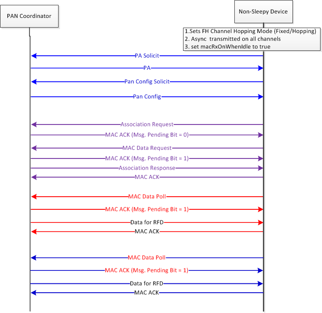
Figure 35. Joining Procedure for a Nonsleepy Frequency-Hopping Device
Data Exchange
Three types of data-exchange mechanisms are supported by the TI 15.4-Stack:
- Unicast data exchange
- Broadcast data exchange
- Asynchronous frame exchange
Destination address mode should be based on end-device being sleepy or non-
sleepy. To initiate a unicast or broadcast frame exchange, the API
ApiMac_mcpsDataReq should be used. To transmit an asynchronous frame,
ApiMac_mlmeWSAsyncReq should be used. The determination of whether the
message is unicast or broadcast is done based on the destination address mode
used in the data request parameter type ApiMac_mcpsDataReq_t (see
Table 7.).
| Message Type | Source Address Mode | Destination Address Mode | Destination Address |
|---|---|---|---|
| Unicast (sleepy device) | 2 | 2 | Specified by the application |
| Unicast (non-sleepy device) | 3 | 3 | Specified by the application |
| Broadcast | 3/2 | 0 | Ignored by stack |
Unicast Data Exchange
Unicast data exchange in frequency-hopping mode occurs on the channel of the destination node. A node transmits the frame on the expected receive channel of the destination node. The entire frame exchange occurs on the same channel (see Figure 36.). Subsequent data exchange occurs on the channel on which the receiver is hopping at the time of transmission; this subsequent data exchange is independent from earlier transmissions.
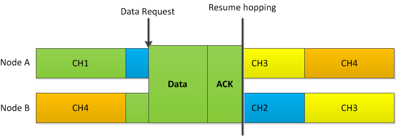
Figure 36. Data Exchange With TI 15.4-Stack in Frequency-Hopping Configuration
To transmit a unicast frame to a neighbor, the hopping information was received by the node in some earlier frame. The hopping information could have been received through the reception of any type of asynchronous frames from the destination node. Hence, an application should ensure that such a frame is received from destination node before initiating a data request.
If a data request is issued to a node whose entry is not in the neighbor table,
the error code ApiMac_status_fhNotInNeighborTable (0x64) specifies that the
node that is not in the neighbor table is returned to the application by TI
15.4-Stack. Also, an expiry is associated with each neighbor table entry. The
default time of the expiry is 2 hours for hopping neighbors. The 2 hour default
expiry is set because the hopping information stored in the neighbor table may
not be useful beyond that time limit for a successful data exchange (due to loss
in synchronization caused by inherent clock drifts). Any data exchange helps the
node to resynchronize the entry; thus, the entry is considered active for the
next 2 hours. If a data request is sent for an expired neighbor, the message is
not sent to the destination and a status of ApiMac_status_fhExpiredNode
(0x6C) is returned to the application. Unicast frames are only transmitted in
unicast slots.
Note
The lifetime of a hopping neighbor can be changed to any other desired value
in the range of 5 minutes to 600 minutes (10 hours) by using the PIB
attribute, ApiMac_FHAttribute_neighborValidTime, which is specified in
minutes.
Broadcast Frame Exchange
Broadcast frames are transmitted only during the broadcast dwell interval as
shown in Figure 31.. This can lead to situations where
frames are out of order between a unicast and broadcast frame (that is, the
order in which frames are requested to be transmitted by the application could
be different from the order in which they are transmitted over the air). Thus,
the order in which the ApiMac_mcpsDataReq confirm is received may be
different from the order in which ApiMac_mcpsDataReq is sent. The msdu-
handle should be used to match the request primitive to the corresponding
confirm primitive by the application.
An application on the PAN coordinator can transmit a broadcast frame any time
because the PAN coordinator starts the broadcast hopping as soon as the
application is started. All other nodes should wait for the reception of a PAN
Configuration frame from the PAN coordinator to start the broadcast-hopping
sequence. An application on these other nodes should wait for the reception of
the PAN Configuration frames; then the application can set the source address of
the PAN Configuration frame (if it selects to use that node as a Parent) to the
FH_MAC_TRACK_PARENT PIB before issuing a request of broadcast frame
exchange. If an application issues a broadcast data request while the node has
not yet started following a broadcast hopping sequence, the stack returns an
ApiMac_status_badState (0x19) error code.
Asynchronous Frame Exchange
Asynchronous frames are transmitted by a device on the list of channels specified by user in the Async request. Figure 37. shows that the device deviates from the hopping sequence and performs this operation.
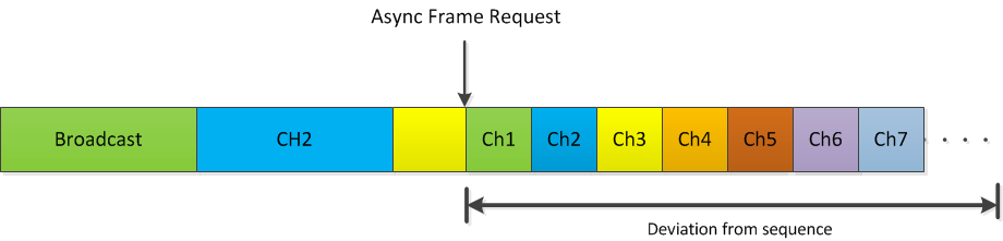
Figure 37. Asynchronous Frame Exchange
The objective of asynchronous frame exchange is to transmit data on all available channels (default = 129); thus, asynchronous frame exchange can take a few seconds to complete (worst case is approximately 4 seconds). Such transmissions are typically controlled by trickle timers and are not recommended to be transmitted frequently (refer to References). Optionally, a device may issue an Async Request with a Stop command, which will stop an ongoing Async frame exchange.
Sleep Mode Operation
Wi-SUN FAN v1.0 does not define a sleep mode operation. However, TI 15.4-Stack supports a proprietary sleep mode operation using a mechanism similar to TI 15.4Stack non-beacon configuration operation, which uses indirect transmissions. In sleep mode operation the address mode should be set to short address mode.
The sleep mode operation is explained in Figure 38.. Because the joining procedure is explained in Network Join, the data exchange mechanism is emphasized in this section.
After reception of PAN Config frame, the macRxOnWhenIdle should be set to zero to enable sleep mode operation. The sleepy device transmits frames to the PAN coordinator based on the hopping sequence. TI 15.4-Stack on the sleepy device operates on a fixed channel and will not hop independently.
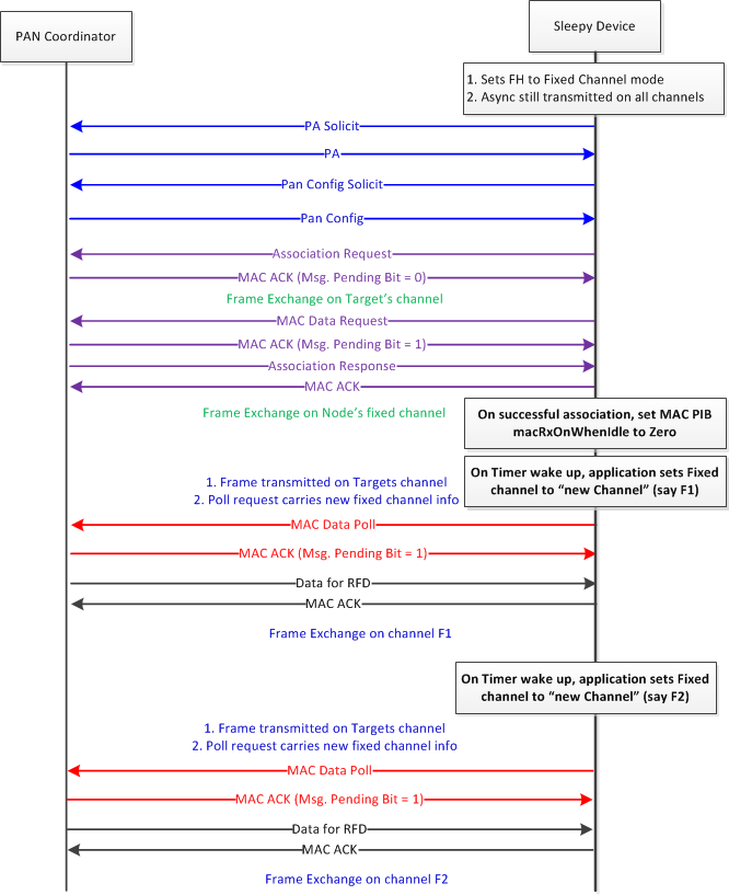
Figure 38. Sleep Mode Operation in Frequency-Hopping Mode
Maintaining a Connection for End Nodes
In a typical star network, the devices have to keep track of unicast and broadcast timing of Coordinator’s hopping sequences while the coordinator has to do for the unicast timing information of all the connected devices.
The timing information of the unicast and broadcast sequence of a device is carried in unicast timing and frame type information element (UTT-IE) and broadcast timing Information element (BT-IE), respectively. All data frames with destination address mode set to extended or None shall carry UTT-IE and BT-IE. The ACK frames from PAN-Coordinator will contain both the UTT-IE and BT-IE irrespective of address mode, while those from other non-sleepy end devices will carry UTT-IE alone. The timing information corresponding to the source of the received Data/ACK frame is updated based on received frames.
The lifetime of a neighbor table is based on the last time the entry was
updated. As long as a frame is received from a neighbor once every neighbor
valid time, it is kept active. The neighbor valid time for a hopping neighbor
is set to 2 hours by default. Neighbor valid time can be changed using the
MAC_FHPIB_NEIGHBOR_VALID_TIME PIB attribute. After that period the entry is
considered as expired. Any neighbor table entry is deleted if it is not updated
within the last 10 hours.
The period within which at least one data frame should be exchanged to maintain reliable communication depends on the dwell time value used by the PAN coordinator. TI recommends keeping this period for at most 10 minutes or 25 minutes, for a PAN coordinator dwell time of 100 ms and 250 ms respectively.
Disassociating
The frequency-hopping mode also supports the disassociation command defined in IEEE 802.15.4, similar to the nonfrequency-hopping mode.
Stack Configuration Knobs
The frequency-hopping mode features can be controlled through a set of MAC FHPIB attributes. Some of these PIBs affect TI 15.4-Stack operation directly, while others are provided to help applications generate the required Asynchronous frames. This section explains the MAC FHPIB attributes.
Parameters Controlling the Unicast Channel-Hopping Sequence of the Node
The parameters controlling the unicast hopping must be set after the FH is enabled and before the MAC or FH-start API is called (see Table 8.). These values must not be changed after the node starts the hopping sequence. To change these values the nodes have to be power cycled or reset.
| PIB | PIB ID | Range | Default | Description |
|---|---|---|---|---|
| ApiMac_FHAttribute_unicastDwellInterval | 0x2004 | 15 to 250 (ms) | 250 | Amount of time spent on each channel |
| ApiMac_FHAttribute_unicastChannelFunction | 0x2008 | 0 or 2 | 0 | Whether to hop or not. Only two values are supported: 0 – Fixed 2 – DH1CF-based hopping |
| ApiMac_FHAttribute_unicastFixedChannel | 0x200C | 0 – maximum channel based on PHY configuration | 0 | The channel to use during unicast hopping when the channel function is fixed |
| ApiMac_FHAttribute_unicastExcludedChannels | 0x2002 | 17 bytes | All zeros | The list of channels to avoid when channel function is 2. Each bit represents a channel, starting from the LSB of the first byte which, represents Channel 0 |
Parameters Controlling the Broadcast Channel-Hopping Sequence
These parameters must only be set on the PAN coordinator (see Table 9.). The parameters must be set after the FH is enabled and before the MAC or FH-start API is called. Other devices obtain this information on reception of a PC (an Asynchronous message) message from the PAN- Coordinator. Devices then perform their broadcast hopping based on the received configuration. The received configuration can be read from these PIBs after the reception of a PAN Config frame from the parent of a node.
| PIB | PIB Id | Range | Default | Description |
|---|---|---|---|---|
| ApiMac_FHAttribute_broadcastInterval | 0x2001 | 15 to 16777215 ms | 4250 | The interval between two different broadcast dwell interval |
| ApiMac_FHAttribute_broadcastDwellInterval | 0x2005 | 0 to 250 ms | 250 | Amount of time spent during broadcast dwell interval. Setting this value to 0 will disable broadcast transmissions. |
| ApiMac_FHAttribute_broadcastChannelFunction | 0x2009 | 0 or 2 | 0 | Whether to hop or not. Only two values are supported: 0 – Fixed 2 – DH1CF based hopping |
| ApiMac_FHAttribute_broadcastFixedChannel | 0x200D | 0 – maximum channel based on PHY configuration | 0 | The channel to use during broadcast dwell interval when the channel function is fixed |
| ApiMac_FHAttribute_broadcastExcludedChannels | 0x2003 | 17 bytes | All zeros | The list of channels to avoid when the channel function is 2. Each bit represents a channel, starting from the LSB of the first byte, which represents Channel 0. |
Note
A large value of broadcast interval implies a higher delay in transmitting broadcast frames. An application could decide to increase or decrease this interval based on the perceived requirement for handling broadcast frames.
On the device side, an application must set the source address of the chosen parent to the MAC TRACK PARENT PIB (see Table 10.). FH stack follows the broadcast hopping sequence of the chosen parent. An application can choose a parent based on the received source address of the PAN configuration frames. However, performance loss may occur due to loss in broadcast synchronization, which is corrected based on the subsequent PAN Configuration frame received from the new parent.
| PIB | PIB Id | Range | Default | Description |
|---|---|---|---|---|
| ApiMac_FHAttribute_trackParentEUI | 0x2000 | Any | 0xFFFFFFFF | Source address of the parent. |
Changing Broadcast Sequence Values in the Middle of Network Operation
A PAN coordinator may choose to modify the broadcast interval during a network operation. To do so the application of the PAN coordinator must set the values as required, and then increment the value of the MAC_FHPIB_BROCAST_SCHED_ID PIB (see Table 11.).
| PIB | PIB Id | Range | Default | Description |
|---|---|---|---|---|
| ApiMac_FHAttribute_broadcastSchedId | 0x200B | 0 to 65535 | 0 | A value representing a given broadcast configuration. It must be incremented when broadcast configurations are changed. |
Transmit PAN Config frames more frequently to enable the dissemination of this information to the network.
Note
The performance of the network may be affected during this change in configuration time as it requires some time for the nodes to update their hopping sequences.
Parameters to Control Frequency of the Operation of Hopping Mode
The following parameters can be set to control specific functions, as defined in Table 12..
| PIB | PIB Id | Range | Default | Description |
|---|---|---|---|---|
| ApiMac_FHAttribute_clockDrift | 0x2006 | 0 to 255 | 20 | Represents the accuracy of the system clock in ppm. A value of 255 implies that the information is not provided. |
| ApiMac_FHAttribute_timingAccuracy | 0x2007 | 0 to 255 | 0 | Accuracy of provided timing information in 10s of micro seconds. |
| ApiMac_FHAttribute_neighborValidTime | 0x2019 | 5 to 600 (minutes) | 120 | The time in minutes for which a hopping neighbor is considered valid after reception of a Data/ACK from it. |
TI recommends not changing the values listed in Table 12., and using the default values.
Parameters to Control Neighbor Table Size
The amount of heap memory occupied by the FH neighbor table can be controlled through FH PIB attributes. The total number of end devices supported must be less than 50. If a deployment only requires a lesser number of devices, a lower number of neighbor table entries can be specified, thereby allowing more heap for the application. When configuring the number of neighbor table entries, both non-sleepy and sleepy devices must be changed together with MAC_FHPIB_NUM_NON_SLEEPY_DEVICES set first.
| PIB | PIB Id | Range | Default | Description |
|---|---|---|---|---|
| MAC_FHPIB_NUM_NON_SLEEPY_DEVICES | 0x201b | 0 to 50 | 2 | Total number of non-sleepy neighbors supported. |
| MAC_FHPIB_NUM_SLEEPY_DEVICES | 0x201c | 0 to 50 | 48 | Total number of sleepy neighbors supported. |
Note
The number of non-sleepy and sleepy neighbors can only be configured before issuing a network start or FHAPI_start API. The total number of end devices supported must be less than 50. When configuring the number of neighbor table entries, both non-sleepy and sleepy devices must be changed together with MAC_FHPIB_NUM_NON_SLEEPY_DEVICES set first.
| PIB | PIB Id | Range | Default | Description |
|---|---|---|---|---|
| MAC_FHPIB_BASE_BACKOFF | 0x201a | 0 to 16 | 8 | Additional back off parameter on target channel to account for interference (ms). |
| MAC_FHPIB_NEIGHBOR_VALID_TIME | 0x2019 | 0 to 65535 (minutes) | 120 | The time in minutes for which a hopping neighbor is considered valid after reception of a Data/ACK from it. |
The MAC_FHPIB_BASE_BACKOFF enables FH devices to mitigate interference, which causes a higher delay for packet transmission when interference is observed. The interference mitigation feature can be disabled by setting this parameter to zero (although it is not recommended to do so). TI recommends not changing these values and using the default values.
Parameters to Enable Application Generate and Process Asynchronous Frames
The following PIB attributes represent different fields of the Asynchronous frames (see Table 15.). The attributes are used to generate the required IEs when an async request is made by application based on the async frame type. The TI 15.4-Stack is responsible for only using these PIBs to encode the async frames and does not use these values to make any decisions on its operation. It is up to the application to use these fields if needed to perform any relevant operation.
| PIB | PIB Id | Range | Default | Description |
|---|---|---|---|---|
| ApiMac_FHAttribute_panSize | 0x200E | 0 to 65535 | 0 | The size of PAN network |
| ApiMac_FHAttribute_routingCost | 0x200F | 0 to 255 | 0 | Zero for PAN Coordinator and Non- Zero for other devices. Actual metric used is beyond the scope of MAC. This can be used to choose a parent. |
| ApiMac_FHAttribute_routingMethod | 0x2010 | 0 or 1 | 1 | Specify the type of routing protocol used. Typical values are 0 – MHDS, 1 – RPL |
| ApiMac_FHAttribute_eapolReady | 0x2011 | 0 or 1 | 1 | Specify whether the node can support EAPOL to perform authentication and key exchange |
| ApiMac_FHAttribute_fanTPSVersion | 0x2012 | 0 to 255 | 1 | Wi-SUN FAN version number |
| ApiMac_FHAttribute_netName | 0x2013 | 32 bytes | All zeros | Null terminated string |
| ApiMac_FHAttribute_panVersion | 0x2014 | 0 to 65535 | 00000 | Must be incremented whenever a configuration changes such as broadcast information or GTK Hash values are changed. |
| ApiMac_FHAttribute_gtk0Hash | 0x2015 | 8 bytes | All zeros | The Hash value that can be used by the application to decide the validity of an exchanged GMK key with ID 0. |
| ApiMac_FHAttribute_gtk1Hash | 0x2016 | 8 bytes | All zeros | The Hash value that can be used by the application to decide the validity of an exchanged GMK key with ID 1. |
| ApiMac_FHAttribute_gtk2Hash | 0x2017 | 8 bytes | All zeros | The Hash value that can be used by the application to decide the validity of an exchanged GMK key with ID 2. |
| ApiMac_FHAttribute_gtk3Hash | 0x2018 | 8 bytes | All zeros | The Hash value that can be used by the application to decide the validity of an exchanged GMK key with ID 3. |