Network Processor Interface (NPI)
TI’s Network Processor Interface (NPI) is used for establishing a serial data link between a TI SoC and external MCUs or PCs. It is an abstraction layer above the serial interface (UART or SPI) that handles sending / receiving data power management, and data parsing It is mainly used by TI’s network processor solutions. There are two types of NPI used by BLE and they are described in the following sections.
Legacy NPI
Anything that is not specifically “Unified NPI” is Legacy NPI. For example, the hostTest project uses Legacy NPI. For the remainder of this section, NPI will always refer to Legacy NPI
TI provides the source code for NPI and it can be found in the following files at $SDK_INSTALL$sourcetiblestacknpisrc:
- npi_client_mt.c
- npi_frame_hci.c
- npi_fram_mt.c
- npi_rxbuf.c
- npi_task.c
- npi_tl.c
- npi_tl_spi.c or npi_tl_uart.c
Signaling Protocol
Each processor in an NPI solution must occupy either the master or slave role. The TI wireless SoC generally occupies the slave role in the network processor examples included in the SDK.
NPI Signaling
In order to properly manage the power domains of the device, there must be a way for an external host to wake the network processor from low power modes. This is done through the inclusion of the following pins:
- Master Ready (MRDY): A GPIO pin whose logic level indicates the state of the master processor. MRDY is an active low (low true) signal. An MRDY event indicates that the master processor is ready to send or receive data.
- Slave Ready (SRDY): A GPIO pin whose logic level indicates the state of the slave processor. SRDY is an active low (low true) signal. An SRDY event indicates that the slave processor is ready to send or receive data.
In the slave role, MRDY is an input pin and SRDY is an output in. In the master role, MRDY is an output pin and SRDY is an input pin.
NPI Handshake
In order to start an NPI transaction, there first must occur a handshake sequence using the MRDY and SRDY pins. This handshake is required in order to guarantee that both devices are awake and ready to send and/or receive data. Whichever device first starts the handshake sequence is termed the “initiator”. Either the slave or the master may may be the imitator. The NPI transaction is completed by the master raising MRDY followed by the slave raising SRDY.
The figures below illustrate both master and slave-initiated NPI transactions
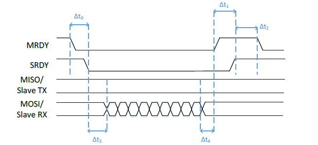
Figure 84. Timing for Master-Initiated NPI Transaction

Figure 85. Timing for Slave-Initiated NPI Transaction
Packet Format
The NPI module handles the serial driver-level packet formatting, stripping of the NPI, header and FCS when unpacking. This section will describe the packet format to be used with NPI.
Note
This section does not consider the packet format of the data payload section of the NPI packet format as this is dependent on the NPI use case (i.e. HCI packet format for BLE).
The packet format is dependent on the serial protocol being used and described in the following sections.
SPI
In order to understand the structure of the TL packet format, it is necessary to understand the complications inherent in the SPI protocol. The first limitation is that the SPI master must trigger the clock signal (SCLK) in order to receive bytes from the slave. If the slave is sending a message, then the master must know how long this message is in order to receive the complete message. The other limitation of SPI is that if the clock signal is triggered, the master or slave must transmit empty bytes if they have nothing to send. The simple scenario when this occurs is during either a communication sequence where either the master or slave receives only empty bytes. These messages of strictly empty bytes could be easily ignored but the bidirectional message scenario requires more complex handling. If the slave and master are both transmitting non-empty bytes then the shorter message will have to be padded with empty bytes so that the longer message can be fully transmitted. Determining which bytes of message bytes versus empty bytes in this scenario requires message delimitation. In order to handle these limitations of SPI, the NPI SPI Frame is used for all NPI messages sent over SPI.
The NPI SPI Frame has four fields described thus and pictured below:
- 1 byte Start of Frame (SOF): always 0xFE
- 1 byte length: length of the data payload field (must be between 0-255 bytes)
- 0-255 byte Data Payload
- 1 byte Frame Check Sequence (FCS): calculated by doing a XOR on each byte of the frame in the order they are sent/received on the bus. The SOF byte shall not be included in the FCS calculation.
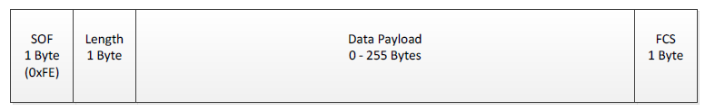
Figure 86. NPI SPI Packet Format
This NPI SPI Frame handles both the delimitation of empty vs non empty data bytes as well as having a fixed length field allowing the SPI master to know how many times the SCLK signal must be toggled to receive a complete message from the SPI slave.
UART
Since UART does not have the same inherent complication as SPI, a much simpler frame format can be used. Because UART RX and TX channels are independent of each other, there is no need for a predefined fixed length field, Furthermore, since there are no empty bytes that must be transmitted, each frame does not need to be delimited. Therefore, every byte received over UART RX or TX channels can be treated as a valid byte of data payload. This allows the NPI UART Frame to consist of only a data payload field:
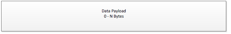
Figure 87. NPI UART Packet Format
Message Types
Both synchronous and asynchronous messages can be supported by NPI. By default,
only asynchronous messages are supported. Support for synchronous messages can
be compiled into NPI using the compiler define NPI_SREQRSP.
Unified NPI
If Unified NPI is being referenced, it will be specifically referred to as “Unified NPI” or (UNPI). Anything that is not specifically called “Unified NPI” is Legacy NPI. However, the API’s and source files of the UNPI implementation will still always be called “NPI”.
Unified NPI offers some improvements over NPI in that it offers a unified frame format that is used by all transport layers. For a UNPI example, see the Simple Network Processor project.
TI provides the source code for UNPI and it can be found in the following files at <SDK_INSTALL_DIR>\source\tiblstacknpi\src\unified
- npi_task.c
- npi_tl.c
- npi_tl_spi.c or npi_tl_uart.c
- npi_util.c
UNPI Architecture
UNPI is implemented as its own TI-RTOS task, and supports inter task communication and routing to the underlying serial interface drivers. See the diagram below for details:
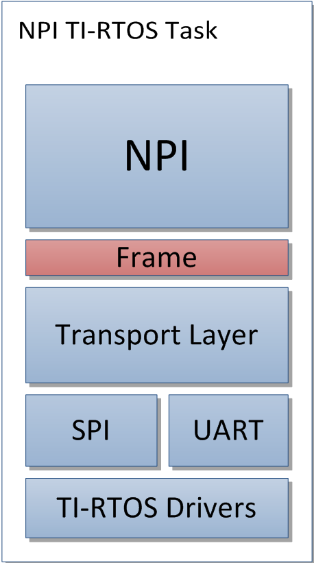
Figure 88. Block Diagram for UNPI
UNPI Signaling
Each processor in an UNPI solution must occupy either the master or slave role. The TI wireless SoC generally occupies the slave role in the network processor examples included in the SDK.
For the remainder of this section, the following terms will be used:
- Application Processor ((AP): UNPI Master (the host MCU)
- Network Processor ((NP)): UNPI Slave (the TI network processor)
In order to properly manage the power domains of the device, there must be a way for an external host to wake the network processor from low power modes. This is done through the inclusion of the following pins:
- Master Ready (MRDY): A GPIO pin whose logic level indicates the state of the master processor. MRDY is an active low (low true) signal. An MRDY event indicates that the master processor is ready to send or receive data.
- Slave Ready (SRDY): A GPIO pin whose logic level indicates the state of the slave processor. SRDY is an active low (low true) signal. An SRDY event indicates that the slave processor is ready to send or receive data.
In the slave role, MRDY is an input pin and SRDY is an output in. In the master role, MRDY is an output pin and SRDY is an input pin.
UNPI Handshake
In order to start an UNPI transaction, there first must occur a handshake sequence using the MRDY and SRDY pins. This handshake is required in order to guarantee that both devices are awake and ready to send and/or receive data. Whichever device first starts the handshake sequence is termed the “initiator”. Either the slave or the master may may be the imitator. The UNPI transaction is completed by the master raising MRDY followed by the slave raising SRDY.
The figures below illustrate both master and slave-initiated UNPI transactions

Figure 89. Timing for Master-Initiated UNPI Transaction
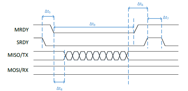
Figure 90. Timing for Slave-Initiated UNPI Transaction
Note
Bidirectional (full-duplex) messaging is also possible with UNPI. See the section below for more details.
Packet Format
The Unified NPI packet format consists of the following fields and is pictured below:
- 1 byte Start of Frame (SOF): always 0xFE
- 2 byte Length field in little-endian format (so LSB first)
- 1 byte Type / Subsystem: that contains both message type and subsystem
information as such:
- Bits[7:5]: Message type, see the message type section for more info
- Bits[4:0]: Subsystem ID field, used to help UNPI route the message to the appropriate place.
- 1 byte command ID: opcode of the command being sent
- variable length Payload: the length of the payload is defined by the length field.
- 1 byte Frame Check Sequence (FCS): calculated by doing a XOR on each byte of the frame in the order they are sent / received on the bus. The SOF byte is always excluded from the FCS calculation.
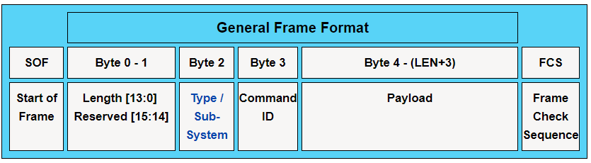
Figure 91. UNPI Packet Format
Message Types
There are three message types supported by Unified NPI. The type of message being sent is often dependent on which processor initiated the transaction. The message types are described below.
| Code | Message Type |
|---|---|
| 0x01 | Synchronous Request (SREQ) |
| 0x02 | Asynchronous Request/Indication (AREQ/AIND) |
| 0x03 | Synchronous Response (SRESP) |
Synchronous Messages
A Synchronous Request ((SREQ)) is a frame, defined by data content instead of the ordering of events of the physical interface, which is sent from the Host to NP where the next frame sent from NP to Host must be the Synchronous Response ((SRESP)) to that SREQ. Once a SREQ is sent, the UNPI interface blocks until a corresponding response (SRESP) is received.
Asynchronous Messages
There are two types of asynchronous messages: asynchronous request ((AREQ)) and asynchronous indication ((AIND)). These messages have the same frame, but the difference lies in whether the transfer was initiated by the network processor (AIND) or the host/application processor (AREQ).
Bidirectional Messaging
There are inherently collisions between messages in any protocol that allows asynchronous messaging (where a signal transition denotes the start of a message as with MRDY and SRDY). Instead of requiring intricate collision handling, the UNPI framework allows for bidirectional messaging to occur. This means that data can be sent from the AP to NP and from NP to the AP in the same message window regardless of the handshake order.
While reducing collision handling, bidirectional messaging adds some complexity to what operations must be performed or initiated by each device. For every AIND the NP initiates, it must prepare to both read and write when MRDY is asserted. For every REQ, the AP must prepare to both read and write once SRDY is asserted. Each device will also need to handle any FIFOs that could potentially be overrun during a message and check at the end of every message to see what, if anything, has been received.
The flow chart for bidirectional message is shown here:
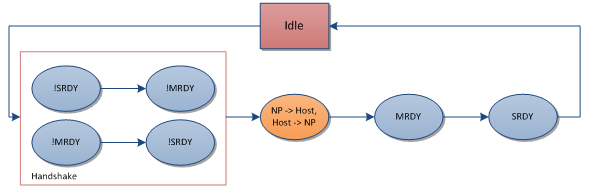
Figure 92. UNPI Bidirectional Flow Chart
Note
Bidirectional messaging is enabled regardless of power savings options
UNPI Usage
Currently, the UNPI protocol has been implemented using the UART and SPI drivers on CC26xx devices. There are certain driver specific settings that should be configured which are defined in the following sections.
Initially, the UNPI task doesn’t initiate the MRDY and SRDY pins; it will let
the pins default to IOID_UNUSED. It is application’s responsibility to define
these pins as such:
UART
To use this configuration, the UART project configuration should be selected
(if available). This configuration allows low power modes through the inclusion
of the MRDY and SRDY signals. If a pre-made project configuration is not
included in the SDK, then NPI_USE_UART must be defined as well as including
the CC26xx UART drivers. If power management is needed, be sure to define
POWER_SAVING and use the MRDY/SRDY signals. The NPI task sets up the UART port
with the following settings:
| Parameter | Default Value |
|---|---|
| Baud Rate | 115200 |
| Data Length | 8 |
| Parity | None |
| Stop Bits | 1 |
| Flow Control | None |
Changing the baud rate can be done in the NPITask_Params_init() function as
below:
SPI
In order to allow full duplex communication, the SPI configuration requires the
use of MRDY and SRDY regardless of whether or not power management is enabled.
In order to use SPI, use the project configuration included in the SDK (if
applicable). If a project configuration is unavailable, then NPI_USE_SPI
should be defined as well as including the CC26xx SPI drivers. If power savings
is needed, be sure to define POWER_SAVINGS.
The NPI task will initialize the SPI with the following parameters
| Parameter | Default Value |
|---|---|
| Bit Rate | 800000 |
| Data Length | 8 |
Changing the bit rate can be done in the NPITask_Params_init() function as
below:
Implementing An NPI Master
As stated above, the TI device operates as an NPI slave in the network processor use case. This means the external MCU must implement the master UNPI role. When developing the NPI master role on an external MCU, there are a couple things to keep in mind:
- The NPI master controls MRDY and thus controls when the NPI frame has completed.
- Even when the slave is sending data, the master must use the payload format to determine how many bytes it expects and raise MRDY when it has received them.
- Since all packets use the same frame format regardless of protocol, the NPI master can use the frame format to determine when to raise MRDY.
An example of an NPI master implementation for UART can be found at <SDK_INSTALL_DIR>\source\tiblstacknpi\src\unified\npi_tl_uart_m.c
Note
NPI_MASTER must be defined as a preprocessor symbol to use the above file.
When toggling MRDY / SRDY it is important to remember the following rules:
- Each device must always initiate a read prior to asserting its respective output pin (MRDY with respect to the AP) regardless of the state of the its respective input pin (SRDY with respect to the AP).
- Each device can only begin to write (or clock data in the case of SPI) once both MRDY and SRDY are asserted.