Congratulations on choosing the SimpleLink™ CC1352R wireless MCU and LaunchPad™ development ecosystem!
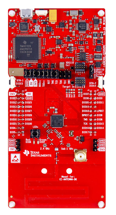
The CC1352R LaunchPad™ (LAUNCHXL-CC1352R1) is a dual-band low power radio kit utilizing the CC1352R which enables Sub-1 GHz + 2.4 GHz in a single chip solution. The CC1352R LaunchPad enables development of wireless applications for the SimpleLink CC1352R wireless MCU supporting proprietary Sub-1 GHz, TI 15.4-Stack for IEEE 802.15.4e/g star based networking (868 MHz, 915 MHz and 2.4 GHz) and Bluetooth low energy (BLE). With multiprotocol support, the CC1352R can run Sub-1 GHz and 2.4 GHz protocols concurrently, including, TI 15.4-Stack, Proprietary Sub-1 GHz, and BLE.
The CC13x2 family of wireless MCUs contain a 32-bit ARM® Cortex®-M4F processor running at 48 MHz as the main application processor, 352 kB of in-system programmable flash memory, 80 kB of low-leakage SRAM, a full complement of peripherals such as I2C, SPI and UART, advanced cryptography accelerators (ECC, AES256, SHA256, etc.) as well as a Sensor Controller Engine (SCE). The SCE is a 2nd programmable processor core ideal for ultra low-power sensor reading and data processing applications. The SCE runs independently from the main Cortex-M4F and handles sensor polling using just a few micro amps of average current. A dedicated Radio Controller (ARM Cortex-M0) handles low-level RF and physical layer (PHY) protocol commands that are stored in ROM or RAM, thus ensuring ultra-low power and great flexibility. A comprehensive list of capabilities can be found in the device data sheet and Technical Reference Manual
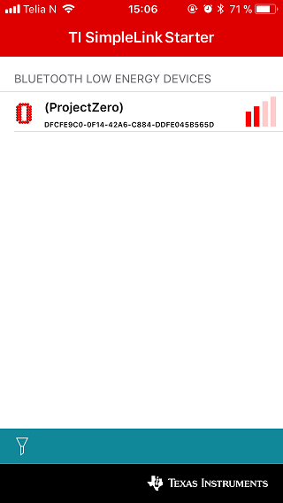
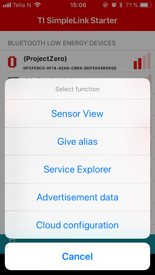
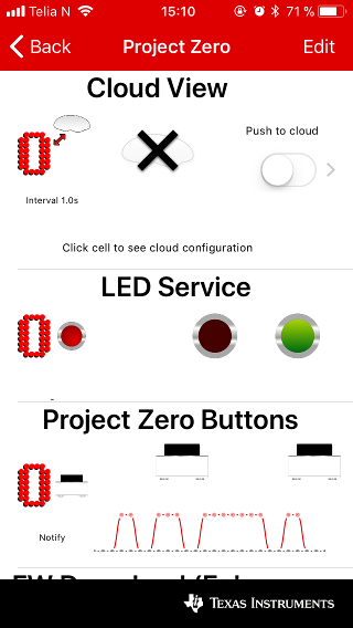
The CC1352R LaunchPad kit is supported by the SimpleLink Starter app for iOS and Android. This app connects your LaunchPad to a smartphone using BLE and supports reading the LaunchPad button states, controlling LEDs and send strings of data to the UART backchannel. It also supports cloud connectivity to the IBM Quickstart server or to any cloud service via MQTT. This enables a cloud view where you can control your LaunchPad from any web browser in minutes after setting it up. Development with the CC1352R LaunchPad is supported by the SimpleLink CC13x2 26x2 SDK containing protocol stack and sample application as well as a wide-range of free development tools such as Code Composer Studio™ (CCS) v7, SmartRF™ Studio and Sensor Controller Studio.
The CC1352R LaunchPad kit can also be upgraded to the latest firmware version or programmed with other wireless protocol demonstration firmware with the over-the-air download (OAD) capability in the SimpleLink Starter app, or programmed directly over USB from a PC using the Uniflash flash programming tool.
- Support for 868 MHz/915 MHz and 2.4 GHz operation
- A passive diplexer connects the antenna to the RF matching networks
- Integrated dual-band PCB antenna for 868 MHz/915 MHz and 2.4 GHz operation
- On-board JTAG emulation tool (XDS110) for flashing & debugging firmware on the target CC1352R device over a micro-USB connection
- EnergyTrace for current measurements
- 40-pin dual-gender BoosterPack™ connectors
- CC1352R wireless microcontroller device
- User red & green LEDs
- 2x User buttons
- Access to all GPIO pins of the CC1352R device
- UART backchannel through the XDS110 for debug/code instrumentation
- 8 Mbit serial (SPI) flash memory
- SMA connector for external antennas (to use the SMA connector move the capacitor C482 to the C483 position. See design files for details.)
EnergyTrace:
EnergyTrace is available on all CC13x2 and CC26x2 LaunchPads. The tool can be used stand-alone as a power profiling tool, or in EnergyTrace++ mode (4-pin JTAG required) within a debug session for state monitoring to help optimize the application for ultra-low-power consumption.
To use EnergyTrace the Power Jumper must be in the XDS110 Power position and the 3V3 jumper on the XDS header must be mounted to provide current to the target. The other jumpers on the XDS header are optional. EnergyTrace does only support 3.3 V supply voltage. Chapter 7 in the Measuring Current Consumption Application Report describes how to run EnergyTrace from CCS.
Power supply requirements:
The LaunchPad is designed to be powered from a USB-compliant power source, either a USB charger or a computer. When used this way, jumpers need to be mounted on the 3V3 position of the central jumper block. An LDO powered from the USB VBUS supply supplies 3.3 V to the XDS110 debugger, the CC1352R, and associated circuitry including the 3V3-marked pins for BoosterPacks.
Temperature range:
The LaunchPad development kit is designed for operation from -25°C to +70°C. Note that other BoosterPack accessories and LaunchPads may have different temperature ranges, and when combined, the combination will be set by the most restrictive combined range. Also, if powering the LaunchPad from an external battery, ensure that you do not exceed the specified operating temperature of the battery.
Out of the Box Demo
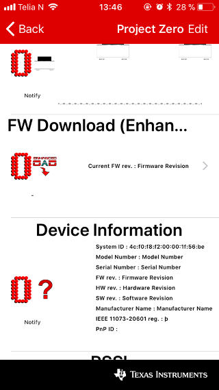
The LAUNCHXL-CC1352R1 is pre-programmed with a Bluetooth 5 (BLE5-Stack) example peripheral project called Project Zero that allows wireless communication with smartphones and tablets over a BLE connection. Follow the few simple steps to get started with your new LaunchPad:


Learn more about Project Zero
Follow the links below to explore the SimpleLink CC1352R MCU SDK in TI Resource Explorer.
Restore the out of box experience
Click the button below to flash your LaunchPad and revert back to the out of the box functionality of your LaunchPad. When the flash tool is complete, it is required to reset the CC1352R by clicking on the reset button (next to the USB port). First time use of this tool will request a plug-in installation for flashing.
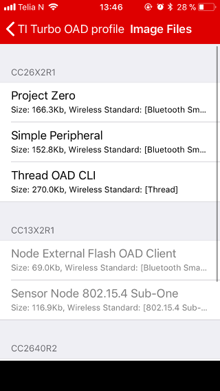
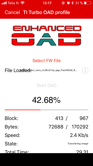
With Project Zero pre-programmed on LAUNCHXL-CC1352R1 you can change the stack with over-the-air download. The new Enhanced OAD lets you try out other compatible stacks in a few steps:
To restore to the factory image, press the left button during boot by:
- Press and hold the left button
- While holding the left button, press and release the reset button (next to the USB connector)
- Release the left button

To get up and running with your own application, head over to SimpleLink Academy which provides a comprehensive set of trainings for the SimpleLink MCU family. The table below shows Project Zero labs for the protocols that are supported by LAUNCHXL-CC1352R1.
| Stack | Lab | Description |
|---|---|---|
| BLE-5 | Bluetooth 5 Fundamentals | Setting up the BLE stack debug environment, connecting to Project Zero, performing basic reading and writing of GATT characteristic data, changing the advertisement/device name. |
| Thread | Thread CLI Project Zero | Introduction to TI-OpenThread using the command line example. |
| TI 15.4 | Sensor and Collector - TI 15.4-Stack Project Zero | Use TI 15.4-Stack and build the sensor and collector examples in order to create a star network. |
| Zigbee | Light and Switch - Zigbee Project Zero | Get started with Zigbee networking by forming a simple Zigbee network. |
| DMM | DMM Fundamentals | Use the Dynamic Multi-protocol Manager (DMM) to let multiple wireless stacks coexist and operate concurrently on one device. |
| Proprietary RF | Basic RX and TX | Use the RF driver, Code Composer Studio and SmartRF Studio to create a proprietary RF link. |
| Sensor Controller | Sensor Controller Fundamentals | Get up and running with the Sensor Controller and Sensor Controller Studio. |
Using the LaunchPad to Debug & Program External Devices
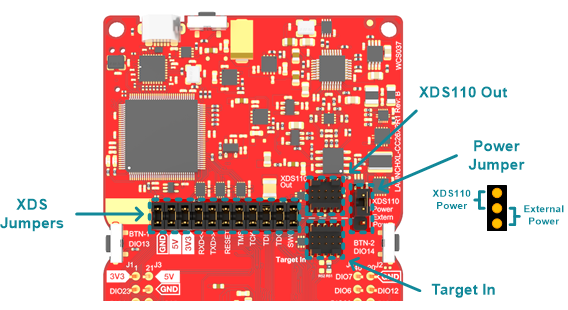
The XDS jumper block in the middle of the board can be used to disconnect the upper section (XDS110 debugger) from the lower section containing the wireless MCU (CC1352R). The jumpers are mounted by default. Which enables the CC1352R to be programmed and debugged by the XDS110.
The onboard XDS110 can be used to debug and program external MCU targets supported by the XDS110 debugger, such as CC13xx and CC26xx wireless MCUs. It is also possible to connect compatible external debuggers to the onboard CC1352R. In either case, all the XDS jumpers on the jumper block must be removed.
With all the jumper block jumpers removed, the XDS110 Out header will work as debug output for the XDS110, and the Target In header will work as debug connector for the CC1352R. The XDS110 output is level shifted and support target voltages between 1.8 V and 3.6 V. If the target board is powered externally, the Power Jumper must be moved to the external power position to set the correct level on the level shifters. The LaunchPad can also power the external board with 3.3 V, then the Power Jumper must be in the XDS110 Power position.
Running the CC1352R from External Power
The CC1352R is by default powered from the LaunchPad's 3.3 V LDO. It is possible to run the device off different supply voltages by disconnecting the 3.3 V jumper and connecting a power supply between 1.8 V and 3.6 V to any of the pins marked 3V3. In this case the Power Jumper must be placed in the Extern Pwr position to connect the external supply to the XDS110 level shifters. Note that even though the supply voltage range of the CC1352R is up to 3.8 V, the maximum voltage in this case is limited by the level shifters at 3.6 V. When measuring current consumption, ensure that the serial (SPI) flash memory is placed into low power mode. Support for placing the serial flash into low power mode is provided in the LaunchPad board file included with the SimpleLink CC13x2 SDK.
CE Compliance
Texas Instruments declares that this product is in compliance with Directive 2014/53/EU. The compliance has been verified in the operating bands of 868 MHz to 868.6 MHz at +14 dBm Tx Power setting and 2402 MHz to 2480 MHz at +5 dBm Tx Power setting. Should you choose to configure the EUT to operate outside of the test conditions, it should be operated inside a protected and controlled environment (such as, a shielded chamber). This evaluation board is only for development and not an end product. Developers and integrators that incorporate the chipset in any end products are responsible for obtaining applicable regulatory approvals for such end product.
REACH Compliance
In compliance with the Article 33 provision of the EU REACH regulation we are notifying you that this module includes a Crystal 32.768KHz, Mfg PNo: FC-135 32.7680KA-AG0 from Epson that contains a Substance of Very High Concern (SVHC) above 0.1%. These uses from Texas Instruments do not exceed 1 ton per year. The SVHC is Lead titanium trioxide CAS# 12060-00-3.