Introduction
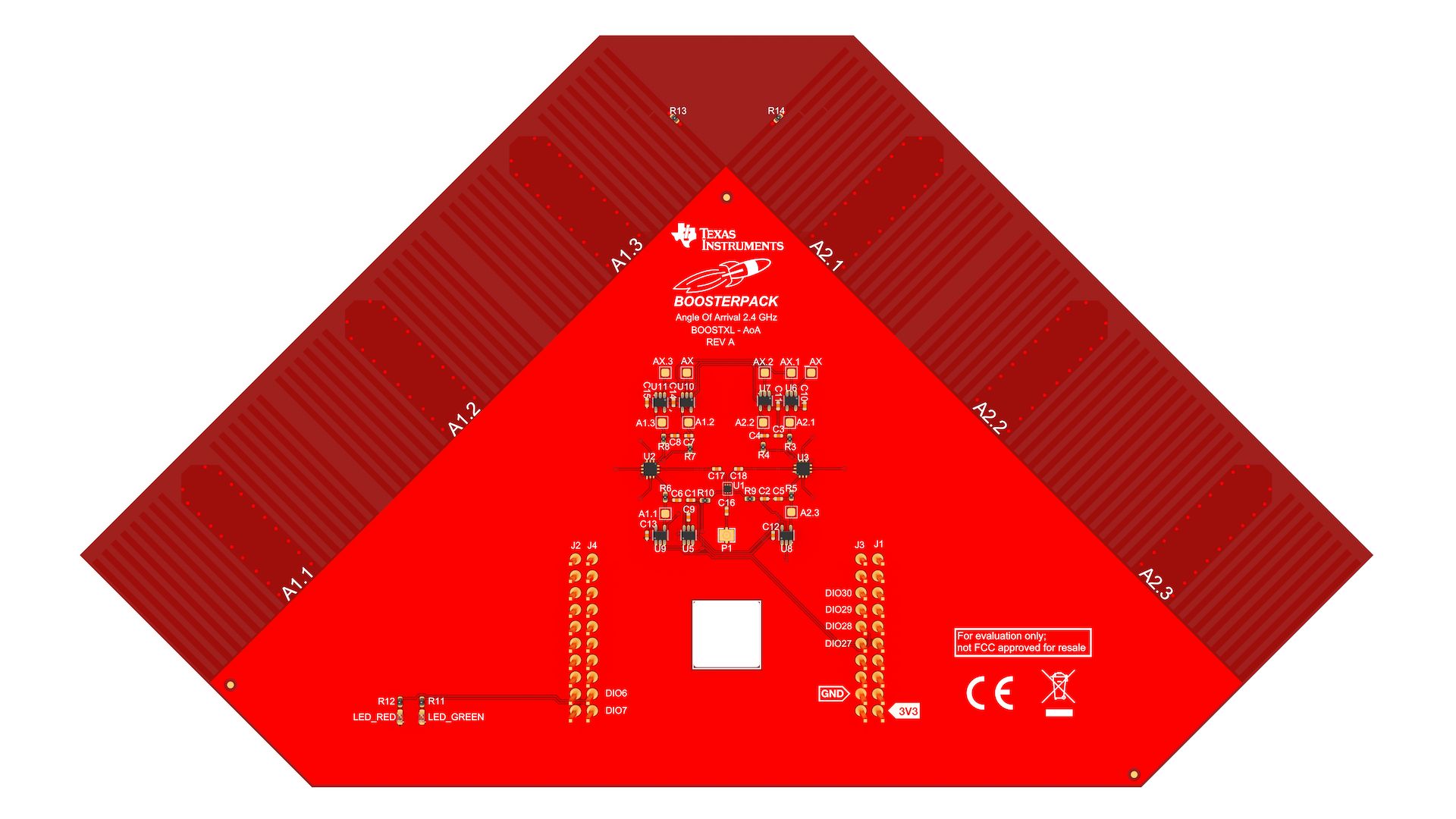
The Angle of Arrival BoosterPack™ kit (BOOSTXL-AOA) is an easy-to-use plug-in module equipped with antenna arrays suitable for evaluation of Angle of Arrival applications. The 2 orthogonal antenna arrays each consist of 3 dipole antennas tuned for operation at 2.4 GHz. The antennas are selected with RF switches and then connected to a single JSC connector. The JSC Series connector is used to connect to an AoA compatible RF receiver like the CC2640R2 LaunchPad™.
Key Features
- Two antenna arrays with three 2.4 GHz dipole antennas on each
- RF switches to switch between the different antennas
- JSC RF connector
- Two LEDs
What's Included
- 1x BOOSTXL-AoA
- 1x 100 mm JSC to JSC RF cable
- 1x Quick Start Guide
Requirements
BOOSTXL-AoA is designed to be used with the CC2640R2 LaunchPad and are following
the BoosterPack™
Module Pinout Standard.
The BOOSTXL-AoA board contains two orthogonal arrays, each with three dipole antennas.
Each antenna array can theoretically cover an angle on the incoming signal up to ±90°. When using both arrays combined, a coverage of up to ±135° is achievable
(The two antenna arrays overlap 45° on each side).
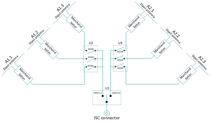
Dipole antennas are by nature differential and needs to be fed with a balanced signal.
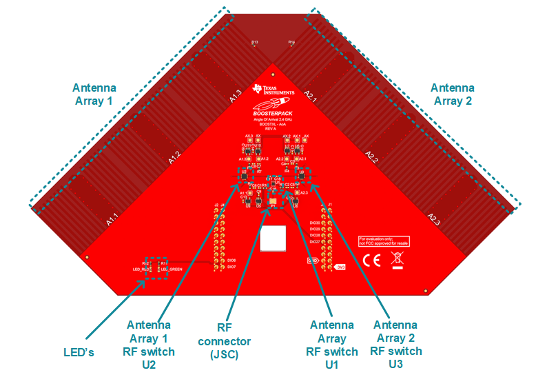
A balanced signal is created using a marchand balun that is integrated in the PCB. The single ended side of the baluns are fed to the antenna switches (U2 and U3).
The array switch, U1, is used to connect each array to the JSC connector.
Block schematic
Schematic
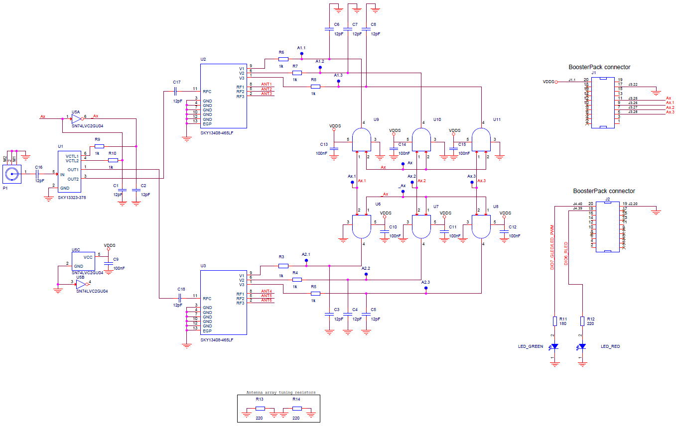
The three RF antenna switches (U1, U2 and U3) are controlled by DIO27 to DIO30. The control logic is shown in the table below.
Truth table
| DIO27 | DIO28 | DIO29 | DIO30 | Antenna |
|---|---|---|---|---|
0: 0.0V to 0.2V, 1: 2.5V to 5.0V
LEDs
The RED and GREEN LEDs are connected to DIO6 (RED) and DIO7 (GREEN) as on the CC2640R2 LaunchPad.
Design files
BOOSTXL-AoA design files can be found here.
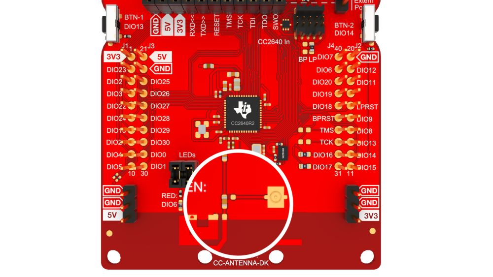
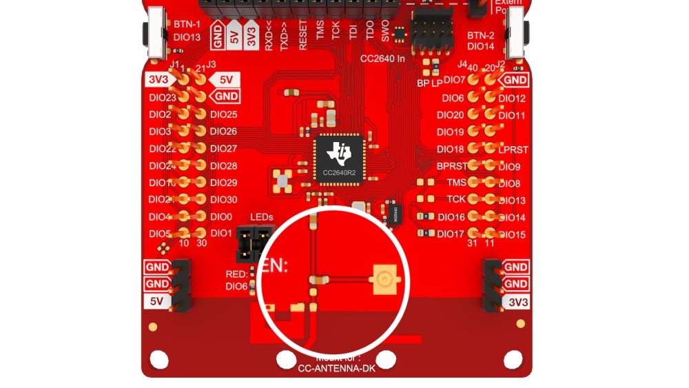
1. Configure the LaunchPad for external antenna
To use a CC2640R2 LaunchPad with BOOSTXL-AoA, the LaunchPad must be configured to use external antenna.This is done by moving capacitor C51 according to the rightmost image below.
|
|
2. Connect JSC RF cable
Connect the included JSC cable from the LaunchPad JSC connector to the BOOSTXL-AOA JSC connector.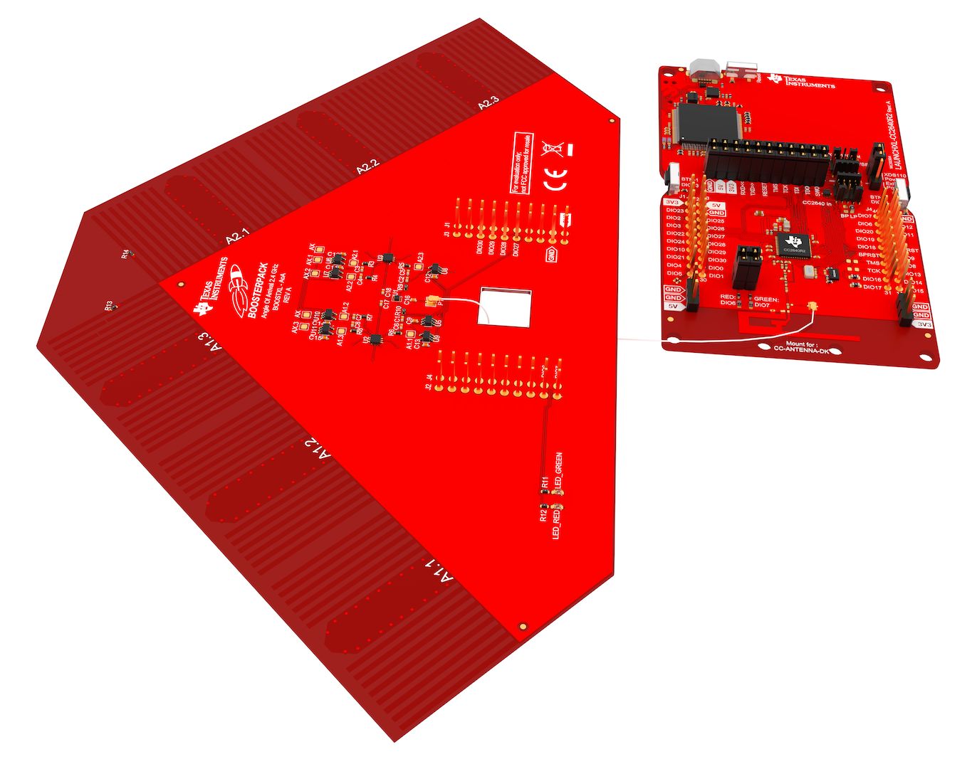
3. Mount BOOSTXL-AoA on top of the CC2640R2 LaunchPad
Make sure that all 40 BOOSTXL-AOA pins are aligned and connected to the 40 pins on the LaunchPad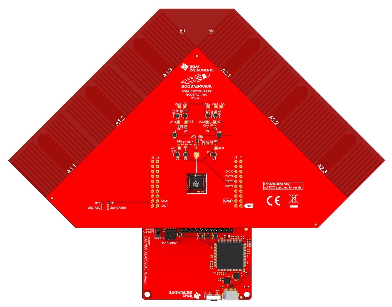
Test setup for measuring AoA performance on a BOOSTXL-AoA in an anechoic RF chamber can be seen below.
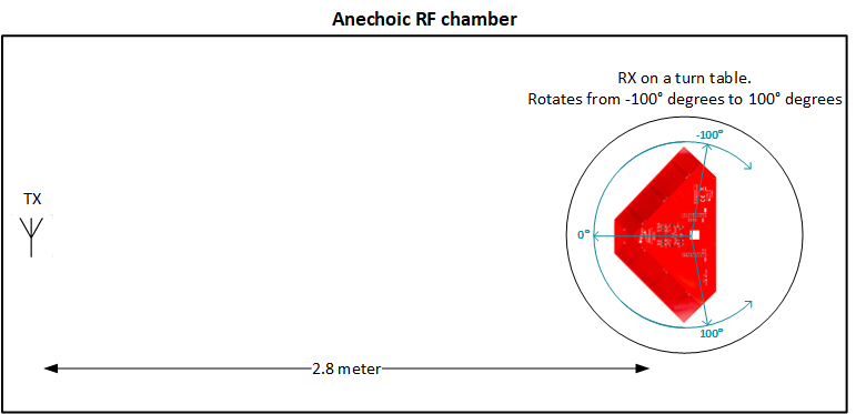
The AoA transmitter is placed 2.8m from the AoA receiver and the board is rotated so that the incoming signal arrives at angles (phi) from -100° to 100° degrees.
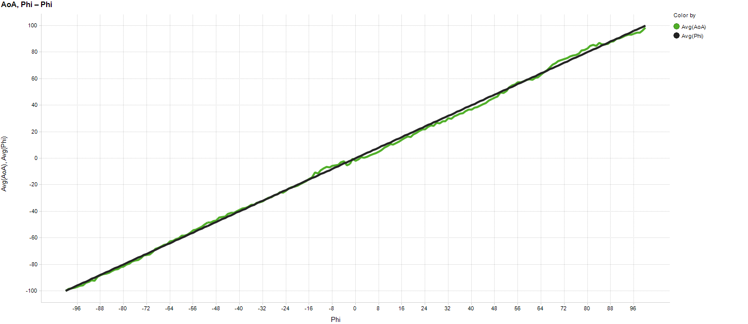
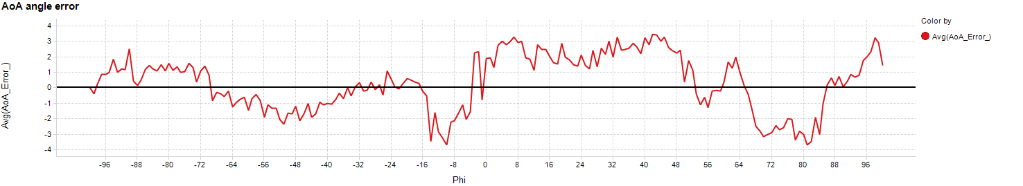
The AoA angle error graph shows the difference between the true angle on the incoming signal (phi) and the measured AoA.
Challenges
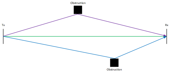
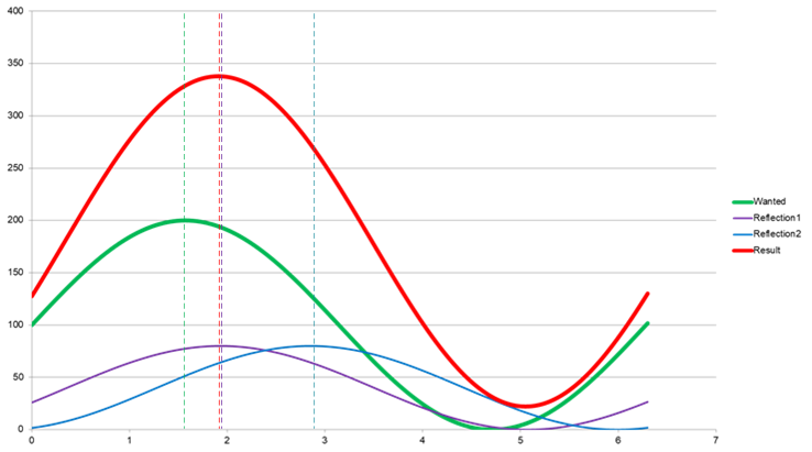
When operating in a non-ideal environment the biggest challenge is multipath propagations where the signals are coherent.Coherent signals are signals having the same frequency but not necessarily the same phase. Coherent signals can be the orginal signal reflected from walls or other obstructions and are appearing slightly delayed at the receiver since the signal have traveled a longer distance. Since the signal have traveled longer it will also have a different phase than the orginal signal.
The graphs below gives a simplified view of what happens when multipath propagations with coherent signals are received. Green is the wanted signal while red is the signal seen by the receiver.
Before starting developing Angle of Arrival applications it's recommended to read the Localization Toolbox section of the
BLE-Stack User's Guide
Software examples for the Angle of Arrival BoosterPack™ kit
(BOOSTXL-AOA) used together with a CC2640R2 LaunchPad can be found in the
CC2640R2 SDK (v2.40.00.xx or newer).

Power supply
The BoosterPack is designed to be powered from the 3V3 supply of a compatible LaunchPad through the BoosterPack connector.
Temperature range
The BoosterPack is designed for operation from -40°C to +85°C. Note that other BoosterPack accessories and LaunchPads may have different temperature ranges, and when combined, the combination will be set by the most restrictive combined range.