Introduction
This module is an advanced study of the Over the Air Download (OAD) feature of the TI BLE-Stack. The estimated time to complete this lab is between 1-2.5 hours. It is assumed that the reader has a basic knowledge of embedded C tool chains and general C programming concepts. This lab is intended as additional material for users who are already familiar with the OAD concepts presented in the OAD Chapter of the BLE-Stack User's Guide.
OAD refers to the ability for an image to download a new executable image, over the air using the BLE protocol stack. A number of software components are involved in this process and TI uses OAD to refer to all of them as a software system.
First, the lab will cover an overview of a typical BLE-Stack image and examine
the high level anatomy of an OAD image. The next task will be running the out of
the box demo for OAD using BTool, highlighting critical concepts along the way.
After the user is comfortable with performing an OAD, the lab will cover adding
OAD to an existing project, using multi_role as an example. The lab will
conclude with a study of OAD debugging techniques and explain how to avoid
common OAD pitfalls. As a bonus, the lab will review how to create an OAD
production image.
Prerequisites
Software for desktop development
- CCS or IAR installed with support for CC13xx/CC26xx devices.
- BTool, this will come bundled with one of the SDKs below.
See the
tools/blestack/btoolfolder. - Newest SimpleLink™ CC2640R2 SDK(http://www.ti.com/tool/SIMPLELINK-CC2640R2-SDK)
- SRecord
- UNIFLASH
Hardware
This module requires the following kits:
Recommended reading
- BLE Fundamentals and Custom Profile labs
OAD Documentation
It is recommended to review the OAD Chapter of the BLE-Stack User's Guide before starting this lab.
Getting started – Desktop
Install the Software
Run the SimpleLink SDK installer. This gives you the SDK with TI-RTOS included
at the default location C:\ti\simplelink_cc2640r2_sdk_x_xx_xx_xx.
Additionally, for flashing hex files UNIFLASH will be needed
Modify/Load the Software
Load Board #1
Load the first board with the host_test sample application that will enable communication with BTool.
The host_test project is can be found as a precompiled hex file in the blestack examples folder, e.g. <SimpleLink SDK> → examples → rtos → <board> → blestack → hexfiles → cc2640r2lp_host_test.hex.
Load Board #2
Load the second board with simple_peripheral_oad_offchip project that supports OAD. The simple_peripheral_oad_offchip project is found in the blestack examples folder, e.g. <SimpleLink SDK> → examples → rtos → <board> → blestack → simple_peripheral_oad_offchip → tirtos.
Loading the hex file
OAD enabled projects require special care when loading the files. This is explained later in the lab, for now you can setup simple_peripheral_oad_offchip by performing the following steps:
- import simple_peripheral_oad_offchip into the workspace, build the BIM, stack, app (in that order)
- Load the BIM directly using CCS
- Navigate to the output folder of the app project and use UNIFLASH to load
simple_peripheral_cc2640r2lp_oad_offchip_app_FlashROM_oad_merged.bin - Use offset = 0x00000000, and select the type as binary
Additionally, later in the lab we will use the following projects:
multi_role
- <SimpleLink SDK> → examples → rtos → <board> → blestack → multi_role → tirtos.
Building the projects
Be sure to build both the stack and application before loading projects.
As detailed in the introduction, the following tasks will cover some of the primary topics related to OAD using the BLE-Stack.
Anatomy of an OAD
This section seeks to explain the various components involved in an OAD image from a high level. Each software component will be treated as a building block that is added to a vanilla BLE-Stack image to eventually build an OAD image.
Default Non OAD Image
We will begin with the template for a standard BLE-Stack image that does not have OAD enabled.
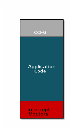
There are three main components of this image:
- The instructions/constants that implement the compiled form of the program (application code)
- The reset vectors in the ARM Cortex M format: ARM Cortex M3 Vector Table
- The CCFG, which contains chip configuration parameters, see the Technical Reference Manual
These three components are required for any image that is to run on the CC2640R2F. The goal of OAD is to get an executable image of this form on the device via an over the air update, no JTAG or wires required.
However, in order to achieve the goal of making the image pictured above upgradeable over the air, a few software components must be set in place.
Image Fragmentation/ Image Header
Even with the largest payload size supported by the Bluetooth Low Energy Specification, an entire CC2640R2 image cannot be sent in an single packet. Therefore, the image to be sent over the air must be fragmented into a size that will fit into BLE GATT payloads.
The figure below pictures fragmentation of the stock image into GATT payloads.
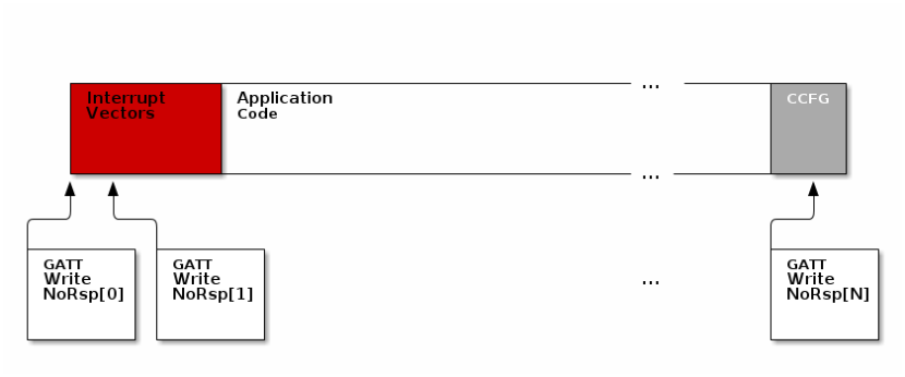
It can be seen from the figure above, that it will take many GATT packets to send a complete image over the air using the BLE protocol. Each of these packets containing OAD image information is referred to as an OAD Block.
However, there is no way for the receiving device to know information about the image that is coming via OAD, valuable information such as image version, image, size, and image type must be stored in the image. Preferably this information will be known at the beginning of the download session so that OAD Target (device receiving the image) can make decisions based on the data describing the image. The image header solves this problem. The OAD image header is a collection of metadata that describes the image. The image header is useful for the following purposes:
- Image metadata is bundled as part of the image
- A running image can query knowledge about itself by reading the header
- Bootloader software can read the header to determine which image(s) are present and active
- Information about the incoming image is available to the target early in the OAD process.
Now, that we are sold on the benefits of an image header in an OAD system, here is an updated drawing of the stock image with an image header added.
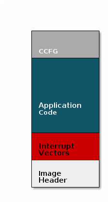
Comparison: Image with and without header
The space available to the code section of the image is shrunk to accommodate
the header, and the reset vectors are pushed back to accommodate the header.
These changes are specified in the linker script (shrinking app space) and the
RTOS .cfg file (relocating reset vectors).
Why is an image header needed for OAD? (Select all that apply)
Boot Image Manager (BIM)
A running image cannot update itself. This means that incoming OAD image must be stored in a temporary location while it is being received. This temporarily location can be a reserved location in internal flash outside of the executable area covered in the first image. Alternatively, the temporary location can be in an external flash chip
After the download is complete, some code must determine if the new image is valid, and if current image should be overwritten, and finally execute the new image.
This piece of code is referred to the Boot Image Manger (BIM) in the TI OAD solution.
BIM is intended to be permanently resident on the device, meaning it persists through many OADs and cannot be updated.
BIM will run every time the device boots and determine if a new image should be loaded and run (based on image header).
Furthermore, the BIM and CCFG structure are tied together, because both are required for a successful device boot.
The CCFG is needed by the boot ROM and startup firmware for device trim and to
determine where program execution is to start from. By default the boot ROM will
jump to address 0x00000000 and look for a vector table, but this region is
now occupied by the image header. A custom CCFG must be used to instruct the
device to jump directly to the BIM.
From there the BIM will perform device trim based on the CCFG settings, and determine and load the optimal image based on the OAD image header.
The BIM code will require more reserved space in our system. See below for the memory map after a BIM has been added to the last image.
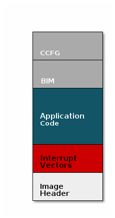
CCFG and BIM
The BIM is responsible for linking and defining the CCFG structure, instead of the application as in the non OAD case. This ensures that the device will always execute the BIM after boot.
Should the file ccfg_app_ble.c be included and linked as part of the application?
OAD Protocol/ BLE Profile
Currently we have covered all the necessary building blocks for updating an image local to the target device. The only missing piece is a vehicle for sending the OAD blocks over the air, and storing them on the target device.
This functionality is implemented in the BLE-Stack OAD profile. As covered in the Custom Profile lab, the GATT profile is the vehicle for sending data over BLE.
At a high level, the BLE-Stack OAD profile is responsible for receiving the following
- Determining if the candidate image should be accepted for download
- Receiving and unpacking image blocks and storing them
- Writing the received blocks to non volatile storage
- Verifying the received image post download
The OAD profile is implemented in the oad.c file and its associated flash
wrappers. Later, the module will cover the steps required to add the OAD
profile to a project.
Does the image updated via OAD need to contain OAD related services in order for subsequent OADs to work?
OAD Security
By default, all OAD images and some OAD commands must be signed by a trusted peer. This means that in order to initiate an OAD session, the image identify command must be signed by the OAD Distributor. Before accepting the download, the OAD Target will verify the signature in the Image Identify command using the Elliptic Curve Digital Signature Algorithm (ECDSA) with the public keys installed on the device. If the signature is verified to be from a trusted peer, then the OAD session will begin.
After the OAD download is complete the BIM will also validate the signature of the entire binary image and ensure that it is valid before loading and running the image.
The demos in the SDK use a default public key that is installed in the BTool distribution as well as the OAD Target images. This key is for evaluation purposes only. Without matching keys installed on the OAD Distributor and OAD Target, secure OAD sessions will be rejected.
Unsecure OAD is still supported by the SDK, switch the app, stack, and BIM
projects to use the _unsecure build configuration to enable unsecure OAD. Be
sure that all projects are using matching configurations (secure vs unsecure)
for consistent behavior.
Installing non-default security keys
The default security keys must be changed before deploying a secure OAD product using the TI solution. Each SDK ships with these keys installed by default so using the default keys presents a serious security risk.
Changing the keys is detailed in the BLE-Stack User's Guide
- Over the Air Download → OAD Image Tool → Generating new security keys (Embedded)
- Over the Air Download → Performing an OAD → Generating new security keys (BTool)
Task 1 – Running the OAD Demo
The BLE-Stack User's Guide has two sections dedicated to performing an BLE OAD using BTool.
First, you will need to setup the OAD environment by flashing the devices with
their required images and initializing them properly. These steps are covered by
the Setting up the BLE OAD Environment Chapter. Follow the steps in the guide to
prepare for an OAD. Use the simple_peripheral_oad_offchip
FlashROM_Release_unsecure configuration as the sample application.
You must build the simple_peripheral_oad_offchip project and the
cc26x2r1lp_bim_offchip project with the *_unsecure configuration because the
project_zero project builds without security.
BIM Security
When performing OAD you are not allowed to switch between secure and unsecure images. This is due to the fact that the BIM is persistant between OAD updates. The BIM is only built to facilitate the upgrade of either secure or unsecure images. The BIM cannot facilitate the upgrade of a secure image into an unsecure image.
Loading image with signature
When using secure OAD, the BIM will not accept images that are loaded straight
from the IDE. These images will run while the debugger is attached, but will
not run after reset.
This is because the oad_image_tool must run over the binary
to place the signature in the image and BIM will not accept images without
a signature.
To be sure that the image runs after reset, use uniflash to load the
simple_peripheral_cc2640r2lp_oad_offchip_app_FlashROM_oad_merged.bin
image on the device. Do this after loading the BIM.
To ensure that Halt in Boot does not occur, unplug and replug the device from USB power after flashing.
Navigate to the the file oad_image_header.h and change the field SOFTWARE_VER
to indicate a hypothetical version 2 of the app. Remember, that the upper two
bytes in the SOFTWARE_VER field are reserved for the stack version and the
bottom two are reserved for the app version.
Rebuild the app, but do not load it on the device.
Instead, follow the steps detailed in the BLE-Stack User's Guide chapter titled Performing an OAD. Once the upgrade is complete the device should reboot and display SBP Off-chip OAD v0002 on the terminal.
At this point you will have upgraded our application using OAD.
For a more advanced exercise, try changing the color of the LED that blinks when the app starts up.
In the OAD ecosystem, BTool and host_test image combined together fulfill which role?
Select all of the following that are true about OAD Target devices.
Task 2 – Add OAD to Multi Role
This section will detail how to add BLE OAD to an existing project. The intention is to start with an unmodified sample app from the SDK that does not currently use OAD, and add OAD to it.
Customers can use this section to add OAD to their existing projects. The example project used to demonstrate these steps will be multi_role.
Converting from Stack Library to Split Image
multi_role and most other projects in the SDK will build the stack as a
statically linked library. This is different than the OAD projects which build
the stack as a separately linked executable image. The reason for using the
split image configuration with OAD is to enable independent update of the stack
and app images. Merged image update is also possible with the app and stack
images merged into a single binary.
First, we will cover the steps required to convert multi_role from a
stack_library image to a split image configuration.
Adding OAD to the stack
As part of the steps below we will convert the stack project to a split image and add OAD to it.
Change the ouput of the stack project to be executable. This cannot be done via the GUI after project has been imported. Instead, navigate to <SimpleLink SDK> → examples → rtos → <board> → blestack → multi_role → tirtos → ccs → multi_role_cc2640r2lp_stack_library.projectspec. Delete the following line:
outputType="staticLibrary"Now import the multi_role app project. This will auto import the stack project. The output type should show as executable for both app and stack.
Remove the following compiler defines
STACK_LIBRARY: This will make the stack a split imageGATT_NO_CLIENT: Multi role is a GATT client and this feature needs to be built into the stack
Add the following compiler defines
SPLIT_APP_STACK_IMAGE: Inform OAD that a split image configuration should be usedSECURITY: Inform OAD that security is to be used, only needed if secure OAD
Add Frontier, Hex Output, and the oad_image_tool as post build steps
The following should be used with secure OAD (i.e.
SECURITYdefined):${CG_TOOL_HEX} -order MS --memwidth=8 --romwidth=8 --intel -o ${ProjName}_${ConfigName}.hex ${ProjName}.out ${TOOLS_BLE_DIR}/frontier/frontier ccs ${PROJECT_LOC}/${ConfigName}/${ProjName}_linkInfo.xml ${WORKSPACE_LOC}/multi_role_cc2640r2lp_stack_library/TOOLS/ccs_compiler_defines.bcfg ${WORKSPACE_LOC}/multi_role_cc2640r2lp_stack_library/TOOLS/ccs_linker_defines.cmd ${TOOLS_BLE_DIR}/oad/oad_image_tool ccs ${PROJECT_LOC} 2 -hex1 ${ConfigName}/${ProjName}_${ConfigName}.hex -k ${TOOLS_BLE_DIR}/oad/private.pem -bdf ${WORKSPACE_LOC}/multi_role_cc2640r2lp_stack_library/TOOLS/ccs_compiler_defines.bcfg -o ${WORKSPACE_LOC}/multi_role_cc2640r2lp_stack_library/${ConfigName}/${ProjName}_${ConfigName}_oadThe following should be used with unsecure OAD (i.e. no
SECURITYdefined):${CG_TOOL_HEX} -order MS --memwidth=8 --romwidth=8 --intel -o ${ProjName}_${ConfigName}.hex ${ProjName}.out ${TOOLS_BLE_DIR}/frontier/frontier ccs ${PROJECT_LOC}/${ConfigName}/${ProjName}_linkInfo.xml ${WORKSPACE_LOC}/multi_role_cc2640r2lp_stack_library/TOOLS/ccs_compiler_defines.bcfg ${WORKSPACE_LOC}/multi_role_cc2640r2lp_stack_library/TOOLS/ccs_linker_defines.cmd ${TOOLS_BLE_DIR}/oad/oad_image_tool ccs ${PROJECT_LOC} 2 -hex1 ${ConfigName}/${ProjName}_${ConfigName}.hex -bdf ${WORKSPACE_LOC}/multi_role_cc2640r2lp_stack_library/TOOLS/ccs_compiler_defines.bcfg -o ${WORKSPACE_LOC}/multi_role_cc2640r2lp_stack_library/${ConfigName}/${ProjName}_${ConfigName}_oadAdd the following libraries to be input to the linker
${SRC_BLE_DIR}/../../../source/ti/devices/cc26x0r2/driverlib/bin/ccs/driverlib.lib
${WORKSPACE_LOC}/${ProjName}/${ConfigName}/lib_linker.cmd
${WORKSPACE_LOC}/${ProjName}/${ConfigName}/ble_r2.symbols
${SRC_BLE_DIR}/common/cc26xx/ccs/cc26xx_stack_oad.cmd
Add the following defines to the linker
CC26X0ROM=2
OSAL_SNV=2
PAGE_ALIGN
Change the entry point of the application to
startup_entrySuppress the following benign errors
16002-D
10247-D
10325-D
10229-D
16032-D
At this time, the stack should build and link cleanly, but the oad_image_tool step should fail
Add the following file to the
Startupfolder in the stack project. You can find this file at <SimpleLink SDK> → source → ti → blestack → profiles → oad → cc26xxoad_image_header_stack.c: Stack definition of image header.
Add the following to the include options
${SRC_BLE_DIR}/profiles/oad/cc26xx
Change the number NV Pages used by OAD.
- Navigate to <SimpleLink SDK> → source → ti → blestack → profiles → oad → cc26xx
- Open
oad_image_header.hand change the defineOAD_NUM_NV_PGSto 2. - This change is required because
multi_roleusesOSAL_SNV=2 - The
OAD_NUM_NV_PGSandOSAL_SNVsettings must be in sync
Open
multi_roleproject and go to cc2640r2lp_stack project.
Navigate to <General Options> → Output → Then change the output file from Library to Executable.Change Debugger Setting
The default IAR debugger setting in cc2640r2lp_stack is set to Simulator, so you need to change it to use TI XDS. Then under TI XDS, you make sure the Emulator is set to TI XDS110 Emulator in order to program the cc2640r2lp_stack to the device.
Remove the following compiler defined symbols
STACK_LIBRARY: This will make the stack a split imageGATT_NO_CLIENT: Multi role is a GATT client and this feature needs to be built into the stack
Add the following comipler defined symbols
SPLIT_APP_STACK_IMAGE: Inform OAD that a split image configuration should be usedSECURITY: Inform OAD that security is to be used, only needed if secure OAD
Add Frontier, Hex Output, and the oad_image_tool as post build step
The following should be used with secure OAD (i.e.
SECURITYdefined):cmd /C "$TOOLS_BLE_DIR$\frontier\frontier.exe iar $PROJ_DIR$\$CONFIG_NAME$\List\$TARGET_BNAME$.map $PROJ_DIR$\..\config\iar_boundary.bdef $PROJ_DIR$\..\config\iar_boundary.xcl & $TOOLS_BLE_DIR$\oad\oad_image_tool.exe --verbose iar $PROJ_DIR$ 2 -hex1 $EXE_DIR$\$TARGET_BNAME$.hex -bdf $PROJ_DIR$\..\config\iar_boundary.xcl -k "$TOOLS_BLE_DIR$\oad\private.pem" -o $EXE_DIR$\$TARGET_BNAME$_oad"The following should be used with unsecure OAD (i.e. no
SECURITYdefined):cmd /C "$TOOLS_BLE_DIR$\frontier\frontier.exe iar $PROJ_DIR$\$CONFIG_NAME$\List\$TARGET_BNAME$.map $PROJ_DIR$\..\config\iar_boundary.bdef $PROJ_DIR$\..\config\iar_boundary.xcl & $TOOLS_BLE_DIR$\oad\oad_image_tool.exe --verbose iar $PROJ_DIR$ 2 -hex1 $EXE_DIR$\$TARGET_BNAME$.hex -bdf $PROJ_DIR$\..\config\iar_boundary.xcl -o $EXE_DIR$\$TARGET_BNAME$_oad"Add the following libraries to be input to the linkerExtra Options
-f $PROJ_DIR$\..\config\lib_linker.cmdChange the linker file
$SRC_BLE_DIR$\common\cc26xx\iar\cc26xx_stack_oad.icfNote
It is also recommended to remove the cc26xx_stack.icf from the Tools folder and drag cc26xx_stack_oad.icf into Tools folder
Make sure the following defines to the linker are present.
FLASH_ROM_BUILD=2
CC2650=2
OSAL_SNV=2
At this time, the stack should build and link cleanly, but the oad_image_tool step should fail
Add the following file to the
Startupfolder in the stack project. You can find this file at <SimpleLink SDK> → source → ti → blestack → profiles → oad → cc26xxoad_image_header_stack.c: Stack definition of image header.oad_image_header.h: Stack definition of image header.
Add the following to the include options
$SRC_BLE_DIR$\profiles\oad\cc26xx
Change the number NV Pages used by OAD.
- Navigate to <SimpleLink SDK> → source → ti → blestack → profiles → oad → cc26xx
- Open
oad_image_header.hand change the defineOAD_NUM_NV_PGSto 2. - This change is required because
multi_roleusesOSAL_SNV=2 - The
OAD_NUM_NV_PGSandOSAL_SNVsettings must be in sync
Adding OAD to the application project
In order to add OAD, certain files and include paths should be added to the project, these are detailed in the list below.
Change the linker file
Edit the line that contains references to
cc26xx_app.cmdand replace them withcc26xx_app_oad.cmd.Remove the stack library file and add the boundary file to the linker.
Remove the following lines:
 ${REF_PROJECT_1_LOC}/FlashROM_Library/ble_r2.symbols
 ${REF_PROJECT_1_LOC}/FlashROM_Library/lib_linker.cmd
 ${REF_PROJECT_1_LOC}/FlashROM_Library/${REF_PROJECT_1_NAME}.lib
Add the following lines This must go before cc26xx_app_oad.cmd:
 ${SRC_BLE_DIR}/rom/ble_rom_releases/cc26xx_r2/Final_Release/common_r2.symbols
 ${WORKSPACE_LOC}/multi_role_cc2640r2lp_stack_library/TOOLS/ccs_linker_defines.cmd
In most cases you can replace the .lib reference with the
ccs_linker_defines.cmd, just be sure that it is beforecc26xx_app_oad.cmdin the list. This is because link order matters, and symbols from theccs_linker_defines.cmdare needed incc26xx_app_oad.cmd.Add the following to the linker defines:
OAD_IMG_E=1: Tell the linker that off-chip OAD is to be used
Add the following compiler defines:
MAX_PDU_SIZE=251: Build the stack with a large MTU size to enhance OAD throughputSPLIT_APP_STACK_IMAGE: Tell OAD that a split image configuration is to be usedSECURITY: (optional) Enable OAD ECDSA image and command verificationOAD_BLE_SECURITY: (optional) makes characteristics in the OAD profile require an authenticated BLE link before they can be written to.Change the following define to 1 for now to reduce RAM usage
MAX_NUM_BLE_CONNS=1
Changing PDU Size
This define will control the negotiated block size. Block Size is derived from MTU size, which is derived by the minimum of the local supported PDU size and peer's supported MTU. Refer to the notes about OAD Block size in the BLE-Stack User's Guide (Over the Air Download (OAD) → BLE-Stack OAD Profile → OAD Block Size Rules)
Maximum supported ble connections
When enable split image and add OAD into the project, the available RAM usage decreases. In order to support more than 1 connection, you need to enable CACHE_AS_RAM for both BIM and app project. You can also tune the MAX_PDU_SIZE to increase the available RAM usage with the trade of OAD speed. Please find the BLE-Stack User's Guide. (Developing a Bluetooth Low Energy Application → Memory Management → Using the Cache as RAM)
Remove the following compiler defines:
STACK_LIBRARY
Add the following command files to the compiler input:
${WORKSPACE_LOC}/multi_role_cc2640r2lp_stack_library/TOOLS/ccs_compiler_defines.bcfgAdd the following cfgArgs to the project.
{NO_ROM:0, OAD_IMG_E:1}This will Relocate the TI-RTOS reset vectors via arguments to the
cc2640_r2_csdk.cfg fileThe following file should be removed from the project:
ccfg_app_ble.c(in Startup folder) : The BIM links the CCFG in an OAD system.
Add the following files to the project. These files can be found in the following locations:
<SimpleLink SDK> → source → ti → blestack → profiles → oad → cc26xx
<SimpleLink SDK> → source → ti → blestack → common → cc26xx → crc
<SimpleLink SDK> → source → ti → blestack → common → cc26xx → flash_interface
<SimpleLink SDK> → source → ti → blestack → common → cc26xx → bimoad.c: OAD profile implementationoad.h: Public OAD profile API definitioncrc32.c: CRC32 algorithm and helper functionscrc32.h: CRC32 public API definitionflash_interface.h: A flash abstraction layer that abstracts flash operations for on and off-chip OAD.oad_image_header.h: Structure definitions for the OAD image headeroad_image_header_app.c: Application definition of image header.bim_util.h: Public API definition of utility functions shared between the BIM and application.bim_util.c: Implementation of BIM utility functionsflash_interface_ext_rtos.c: TI-RTOS implementation of flash interface for off-chip OAD.ExtFlash.c: SPI interface to external flash.ExtFlash.h: SPI interface to external flash.find_stack_entry.h: Public API definition for stack entry location switch.find_stack_entry.c: Used to locate the app/stack boundary in split image OAD scenarios.
The following pre-processor include paths should be added to the project
${PROJECT_LOC}/OAD: This assumes you have place all the files from step 5 in a folder titled "OAD"${SRC_BLE_DIR}/common/cc26xx/flash_interface/external${SRC_BLE_DIR}/common/cc26xx/crc${SRC_BLE_DIR}/common/cc26xx/bim${SRC_BLE_DIR}/profiles/oad/cc26xx${SRC_BLE_DIR}/
Add the OAD image tool post build step to the project. Be sure to not delete the existing hex file step. Place the OAD step after it!
The following should be used with secure OAD (i.e.
SECURITYdefined)${TOOLS_BLE_DIR}/oad/oad_image_tool ccs ${PROJECT_LOC} 1 -hex1 ${ConfigName}/${ProjName}.hex -k ${TOOLS_BLE_DIR}/oad/private.pem -bdf ${WORKSPACE_LOC}/multi_role_cc2640r2lp_stack_library/TOOLS/ccs_compiler_defines.bcfg -hex2 ${WORKSPACE_LOC}/multi_role_cc2640r2lp_stack_library/FlashROM_Library/multi_role_cc2640r2lp_stack_library_FlashROM_Library.hex -o ${PROJECT_LOC}/${ConfigName}/${ProjName}_${ConfigName}_oadThe following should be used with unsecure OAD (i.e. no
SECURITYdefined):${TOOLS_BLE_DIR}/oad/oad_image_tool ccs ${PROJECT_LOC} 1 -hex1 ${ConfigName}/${ProjName}.hex -bdf ${WORKSPACE_LOC}/multi_role_cc2640r2lp_stack_library/TOOLS/ccs_compiler_defines.bcfg -hex2 ${WORKSPACE_LOC}/multi_role_cc2640r2lp_stack_library/FlashROM_Library/multi_role_cc2640r2lp_stack_library_FlashROM_Library.hex -o ${PROJECT_LOC}/${ConfigName}/${ProjName}_${ConfigName}_oadPost build steps
Some applications in the SDK will generate output files that are formatted as ${ProjName}_${ConfigName}.hex while others are ${ProjName}.hex. Check to be sure that your output hex file format matches the one in the OAD post build step above.
Change the linker file
$SRC_BLE_DIR$\common\cc26xx\iar\cc26xx_app_oad.icfNew linker file
After adding new linker file, remember to remove
cc26xx_app_and_stack.icffrom Tools folderOverride the stack library file input with the following Additional libraries
$ROM_DIR$\ble_rom_releases\cc26xx_r2\Final_Release\common_r2.symbols
$SIMPLELINK_CORE_SDK_INSTALL_DIR$\source\ti\devices\cc26x0r2\driverlib\bin\iar\driverlib.lib
$SIMPLELINK_CORE_SDK_INSTALL_DIR$\kernel\tirtos\packages\ti\dpl\lib\dpl_cc26x0r2.arm3
$SIMPLELINK_CORE_SDK_INSTALL_DIR$\source\ti\drivers\lib\drivers_cc26x0r2.arm3
$SIMPLELINK_CORE_SDK_INSTALL_DIR$\source\ti\drivers\rf\lib\rf_singleMode_cc26x0r2.arm3
$SIMPLELINK_CORE_SDK_INSTALL_DIR$\source\ti\display\lib\display.arm3
$SIMPLELINK_CORE_SDK_INSTALL_DIR$\source\ti\grlib\lib\iar\m3\grlib.a
Override the linker command line option with the following command line options
--keep __vector_table
-f $PROJ_DIR$\..\config\configPkg\linker.cmd
-f $PROJ_DIR$\..\config\iar_boundary.xcl
Make sure the following to the linker defines are present:
CC2650=2 RTOS_ROM=1 OAD_IMG_E=1OAD_IMG_E=1: Tell the linker that off-chip OAD is to be used
Make sure the following compiler command line option is present:
-f $PROJ_DIR$\..\config\iar_boundary.bdefAdd the following compiler defined symbols
MAX_PDU_SIZE=251: Build the stack with a large MTU size to enhance OAD throughputSPLIT_APP_STACK_IMAGE: Tell OAD that a split image configuration is to be usedSECURITY: (optional) Enable OAD ECDSA image and command verificationOAD_BLE_SECURITY: (optional) makes characteristics in the OAD profile require an authenticated BLE link before they can be written to.
Change the following define to 1 for now
MAX_NUM_BLE_CONNS=1
Changing PDU Size
This define will control the negotiated block size. Block Size is derived from MTU size, which is derived by the minimum of the local supported PDU size and peer's supported MTU. Refer to the notes about OAD Block size in the BLE-Stack User's Guide (Over the Air Download (OAD) → BLE-Stack OAD Profile → OAD Block Size Rules)
Maximum supported ble connections
When enable split image and add OAD into the project, the available RAM usage decreases. In order to support more than 1 connection, you need to enable CACHE_AS_RAM for both BIM and app project. You can also tune the MAX_PDU_SIZE to increase the available RAM usage with the trade of OAD speed. Please find the BLE-Stack User's Guide. (Developing a Bluetooth Low Energy Application → Memory Management → Using the Cache as RAM)
Remove the following compiler defined symbols
STACK_LIBRARY
Change the prebuild actionPre-build command line
"$XDCROOT$\xs" --xdcpath="$XDCPATH$" iar.tools.configuro -c "$TOOLKIT_DIR$" --cc "$COMPILER_PATH$" --device "$DEVICE$" --compileOptions $COMPILER_ARGS_ROOT_QUOTED$ --linkOptions $LINKER_ARGS_QUOTED$ --profile release --projFile "$PROJ_PATH$" --cfgArgs "{NO_ROM:0, OAD_IMG_E:1}" -o $PROJ_DIR$\..\config\configPkg $EXAMPLE_BLE_ROOT$\tirtos\app_ble.cfgThis will Relocate the TI-RTOS reset vectors via arguments to the
cc2640_r2_csdk.cfg fileThe following file should be removed from the project:
ccfg_app_ble.c(in Startup folder) : The BIM links the CCFG in an OAD system.
Make a OAD folder in the project and add the following files to the project. These files can be found in the following locations:
<SimpleLink SDK> → source → ti → blestack → profiles → oad → cc26xx
<SimpleLink SDK> → source → ti → blestack → common → cc26xx → crc
<SimpleLink SDK> → source → ti → blestack → common → cc26xx → flash_interfaceoad.c: OAD profile implementationoad.h: Public OAD profile API definitioncrc32.c: CRC32 algorithm and helper functionscrc32.h: CRC32 public API definitionflash_interface.h: A flash abstraction layer that abstracts flash operations for on and off-chip OAD.flash_interface_ext_rtos.c: TI-RTOS implementation of flash interface for off-chip OAD.oad_image_header.h: Structure definitions for the OAD image headeroad_image_header_app.c: Application definition of image header.
Add the following to Application folder. These files can be found in the following locations:
<SimpleLink SDK> → source → ti → blestack → common → cc26xx → bimbim_util.h: Public API definition of utility functions shared between the BIM and application.bim_util.c: Implementation of BIM utility functions
Make a subgroup ExtFlash in the Drivers Folder and add the following ExtFlash folder. These files can be found in the following locations:
<SimpleLink SDK> → source → ti → blestack → common → cc26xx → flash_interface → externalExtFlash.c: SPI interface to external flash.ExtFlash.h: SPI interface to external flash.
Add the following to Startup folder. These files can be found in the following locations:
<SimpleLink SDK> → source → ti → blestack → profiles → oad → cc26xx
find_stack_entry.h: Public API definition for stack entry location switch.find_stack_entry.c: Used to locate the app/stack boundary in split image OAD scenarios.
The following pre-processor include paths should be added to the project
$SRC_BLE_DIR$$SRC_BLE_DIR$\common\cc26xx\crc$SRC_BLE_DIR$\common\cc26xx\bim$SRC_BLE_DIR$\common\cc26xx\flash_interface$SRC_BLE_DIR$\profiles\oad\cc26xx
Add the OAD image tool post build step to the project. Be sure to not delete the existing hex file step. Place the OAD step after it!
The following should be used with secure OAD (i.e.
SECURITYdefined)cmd /C "$TOOLS_BLE_DIR$\oad\oad_image_tool.exe iar $PROJ_DIR$ 1 -hex1 $EXE_DIR$\$TARGET_BNAME$.hex -bdf $PROJ_DIR$\..\config\iar_boundary.xcl -hex2 $PROJ_DIR$\..\stack\FlashROM_Library\Exe\ble_multi_role_cc2640r2lp_stack_FlashROM_Library.hex -k "$TOOLS_BLE_DIR$\oad\private.pem" -o $EXE_DIR$\$TARGET_BNAME$_oad"The following should be used with unsecure OAD (i.e. no
SECURITYdefined):cmd /C "$TOOLS_BLE_DIR$\oad\oad_image_tool.exe iar $PROJ_DIR$ 1 -hex1 $EXE_DIR$\$TARGET_BNAME$.hex -bdf $PROJ_DIR$\..\config\iar_boundary.xcl -hex2 $PROJ_DIR$\..\stack\FlashROM_Library\Exe\ble_multi_role_cc2640r2lp_stack_FlashROM_Library.hex -o $EXE_DIR$\$TARGET_BNAME$_oad"Remove the stacklibrary.a in StackLbrary Folder from the project.
Change the output from .out file to hex fileOutput format
- Change the output from to Intel Extended hex
- Output file to .hex instead of .out
Post build steps
Some applications in the SDK will generate output files that are formatted as ${ProjName}_${ConfigName}.hex while others are ${ProjName}.hex. Check to be sure that your output hex file format matches the one in the OAD post build step above.
Code Changes
The following changes need to be performed in the source code of the application
Performing the following changes in the high level application task file.
Add the required include directives in
multi_role.cnear the other include directives:#include <profiles/oad/cc26xx/oad.h> #include <profiles/oad/cc26xx/oad_image_header.h> // Needed for HAL_SYSTEM_RESET() #include "hal_mcu.h" #include "ble_user_config.h"Adjust the multi_role events to accommodate OAD events. As per
oad.hthe OAD module will useEvent_Id_01,Event_Id_02, andEvent_Id_03. Overwrite the existing multi role events with their definitions below:#define MR_STATE_CHANGE_EVT Event_Id_00 #define MR_CHAR_CHANGE_EVT Event_Id_04 #define MR_CONN_EVT_END_EVT Event_Id_05 #define MR_KEY_CHANGE_EVT Event_Id_06 #define MR_PAIRING_STATE_EVT Event_Id_07 #define MR_PASSCODE_NEEDED_EVT Event_Id_08 #define MR_PERIODIC_EVT Event_Id_09Note that the ICall event definitions are unchanged
For improved throughput when performing an OAD, it is recommended to configure multi_role to accept a 10ms connection interval. In this case replace the existing
GAP_SetParamValue(TGAP_CONN_EST_INT_MIN, ..)with the code belowGAP_SetParamValue(TGAP_CONN_EST_INT_MIN, 8);Add the OAD events to the app's
*_ALL_EVENTSmacro (be sure to add line breaks as necessary) inmulti_role.c:OAD_QUEUE_EVT | \ OAD_DL_COMPLETE_EVT |\ OAD_OUT_OF_MEM_EVT)After the above step the
MR_ALL_EVENTSshould look like this#define MR_ALL_EVENTS (MR_ICALL_EVT | \ MR_QUEUE_EVT | \ MR_STATE_CHANGE_EVT | \ MR_CHAR_CHANGE_EVT | \ MR_CONN_EVT_END_EVT | \ MR_KEY_CHANGE_EVT | \ MR_PAIRING_STATE_EVT | \ MR_PERIODIC_EVT | \ MR_PASSCODE_NEEDED_EVT | \ OAD_QUEUE_EVT | \ OAD_DL_COMPLETE_EVT |\ OAD_OUT_OF_MEM_EVT)Add the following declarations under the LOCAL VARIABLES section in
multi_role.c:#if defined(GAP_BOND_MGR) && !defined(GATT_NO_SERVICE_CHANGED) // Flag to be stored in NV that tracks whether service changed // indications needs to be sent out static uint32_t sendSvcChngdOnNextBoot = FALSE; #endif // ( defined(GAP_BOND_MGR) && !defined(GATT_NO_SERVICE_CHANGED) ) // Variable used to store the number of messages pending once OAD completes // The application cannot reboot until all pending messages are sent static uint8_t numPendingMsgs = 0;Add the following forward declarations under the LOCAL FUNCTIONS section in
multi_role.cstatic void multi_role_processOadWriteCB(uint8_t event, uint16_t arg); static void multi_role_processL2CAPMsg(l2capSignalEvent_t *pMsg);Add the following definition of
FOR_OAD_SENDtoconnectionEventRegisterCause_uFOR_OAD_SEND = 0x10,Add the following callback initializers under the PROFILE CALLBACKS section in
multi_role.cstatic oadTargetCBs_t multi_role_oadCBs = { .pfnOadWrite = multi_role_processOadWriteCB // Write Callback. };Inside the
multi_role.c::multi_role_init(), add the following:// Open the OAD module and add the OAD service to the application if(OAD_SUCCESS != OAD_open(OAD_DEFAULT_INACTIVITY_TIME)) { /* * OAD cannot be opened, steps must be taken in the application to * handle this gracefully, this can mean an error, assert, * or print statement. */ } else { // Register the OAD callback with the application OAD_register(&multi_role_oadCBs); }Add the OAD event processing in
multi_role.c::multi_role_taskFxn()do this after ICall event processing:// OAD events if(events & OAD_OUT_OF_MEM_EVT) { // The OAD module is unable to allocate memory, cancel OAD OAD_cancel(); } if(events & OAD_QUEUE_EVT) { // Process the OAD Message Queue uint8_t status = OAD_processQueue(); // If the OAD state machine encountered an error, print it // Return codes can be found in oad_constants.h if(status == OAD_DL_COMPLETE) { // Report status } else if(status == OAD_IMG_ID_TIMEOUT) { // This may be an attack, terminate the link GAPRole_TerminateConnection(OAD_getactiveCxnHandle()); } else if(status != OAD_SUCCESS) { // Report Error } } if(events & OAD_DL_COMPLETE_EVT) { // Register for L2CAP Flow Control Events L2CAP_RegisterFlowCtrlTask(selfEntity); }Process L2CAP messages from the stack. This should be added
multi_role.c::multi_role_processStackMsg().case L2CAP_SIGNAL_EVENT: { // Process L2CAP free buffer notification multi_role_processL2CAPMsg((l2capSignalEvent_t *)pMsg); break; }Make an application level L2CAP handler function as below. Add this function at the end of
multi_role.cstatic void multi_role_processL2CAPMsg(l2capSignalEvent_t *pMsg) { static bool firstRun = TRUE; switch(pMsg->opcode) { case L2CAP_NUM_CTRL_DATA_PKT_EVT: { /* * We cannot reboot the device immediately after receiving * the enable command, we must allow the stack enough time * to process and respond to the OAD_EXT_CTRL_ENABLE_IMG * command. This command will determine the number of * packets currently queued up by the LE controller. */ if(firstRun) { firstRun = false; // We only want to set the numPendingMsgs once numPendingMsgs = MAX_NUM_PDU - pMsg->cmd.numCtrlDataPktEvt.numDataPkt; // Wait until all PDU have been sent on cxn events multi_role_UnRegistertToAllConnectionEvent(FOR_OAD_SEND); } break; } default: break; } }Add the following code to the connection event processing function, in the handler for
MR_CONN_EVT_END_EVTinmulti_role.c::multi_role_processAppMsg(). Do this after the existing code that handlesFOR_ATT_RSP.if( CONNECTION_EVENT_REGISTRATION_CAUSE(FOR_OAD_SEND)) { // Wait until all pending messages are sent if(numPendingMsgs == 0) { #if defined(GAP_BOND_MGR) && !defined(GATT_NO_SERVICE_CHANGED) // Store the flag to indicate that a service changed IND will // be sent at the next boot sendSvcChngdOnNextBoot = TRUE; uint8_t status = osal_snv_write(BLE_NVID_CUST_START, sizeof(sendSvcChngdOnNextBoot), (uint8 *)&sendSvcChngdOnNextBoot); if(status != SUCCESS) { Display_print1(dispHandle, 5, 0, "SNV WRITE FAIL: %d", status); } #endif // ( defined(GAP_BOND_MGR) && !defined(GATT_NO_SERVICE_CHANGED) ) // Reset the system HAL_SYSTEM_RESET(); } numPendingMsgs--; }Add an event handler function to process OAD events, do this at the bottom of
multi_role.cstatic void multi_role_processOadWriteCB(uint8_t event, uint16_t arg) { Event_post(syncEvent, event); }Add the following code to the
ATT_MTU_UPDATED_EVENThandler. This should be processed by the application when it receives a messages ofgattMsgEvent_tfrom the stack. You can find this inmulti_role.c::multi_role_processGATTMsg()OAD_setBlockSize(pMsg->msg.mtuEvt.MTU);
Reset OAD if connection drops
Add the following code to the
GAP_LINK_TERMINATED_EVENThandler. This can be found inmulti_role.c::multi_role_processRoleEvent()// Cancel the OAD if one is going on // A disconnect forces the peer to re-identify OAD_cancel();
Add dynamic location of the stack image in multi_role's
main.cAdd the following includes after the "INCLUDES" comment
#include "find_stack_entry.h"Add the following pointer definition to the stack image header after "GLOBAL VARIABLES"
const imgHdr_t *stackImageHeader;Add the following code to dynamically create the external image. Do this after
ICall_init(). This code should replaceICall_createRemoteTasks(){ /* Find stack entry page */ uint32_t stackAddr = findStackBoundaryAddr(); if(stackAddr == INVALID_ADDR) { // If we cannot find the stack start address, exit ICall_abort(); } /* set the stack image header based on the stack addr */ stackImageHeader = (imgHdr_t *)stackAddr; /* Start tasks of external images - Priority 5 */ const ICall_RemoteTask_t remoteTaskTbl[] = { (ICall_RemoteTaskEntry) (stackImageHeader->fixedHdr.prgEntry), 5, 1000, &user0Cfg }; /* Start tasks of external images - Priority 5 */ ICall_createRemoteTasksAtRuntime((ICall_RemoteTask_t *) remoteTaskTbl, (sizeof(remoteTaskTbl)/sizeof(ICall_RemoteTask_t))); }
(Optional) Add OAD version to display and scan response data
The next step requires the following define to be added to the defines.
#define MR_ROW_OAD_STATUS (TBM_ROW_APP + 6)OAD has convenience functions for reading the version from the image header, add the following code
multi_role_init()after the call toDisplay_open().// Read in the OAD Software version uint8_t swVer[OAD_SW_VER_LEN + 1]; OAD_getSWVersion(swVer, OAD_SW_VER_LEN); // Add in Null terminator swVer[OAD_SW_VER_LEN] = NULL; // Display Image version Display_print1(dispHandle, MR_ROW_OAD_STATUS, 0, "OAD version: %s", swVer);In order to add the OAD version into the scan response data, placeholder bytes must be added into the declaration, for example:
 static uint8_t scanRspData[] =
 {
   // complete name
   16,   // length of this data
   GAP_ADTYPE_LOCAL_NAME_COMPLETE,
   'M', 'u', 'l', 't', 'i', ' ', 'R', 'o', 'l', 'e', ' ',
   // The following are placeholders for the OAD version
   ' ', ' ', ' ', ' ',
   // Tx power level
   0x02,   // length of this data
   GAP_ADTYPE_POWER_LEVEL,
   0       // 0dBm
 };
After reading the swVersion in
multi_role_init(), update the scan response buffer with the version information.// Add the version after the GAP local name field, add one byte for header uint8_t versionOffset = sizeof("Multi Role ") + 1; // Setup the dyanmic portion of the scanRspData scanRspData[versionOffset] = swVer[0]; scanRspData[versionOffset + 1] = swVer[1]; scanRspData[versionOffset + 2] = swVer[2]; scanRspData[versionOffset + 3] = swVer[3];You can change the version before an OAD by modifying the
SOFTWARE_VERdefine inoad_image_header.h
(Optional) Changing external flash pins:
Custom Hardware
This steps is only required for customers wishing to add OAD to their custom boards. The LaunchPad board files will work out of the box.
- The examples will work on the LaunchPad out of the box, but for custom hardware the following is recommended.
Change the pins for the BIM. See
bsp.h, change the defines below.// Board external flash defines #define BSP_IOID_FLASH_CS IOID_20 #define BSP_SPI_MOSI IOID_9 #define BSP_SPI_MISO IOID_8 #define BSP_SPI_CLK_FLASH IOID_10Change the following defines to match in the application's board file.
 /* SPI */
 #define CC2640R2_LAUNCHXL_SPI_FLASH_CS          IOID_20
 #define CC2640R2_LAUNCHXL_FLASH_CS_ON           0
 #define CC2640R2_LAUNCHXL_FLASH_CS_OFF          1

 /* SPI Board */
 #define CC2640R2_LAUNCHXL_SPI0_MISO             IOID_8
 #define CC2640R2_LAUNCHXL_SPI0_MOSI             IOID_9
 #define CC2640R2_LAUNCHXL_SPI0_CLK              IOID_10
Based on the steps listed above, an OAD enabled application is responsible for which of the following?
Can the application access internal flash (SNV) during an off-chip OAD?
Now that we successfully added OAD to the multi_role project, perform an OAD
to update simple_peripheral_oad_offchip to multi_role following the
instructions in the BLE5-Stack User's Guide, OAD Chapter
Use merged image
multi_role and simple_peripheral_oad_offchip use different build
configurations for the stack based on build_config.opt. Because of this,
an app-only OAD update from simple_peripheral_oad_offchip to multi_role
is not possible. Instead, use the _oad_merged.bin file created by the
oad_image_tool to update both app and stack at the same time.
RAM/Heap Usage in Multirole with OAD
OAD enabled Multirole might run out of heap and therefore you might not be able to perform OAD. Make sure to reduce MAX_NUM_BLE_CONNS to 1 and if neccesary reduce MAX_PDU_SIZE and MAX_NUM_PDU.
You have now performed an OAD that enabled major application and stack features.
Task 3 – Advanced OAD Debugging
This task divided into a number of subtasks that aim to highlight a debugging technique specific to OAD enabled projects. For each subtask, we will force an issue to occur in order to show a novel way to debug it.
Debugging from the BIM to the application
- Build and load the OAD application
_oad_merged.binwith Uniflash as detailed in in the Loading a Production Image in the OAD Chapter of the BLE-Stack User's Guide. Start a CCS debug session without downloading the image again.
- This is important because the signature and CRC are required to be on the device in order for the BIM to accept the image.
Verify that the program runs correctly while debugging, but do not disconnect the debugger.
- Add the BIM's symbols to the debug session, these should be located in
<CCS_WORKSPACE_DIR>\bim_oad_offchip_cc2640r2lp_app\FlashOnly\bim_oad_offchip_cc2640r2lp_app.out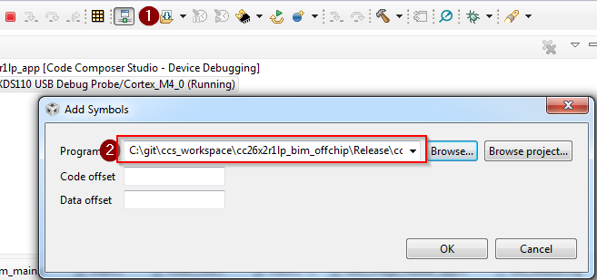
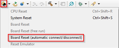
- Reset the device using the debugger. This will disconnect the target.
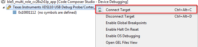
- Connect to the target:
- Set a breakpoint in
bim_main.c::Bim_checkImages()from the BIM project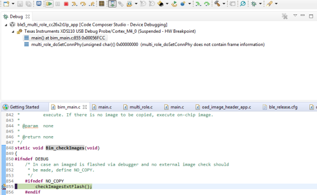
At this point you should be able to single step through the BIM code.
Select the following statements that are true about BIM.
Debugging Slow OAD Download Speeds
One of the major improvements of the enhanced OAD profile are its utilization of MTU exchange and scalability of over the air block sizes. There are two major factors that determine the speed of an OAD download:
- The connection interval
- The OAD block size
The connection interval is set by the master in the connection, but an update can be requested by the slave device. Ultimately, it is up to the master to set the connection parameters. You can read more about this in the BLE Connections SLA lab.
One way to force a slow OAD is to prevent BTool from sending a connection parameter update at the start of OAD. In this case, the OAD Target device will send the parameter update that will slow the connection interval. This is normally a good practice for power savings reasons, but if an OAD is occurring this can be detrimental to speed.
- Connect to the OAD Target device via BTool.
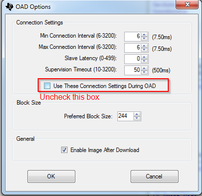
- Navigate to the Over the Air Download tab
- Select the options pane and disable the check box near
"Use These Connection Settings During OAD". This will prevent BTool from
sending a new connection parameter update at the beginning of an OAD.
- Start the OAD, observe slow speeds
- Cancel the OAD, re-check the box from step 3, and re-start the OAD.
- Repeat step 4
- After the parameter update is received, start the OAD via BTool. Observe that the speed will be much quicker.
Another contributing factor to the overall OAD throughput is the MTU size. The OAD block size is set by the OAD target device based on the MTU exchange. MTU exchanges are initiated by the GATT client device. There are three ways that the OAD session may potentially suffer from low throughput due to MTU size.
The OAD Target device is not built to support large MTU.
- This is controlled by the
MAX_PDU_SIZE. This define can range up to 255. - The formula for supported MTU based on
MAX_PDU_SIZEislocal supported MTU = MAX_PDU_SIZE - L2CAP_HDR_SIZE
- This is controlled by the
The OAD Distributor device does not support a large MTU, or the GATT client has not initiated an MTU exchange
- Just as locally the device must support large MTU, so must the peer, legacy or memory constrained peer devices may not support large MTU.
The OAD target is not reporting a negotiated MTU event to the OAD module.
- This is achieved by the the call to
OAD_setBlockSize()
- This is achieved by the the call to
The following steps will detail how to perform an OAD with smaller MTU size
- Open the BTool OAD Options window, and set "Preferred Block Size" to 24.
- Connect to the device and re-start the OAD.
- Observe that the total download time has greatly increased as the total blocks have increased to ~5570 (for a merged image).
What can an OAD Target device operating as a peripheral do to ensure high throughput and thus faster OAD speeds?
Task 4 – Bonus: Creating a Production Image
A production image is a single image that is made of all the images involved in an OAD system. In the case of off-chip OAD, the production image will consist of the app+stack merged image, and the BIM. Production images are desirable because they can be used to program devices in a test environment or production line using a single image. These images also must contain a valid image header.
Since the production image must contain a valid image header, the
_oad_merged.bin image output by the TI Image Tool
must be used.
This bin file contains the app+stack combined image. However, the app+stack
image cannot boot without a BIM included on the device, so for a production
image the app+stack image must be merged with the BIM image.
To combine the images, we will use the SRecord tool. The below steps assume that the FlashOnly configuration of the BIM is used, and the FlashROM configuration of multi_role is used. The steps can be easily modified or adapted to cover other configurations or sample applications. The CCS workspace location will be referred to as <CCS_WORKSPACE_LOC>
Download SRecord
Unzip the SRecord package into a location that will be referred to as <SREC_LOC>
Make sure your application and BIM have been built
Run the following command, you will need to replace <SREC_LOC> and <CCS_WORKSPACE_LOC> to match your environment. This will generate a production image titled
mutli_role_oad_production.hexin <SREC_LOC><SREC_LOC>/srec_cat.exe <CCS_WORKSPACE_LOC>/bim_oad_offchip_cc2640r2lp_app/FlashOnly/bim_oad_offchip_cc2640r2lp_app.hex -intel <CCS_WORKSPACE_LOC>/multi_role_cc2640r2lp_app/FlashROM_StackLibrary/multi_role_cc2640r2lp_app_FlashROM_StackLibrary_oad_merged.bin -bin -o mutli_role_oad_production.hex -intelUse Uniflash to flash the
mutli_role_oad_production.hexon the device, verify that the device is working and runs through a reset.
SRecord Examples
For more information and SRecord usage samples please see srec_examples
You have now created an OAD production image.
This work is licensed under a Creative Commons Attribution-NonCommercial-NoDerivatives 4.0 International License.