Introduction
This workshop demonstrates how to use the Boot Loaders in the SimpleLink™ MSP432E4 Software Development Kit (SDK). The Boot Loader database provided as part of the SDK can be used to develop custom Boot Loaders over the serial interfaces of UART, I2C, SSI or Ethernet to download application firmware to the MSP432E4 device.
At the end of this training, the audience should be able to:
- Configure and build the FLASH based boot loader on the MSP432E4 LaunchPad.
- Configure and build the application image on the MSP432E4 LaunchPad.
- Download and execute the FLASH based boot loader to the MSP432E4xx device on the MSP-EXP432E401Y LaunchPad.
- Download and execute the application image to the MSP432E4xx device on the MSP-EXP432E401Y LaunchPad.
- Call the FLASH boot loader from the application image to download a new application image to the MSP432E4.
- Understand the options in BSL Scripter to use the boot loader mode of the MSP432E4xx device.
Prerequisites
Software
- Code Composer Studio v7.3.0 or later.
- Must have SimpleLink MSP432E4 support
- Make sure that CCS is using the latest updates: Help → Check for Updates
- MSP432E4 SDK v1.55.00.21 or later.
- BSL Scripter v3.3.0 or later.
- MSP430 USB Firmware Upgrade Utility
- BSL Rocket Firmware MSP-BSL-ROCKET-FW
- Terminal emulator program such as TeraTerm
Hardware
- MSP432E4 LaunchPad (MSP-EXP432E401Y)
- 1x Micro-USB cable (included with LaunchPad)
- 1x Ethernet cable (when using the Ethernet Boot Loader)
- 1x Ethernet switch (when using the Ethernet Boot Loader)
- BSL Rocket
Boot Loader Overview
Boot Loader Concept
- Boot Loader is an efficient way of updating an application image on a MCU when it is already deployed in the field.
- A Boot Loader Update mechanism must be able to detect either a GPIO switch press or a special control packet over the communication interface to switch the device from application image execution to boot loader execution.
Boot Loader System Diagram
- PC Host: which runs the BSL scripter application, that reads the application image that has to be downloaded to the target device.
- Programmer: like the BSL rocket which must be used when downloading the new application image over UART, I2C or SSI.
- Target Device:
which runs the Boot Loader that can accept data packets over the selected interface either from the Programmer or the PC Host.
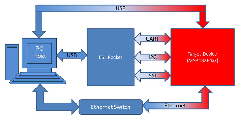
Acronyms:
I2C – Inter Integrated Circuit
SSI – Serial Synchronous Interface
UART – Universal Asynchronous Receiver Transmitter
USB – Universal Serial Bus
Running the Serial Boot Loader and Downloading an Application Image over Serial Interfaces (I2C, SSI and UART)
The following section will walk you through the steps needed to run the BSL Scripter to download the Boot Loader and Application Image using BSL Rocket (for I2C, SSI or UART) to the MSP-EXP432E401Y LaunchPad.
Task 1: Preparing the BSL Rocket
Download the BSL Rocket Firmware MSP-BSL-ROCKET-FW from TI website.
Extract the content of the zip package to your PC.
The firmware image for the BSL Scripter is kept in the sub-folder firmware and is name MSP-BSL-Rocket_3_2_0.txt.
Download and Install MSP430 USB Firmware Upgrade Example Application.
In the Start Menu on your PC, navigate to the installed application MSP430 USB Firmware Upgrade Example.
When the application launches, click on "Next" to proceed to the Licensing Agreement Window.
In the Licensing Agreement Window click on the Radio-Button to accept the Licensing agreement but do not click on "Next" as the BSL Rocket has to be enumerated in device update mode.
Connect the USB cable provided with the "BSL Rocket" to your PC.
Press the switch marked USB_BSL on the back of the BSL Rocket when connecting the USB cable to the BSL Rocket.
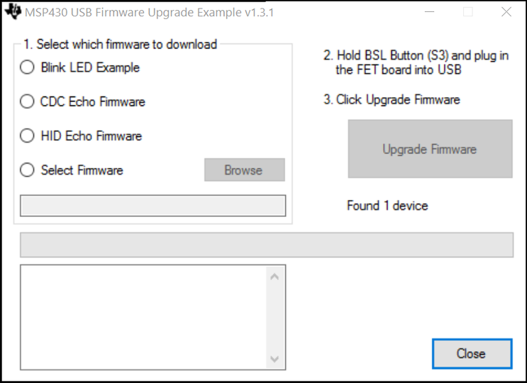
Then click on the "Next" button on the PC application. The MSP430 USB Firmware Upgrade Example v1.3.1 will launch and it would show the message "Found 1 device".
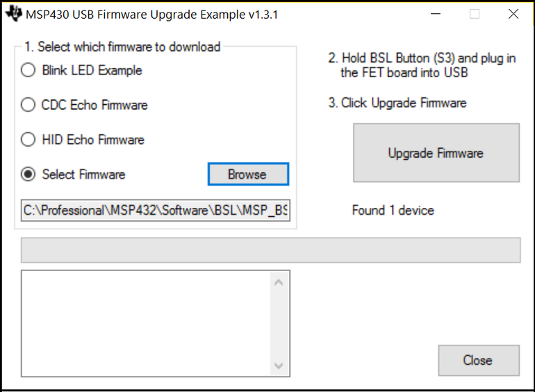
Now select the radio-button Select Firmware, click on Browse and select the BSL Rocket Firmware as shown in Step-3 earlier.
Now click on the "Upgrade Firmware" and the BSL Rocket Update should finish in 5-6 seconds.
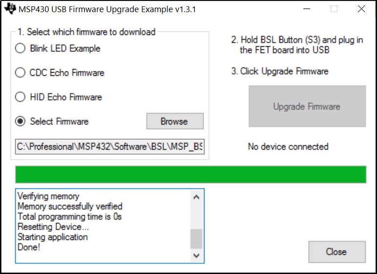
Now close the application and remember to power cycle the BSL Rocket to make sure the new firmware takes effect.
Task 2: Compiling the Boot Loader Images
The next task is to build the boot loader examples and generate the output files in TI txt format.
Start Code Composer Studio.
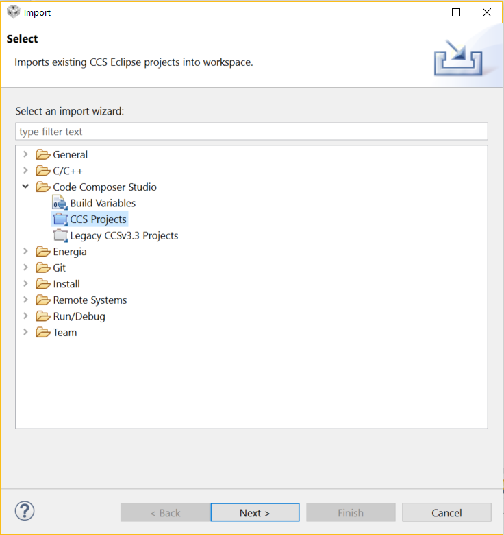
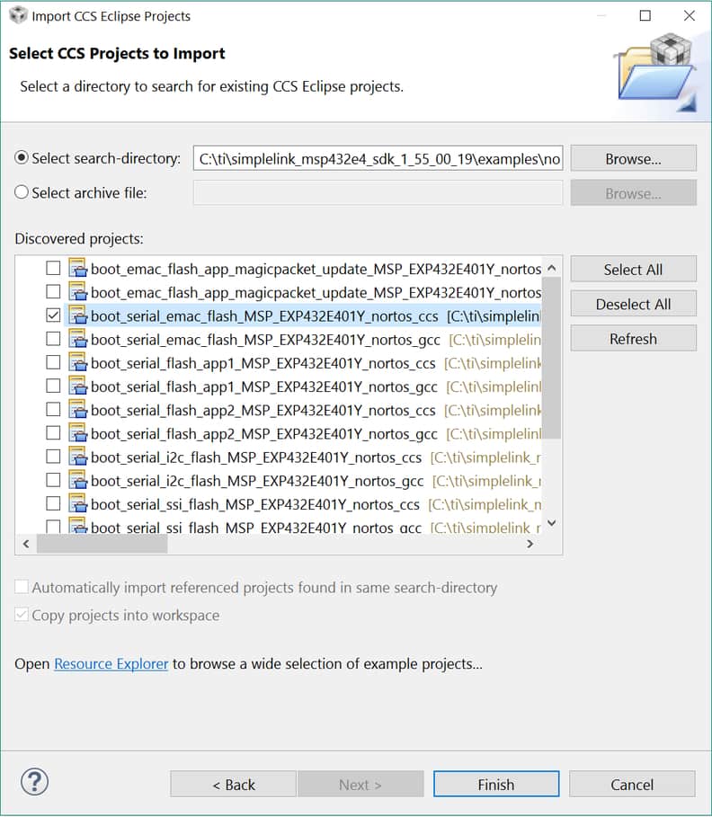
Click on File -> Import. In the Import pop-up box select Code Composer Studio -> CCS Projects from the menu and click on Next.
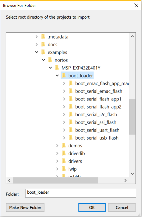
Select the radio-button Select search-directory and click on Browse. Now navigate to the examples for boot_loader.
For this build session we will take the example boot_serial_uart_flash_MSP_EXP432E401Y_nortos_ccs.
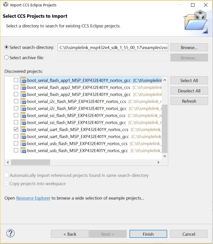
Click on Finish and the example project shall be imported into the Project Explorer of CCS.
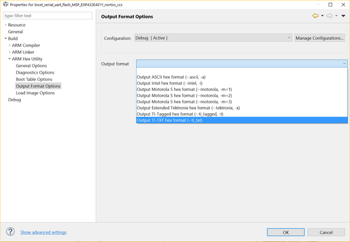
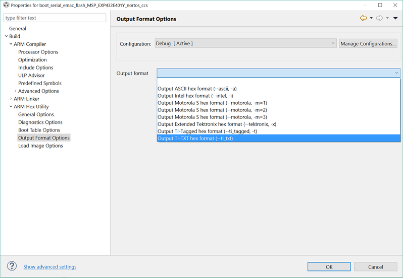
By default all projects in CCS generate the out file. Since we need TI txt format, we need to add the option for the Compiler and Linker to generate the file. This can be done by right-clicking the project and then clicking on the Properties in the drop down menu. In the pop-up menu, navigate to Build -> ARM Hex Utility. Select the check-box Enable ARM Hex Utility. Now navigate to Output Format Options and select the Output format as Output TI-TXT hex format (--ti_txt).
Now build the project. In the Project Explorer, expand the project and navigate to the Debug folder. The file boot_serial_uart_flash_MSP_EXP432E401Y_nortos_ccs.txt should be present. Copy the file to the place where the "BSL Scripter.exe" has been kept.
Task 3: Compiling the Application Images
The next task is to build the Application examples and generate the output files in TI txt format.
Since Code Composer Studio is already open repeat steps 2-3 of Task 2.
Import the examples boot_serial_flash_app1_MSP_EXP432E401Y_nortos_ccs and boot_serial_flash_app1_MSP_EXP432E401Y_nortos_ccs.
Repeat steps 5-6 of Task 2 to generate the TI txt format and build the projects.
In the Project Explorer, expand the projects and navigate to the Debug folder and copy the files boot_serial_flash_app1_MSP_EXP432E401Y_nortos_ccs.txt and boot_serial_flash_app2_MSP_EXP432E401Y_nortos_ccs.txt to the place where the "BSL Scripter.exe" has been kept.
Additional Task...
Import, Update and Compile all the other projects in CCS under boot_loader directory and generate the TI TXT file output.
Task 4: Preparing the LaunchPad
The MSP-EXP432E401Y LaunchPad comes with the placeholder for the BSL Rocket. The user has to solder a 5x2 100 mil header on the LaunchPad. Since several of the pins for different communication protocols are shared on the header, the MSP-EXP432E401Y Ethernet LaunchPad development kit enable support for all three protocols by using 0-ohm resistor bridges for each of the signals. To connect a specific protocol, the designated resistors should be populated with a 0-ohm resistor, and the others protocols should have their resistors removed (see Table below). When using I2C, pullup resistors should be populated to R13 and R14 if there are not I2C pullups on the external host. Typically the I2C pullup resistors should be 3.3k-ohms.
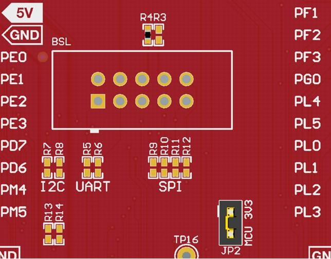
The table below shows the resistors that need to be populated with 0-ohms and left unpopulated for Serial Bootloader Interface using I2C
| Resistors populated with 0-ohms | Resistors left unpopulated |
|---|---|
| R7 | R5 |
| R8 | R6 |
| R9 | |
| R10 | |
| R11 | |
| R12 |
The table below shows the resistors that need to be populated with 0-ohms and left unpopulated for Serial Bootloader Interface using SSI
| Resistors populated with 0-ohms | Resistors left unpopulated |
|---|---|
| R9 | R5 |
| R10 | R6 |
| R11 | R7 |
| R12 | R8 |
The table below shows the resistors that need to be populated with 0-ohms and left unpopulated for Serial Bootloader Interface using UART
| Resistors populated with 0-ohms | Resistors left unpopulated |
|---|---|
| R5 | R7 |
| R6 | R8 |
| R9 | |
| R10 | |
| R11 | |
| R12 |
Note for this Lab.
Since we would be using the UART interface, we have to populate resistors R5 and R6 and make sure that resistors R7-R12 are not populated.
Task 5: Downloading the Boot Loader and Application Image
On a MSP-EXP432E401Y LaunchPad with fully erased Main Flash, remove the header jumpers marked RXD, TXD, RST, TMS, TCK, TDO and TDI from header J101.
Connect the BSL Rocket to the BSL header and connect the USB cable between the BSL Rocket and the PC. The RED LED on the LaunchPad must lit up to indicate that the power is applied.
Open the command prompt on the PC and change directory to where the BSL Scripter exe has been kept.
Create a new text file called script_uart_bl.txt and copy the following content to the file and save it.
COM Port Settings.
Since the COM port enumerated for the BSL Rocket may be different for each PC, please check in the Windows Device Manager for the COM Port the BSL Rocket is enumerated on. For this workshop COM7 has been used.
Script content for Boot Loader Download
Make sure that the TI TXT file for the flash boot loader is in the same directory as the script.
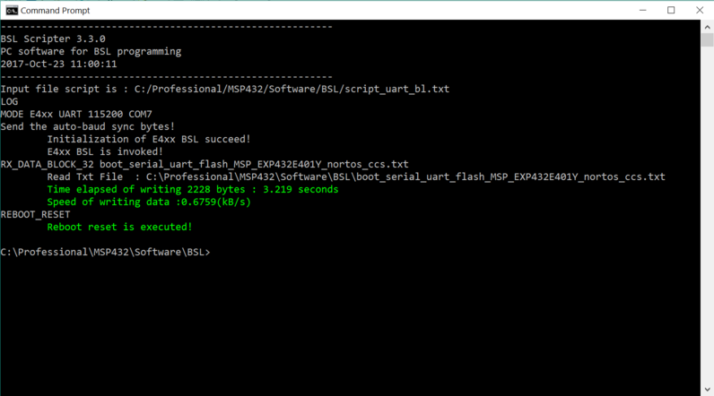
LOG
MODE E4xx UART 115200 COM7
RX_DATA_BLOCK_32 boot_serial_uart_flash_MSP_EXP432E401Y_nortos_ccs.txt
REBOOT_RESET
Run the BSL Scripter with the script_uart_bl.txt. The following screenshot demonstrates the execution of the BSL Scripter and a successful download of the flash based boot loader.
Create a new text file called script_uart_app1.txt and copy the following content to the file and save it.
COM Port Settings.
Since the COM port enumerated for the BSL Rocket may be different for each PC, please check in the Windows Device Manager for the COM Port the BSL Rocket is enumerated on. For this workshop COM7 has been used.
Script content for Application-1 Download
Make sure that the TI TXT file for the flash application is in the same directory as the script.
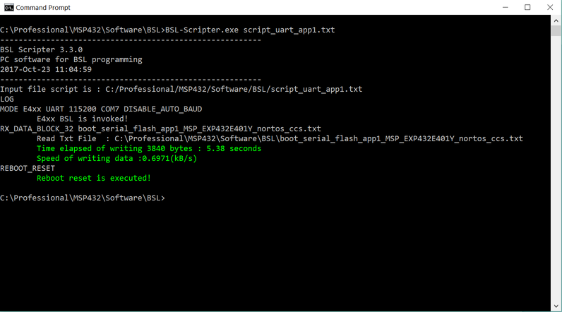
LOG
MODE E4xx UART 115200 COM7 DISABLE_AUTO_BAUD
RX_DATA_BLOCK_32 boot_serial_flash_app1_MSP_EXP432E401Y_nortos_ccs.txt
REBOOT_RESET
Run the BSL Scripter with the script_uart_app1.txt. The following screenshot demonstrates the execution of the BSL Scripter and a successful download of Application-1 using the flash based boot loader.
At this point the Application-1 has been downloaded to the device and the LED D1 should start blinking.
To see the boot loader download a new image press the User Switch USR_SW1 till the LED D1 stops blinking. Once the LED stops blinking it indicates to the user that the boot loader has been invoked by the application.
Create a new text file called script_uart_app2.txt and copy the following content to the file and save it.
COM Port Settings.
Since the COM port enumerated for the BSL Rocket may be different for each PC, please check in the Windows Device Manager for the COM Port the BSL Rocket is enumerated on. For this workshop COM7 has been used.
Script content for Application-2 Download
Make sure that the TI TXT file for the flash application is in the same directory as the script.
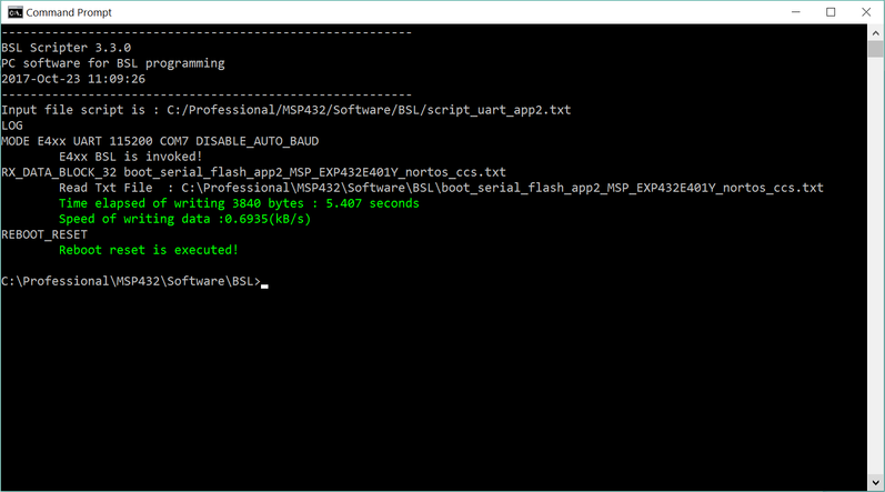
LOG
MODE E4xx UART 115200 COM7 DISABLE_AUTO_BAUD
RX_DATA_BLOCK_32 boot_serial_flash_app2_MSP_EXP432E401Y_nortos_ccs.txt
REBOOT_RESET
Run the BSL Scripter with the script_uart_app2.txt. The following screenshot demonstrates the execution of the BSL Scripter and a successful download of Application-2 using the flash based boot loader.
At this point the Application-2 has been donwloaded to the device and the LED D2 should start blinking.
Running the Ethernet Boot Loader and Downloading an Application Image over Ethernet
The following section will walk you through the steps needed to run the BSL Scripter to download the Boot Loader and Application Image using PC Host (for Ethernet) to the MSP-EXP432E401Y LaunchPad.
Task 1: Compiling the Boot Loader Image
The next task is to build the boot loader examples and generate the output files in TI txt format.
Start Code Composer Studio.
Click on File -> Import. In the Import pop-up box select Code Composer Studio -> CCS Projects from the menu and click on Next.
Select the radio-button Select search-directory and click on Browse. Now navigate to the examples for boot_loader.
For this build session we will take the example boot_serial_emac_flash_MSP_EXP432E401Y_nortos_ccs.
Click on Finish and the example project shall be imported into the Project Explorer of CCS.
By default all projects in CCS generate the out file. Since we need TI txt format, we need to add the option for the Compiler and Linker to generate the file. This can be done by right-clicking the project and then clicking on the Properties in the drop down menu. In the pop-up menu, navigate to Build -> ARM Hex Utility. Select the check-box Enable ARM Hex Utility. Now navigate to Output Format Options and select the Output format as Output TI-TXT hex format (--ti_txt).
Now build the project. In the Project Explorer, expand the project and navigate to the Debug folder. The file boot_serial_emac_flash_MSP_EXP432E401Y_nortos_ccs.txt should be present. Copy the file to the place where the "BSL Scripter.exe" has been kept.
Task 2: Compiling the Application Image
The next task is to build the Application examples and generate the output files in TI txt format.
Since Code Composer Studio is already open repeat steps 2-3 of Task 2.
Import the example boot_emac_flash_app_magicpacket_update_MSP_EXP432E401Y_nortos_ccs.
Repeat steps 5-6 of Task 2 to generate the TI txt format and build the projects.
In the Project Explorer, expand the projects and navigate to the Debug folder and copy the file boot_emac_flash_app_magicpacket_update_MSP_EXP432E401Y_nortos_ccs.txt to the place where the "BSL Scripter.exe" has been kept.
Task 3: Preparing the Setup
To run the Ethernet Boot Loader the following information is required.
The MAC Address of the MSP-EXP432E401Y LaunchPad: This is provided on a label on the back of the LaunchPad.
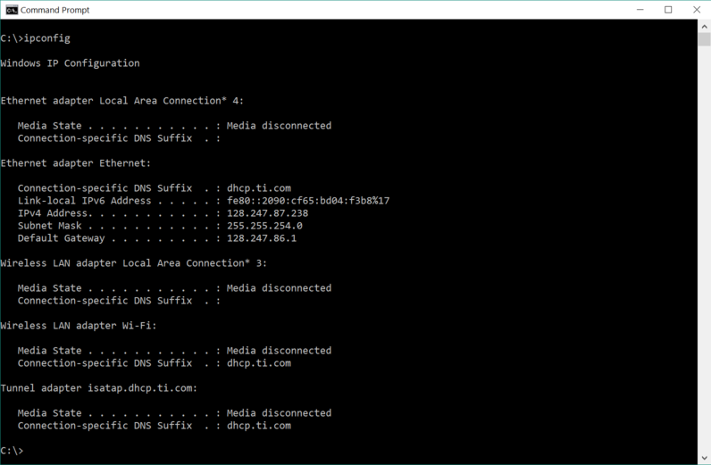
The Server IP Address: The Server IP address is the BOOTP server which is run by the BSL Scripter. The IP address is same as that of the PC Host which is running the BSL Scripter. To get the IP Address of the PC Host, open a command prompt and type in the command ipconfig. The following screenshot shows the IP Address of the PC Host on which we would run the BSL Scripter.
The Client IP Address: The Client IP address is the temporary IP address that the BOOTP server shall allocate to the MSP-EXP432E401Y LaunchPad for the TFTP data transfer. Typically this IP address should be one that has not been allocated on your network. One of the method to find a non-allocated IP address is to ping the IP address on your network. If a response timeout occurs, then you may use the non-allocated IP address for the Ethernet Boot Loader.
The next important task is to make sure that the setup is properly done for downloading applications over Ethernet. The following image shows how the setup must be connected.
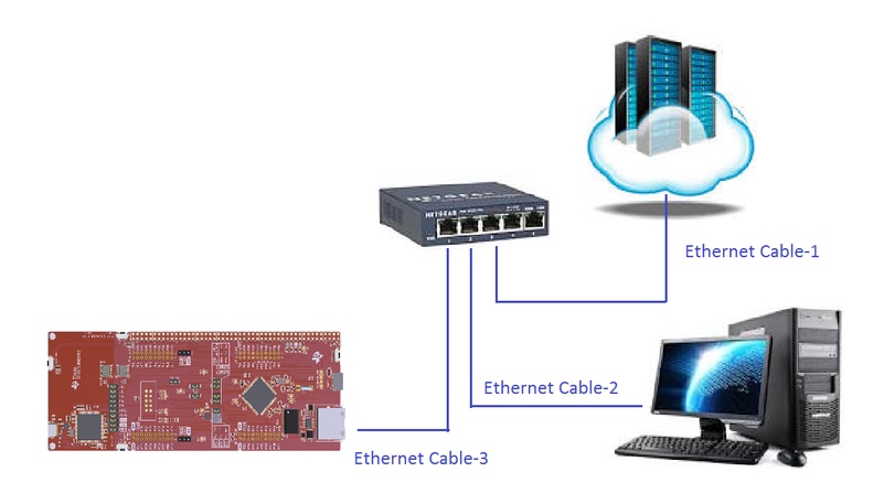
Ethernet Cable-1: To be connected between the 10/100 Mbps Switch and your network.
Ethernet Cable-2: To be connected between the 10/100 Mbps Switch and the PC Host.
Ethernet Cable-3: To be connected between the 10/100 Mbps Switch and the MSP-EXP432E401Y LaunchPad.
One such switch that may be used is NETGEAR GS110TP that has been used in this workshop. Any other suitable 10/100 Mbps Ethernet L2 switch may be used.
Task-4: Downloading the Boot Loader and Application Image
Power up a MSP-EXP432E401Y LaunchPad with fully erased Main Flash.
Connect the Ethernet Cables as per instructions provided in Task-3.
Open a Serial Console Application like TeraTerm on your PC and connect to the COM Port of the MSP-EXP432E401Y LaunchPad with 115200 bps 8-N-1 setting.
Open the command prompt on the PC and change directory to where the BSL Scripter exe has been kept.
Create a new text file called script_emac_bl.txt and copy the following content to the file and save it.
MAC Address Settings.
The MAC address is provided on a label on the back of the MSP-EXP432E401Y LaunchPad. For this workshop we are using the MAC Address 70:FF:76:1C:57:71.
Script content for Boot Loader Download
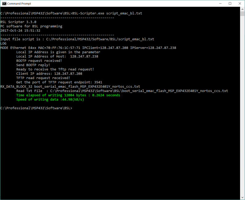
Make sure that the TI TXT file for the flash boot loader is in the same directory as the script.
LOG
MODE Ethernet E4xx MAC=70:FF:76:1C:57:71 IPClient=128.247.87.208 IPServer=128.247.87.238
RX_DATA_BLOCK_32 boot_serial_emac_flash_MSP_EXP432E401Y_nortos_ccs.txt
Run the BSL Scripter with the script_emac_bl.txt. The following screenshot demonstrates the execution of the BSL Scripter and a successful download of the flash based boot loader.
Create a new text file called script_emac_app.txt and copy the following content to the file and save it.
MAC Address Settings.
The MAC address is provided on a label on the back of the MSP-EXP432E401Y LaunchPad. For this workshop we are using the MAC Address 70:FF:76:1C:57:71.
Script content for Application-1 Download
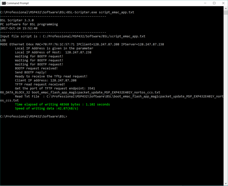
Make sure that the TI TXT file for the flash application is in the same directory as the script.
LOG
MODE Ethernet E4xx MAC=70:FF:76:1C:57:71 IPClient=128.247.87.208 IPServer=128.247.87.238
RX_DATA_BLOCK_32 boot_emac_flash_app_magicpacket_update_MSP_EXP432E401Y_nortos_ccs.txt
Press the Reset button on the MSP-EXP432E401Y LaunchPad and then run the BSL Scripter with the script_emac_app.txt. The following screenshot demonstrates the execution of the BSL Scripter and a successful download of the Application using the flash based boot loader.
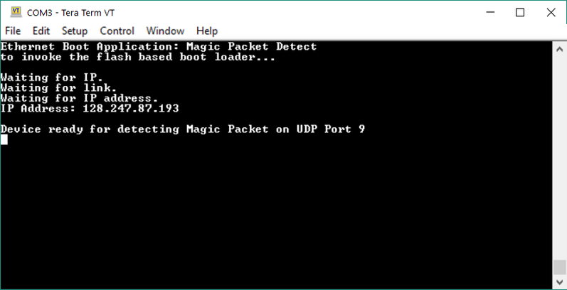
At this point the Application has been downloaded to the device and the LED D1 should start blinking. Also the COM port should show that the application executes and gets an IP address from your network DHCP server as shown in the snapshot below.
Further Reading
After experiencing the Boot Loader application with the MSP432E4x device, see the following resources for further assistance in development:
- Bootloader for MSP432E4xx SimpleLink™ Microcontrollers User's Guide: This guide contains information on how to build your own flash boot loader for different interfaces on the MSP432E4x MCU.
- Bootloader BSL Scripter User's Guide: This guide describes the BSL-Scripter.
- MSP-BSL Bootloader BSL Programmer for MSP430™ and SimpleLink™ MSP432™ MCUs: This guide describes the MSP-BSL Programmer.
Technical support
For any questions, please search on the TI SimpleLink MSP E2E Forum
This work is licensed under a Creative Commons Attribution-NonCommercial-NoDerivatives 4.0 International License.