Local Interconnect Network#
This module explains what LIN (Local Interconnect Network) means and how is that integrated in AM26x devices.
Introduction#
Local Interconnect Network (LIN) was introduced a low-cost serial communications protocol implemented mostly in automotive networks. It is typically used for mechatronic sub-nodes in automobiles (sensors, actuators), but is also well suited for industrial applications.
The LIN standard is based on the SCI (UART) serial data link format. The communication concept is single commander/multiple-responder with a message identification for multicast transmission between any network nodes.
The SCI module is a universal asynchronous receiver-transmitter (UART) that implements the standard non-return to zero format.
LIN vs CAN#
LIN |
CAN |
|---|---|
Low cost and low performance |
High cost and high performance |
Uses a single 12V wire |
Uses twisted shielded dual wires at 5V |
1 commander cluster |
Can have multible clusters |
Uses 6-bit identifiers |
Identifies with 11 to 29 bits |
Only operates at 20kbits/s |
Operates at 1Mbits/s (standard CAN) |
Features supported in AM26x devices#
SCI/LIN provides the following features:
Compatibility with LIN 1.3 protocols
Configurable baud rate up to 20 kpbs
Multibuffered receive and transmit units
Automatic commander header generation
Responder automatic synchronization
Automatic wake up support
Support for LIN 2.0 checksum
DMA capability to offload application
ID mask for message filtering
Automatic Bus Idle detection
For more information, checkout the Local Interconnect Network (LIN) chapter in the Device Technical Reference Manual.
LIN Integration in AM26x device#
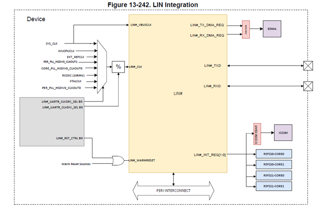
There are 5x LIN modules integrated in the device. LIN_CLK can be one of the following options -
LIN_CLK_SOURCE |
Source |
Default Frequency |
|---|---|---|
XTALCLK |
External XTAL |
25 MHz |
EXT_REFCLK |
External Reference Clock |
100 MHz |
SYSCLK |
PLL_CORE_CLK:HSDIV0_CLKOUT0 |
200 MHz |
DPLL_PER_HSDIV0_CLKOUT1 |
PLL_PER_CLK:HSDIV0_CLKOUT1 |
192 MHz |
DPLL_CORE_HSDIV0_CLKOUT0 |
PLL_CORE_CLK:HSDIV0_CLKOUT0 |
400 MHz |
RCCLK10M |
Internal 10MHz RC Oscillator |
10 MHz |
XTALCLK |
External XTAL |
25 MHz |
DPLL_PER_HSDIV0_CLKOUT0 |
PLL_PER_CLK:HSDIV0_CLKOUT0 |
160 MHz |
Note
In MCU+ SDK, input clock for LIN peripheral is configured as DPLL_PER_HSDIV0_CLKOUT1
Key Takeaway - LIN is not a full replacement of the CAN bus. But the LIN bus is a good alternative wherever low costs are essential and speed/bandwidth is not important. Typically, it is used within sub-systems that are not critical to vehicle performance or safety.
LIN Block Diagram#
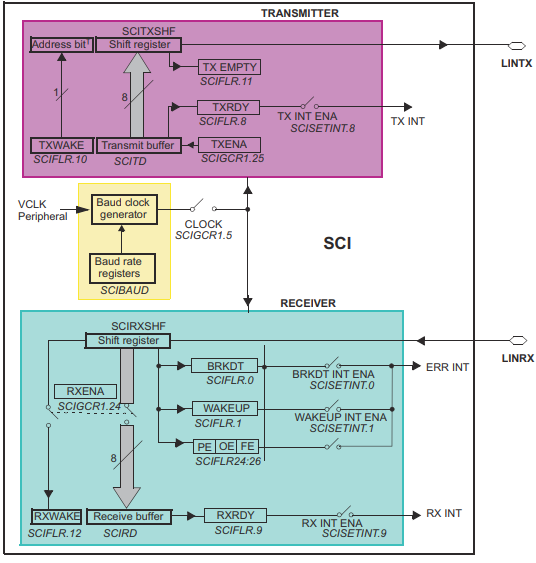
The SCI/LIN module is based on the standalone SCI with the addition of an error detector (parity calculator, checksum calculator, and bit monitor), a mask filter, a synchronizer, and a multibuffered receiver and transmitter. The SCI interface, the DMA control sub-blocks and the baud generator are modified as part of the hardware enhancements for LIN compatibility.
LIN Message Frame#
The LIN protocol defines a message frame format, shown below -
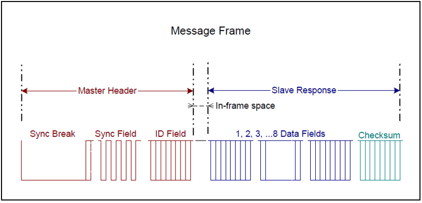
Each frame includes one commander header, one response, one in-frame response space, and inter-byte spaces. In-frame-response and inter-byte spaces may be 0. There is no arbitration in the definition of the LIN protocol; therefore, multiple responder nodes responding to a header might be detected as an error.
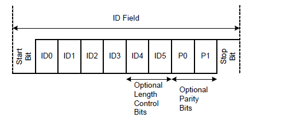
Message Header#
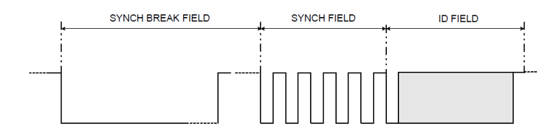
The header of a message is initiated by a commander and consists of 3 fields :
The synchronization break field signaling the beginning of a message.
This can be configures via
LIN_setSyncFieldsfunction.
The synchronization field conveying bit rate information of the LIN bus.
The identification field denoting the content of a message.
The Parity is calculated via
LIN_generateParityIDfunction.The ID with entire header is sent via
LIN_setIDBytefunction.
Response field#

There are two types of fields in a response - data and checksum.
Checksum can be configured into 2 types :
Enhanced Checksum
Classic Checksum
Both of them can be set via LIN_setChecksumType function.
LIN Baud Calculator#
The M field of the BRSR register modifies the integer prescaler P for fine tuning of the baud rate. The M value adds in increments of 1/16 of the P value.

In SDK, the LIN clock is at 192MHz i.e. DPLL_PER_HSDIV0_CLKOUT1. The P is configured as 624 and M as 0. So the final baud rate will be 19200 (maximum baud rate supported by LIN).
LIN Frame Timing#
A key property of the Local Interconnect Network (LIN) protocol is the use of schedule tables. Schedule tables make it possible to assure that the bus will never be overloaded.
More information about LIN with this following Application Note : LIN Protocol and Physical Layer Requirements.
LIN Transceivers and Physical Layer of LIN#
The Local Interconnect Network (LIN) physical layer is based on ISO 9141 (the K-line bus). It consists of the bidirectional bus line LIN which is connected to the transceiver of every bus node, and is connected via a termination resistor and a diode to the positive battery node, VBAT.
LIN Bus connections#
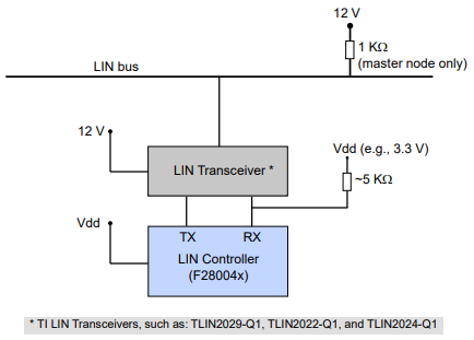
For more details on how the connectivity is done for AM263x Control Card Refer the following link
LIN Communication in AM26x devices#
LIN implements commander-responder principle for medium access control. All the messages are initiated by commander with at most one responder in the network. The LIN bus was designed to transport short control messages (2, 4, or 8 bytes).
Subscriber Mode Communication with AM26x device#
If the AM26x device is configured in commander mode, and let us assume the ID to be transferred is 0x22. The communication as per the agreement in the network is between the commander and the responder 1 to be configured as subscriber mode.
Note
Subscriber mode is a mode in which the responder is configured to receive the data which is sent by the commander. Red denotes the path of header and the Blue denotes the path of the data/response.
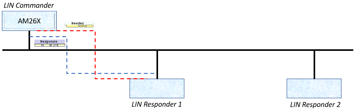
The AM26x device will be configured with txMask as 0x22.
Length of the data needs to be specified.
The data has to be populated in the Tx Buffers.
ID to be sent after the data is already populated.
Publisher Mode Communication with AM26x device#
If the AM26x device is configured in commander mode, and let us assume the ID to be transferred is 0x24. The communication as per the agreement in the network is between the commander and the responder 2 which is configured as a publisher.
Note
Publisher mode is a mode in which the responder is configured to send the data after receiving the header from the commander. Red denotes the path of header and the Blue denotes the path of the data/response.
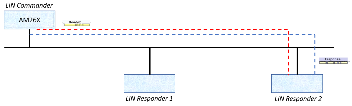
The AM26x device will be configured with rxMask as 0x24.
Length of the data needs to be specified.
ID to be sent.
The data will be populated in the Rx Buffers.
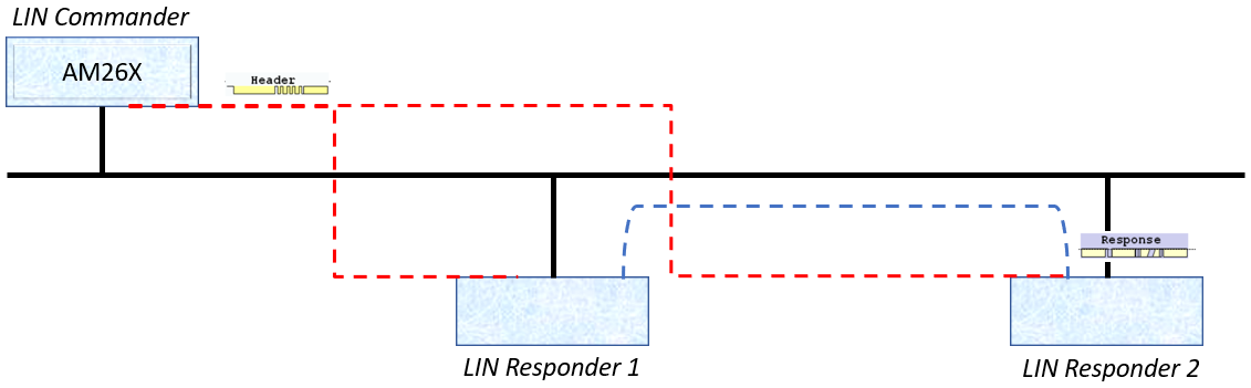
Responder to Responder mode of communication (Subscriber + Publisher mode)#
If the AM26x device is configured in commander mode, and let us assume the ID to be transferred is 0x27. The communication as per the agreement in the network is between the commander, the responder 1 as well as responder 2. The responder 1 is a subscriber whereas responder 2 is a publisher.
Note
Publisher mode is a mode in which the responder is configured to send the data after receiving the header from the commander. Subscriber mode is a mode in which the responder is configured to receive the data/response. Red denotes the path of header and the Blue denotes the path of the data/response.
The AM26x device will be configured with txMask as well as rxMask set as 0x00.
ID to be sent after the data is already populated.
LIN Examples#
Example Title |
Example Link |
|---|---|
Example for LIN Internal Loopback without Interrupts enabled |
|
Example for LIN Internal Loopback with Interrupts enabled |
|
Example for LIN in SCI Mode in Internal Loopback with Interrupts enabled |
|
Example for LIN in SCI Mode in Internal Loopback enabled with Tx and Rx via DMA enabled |
|
Example for LIN in LIN Mode without Loopback with External Communication |
|
Link to LIN Documentation in MCAL |