POSIX Project Zero#
Introduction#
POSIX is an IEEE industry API standard for OS compatibility. The SimpleLink™ software development kits (SDKs) has both TI-RTOS7 and FreeRTOS support. It also offers POSIX support on top of either of these RTOSes. This allows applications to be independent of the underlying RTOS.
This workshop provides a simple introduction to using POSIX with the SimpleLink SDK. You will use TI Resource Explorer, the SimpleLink SDK, and CCS Cloud to modify a project and run it on a SimpleLink LaunchPad™ Development Kit. The goal for this project is to familiarize you with some POSIX APIs and concepts typically used in multithreaded applications.
Here’s what we’ll learn:
How POSIX is supported with SimpleLink SDK.
The basics for creating POSIX threads and controlling their priorities.
The basics for creating and using POSIX message queues.
Prerequisites#
Recommended background reading#
SimpleLink Academy: TI Drivers Project Zero
SimpleLink Academy: RTOS Concepts
SimpleLink SDK Quick Start Guide: SDK Quick Start Guide
SimpleLink TI Drivers Runtime APIs: TI Drivers Runtime APIs
Software for development#
You can follow this tutorial using either of the following:
Desktop/offline tools if you have downloaded and installed the Code Composer Studio (CCS) IDE and the SimpleLink SDK for your LaunchPad: CCSTUDIO.
Web browser to access TI Resource Explorer and CCS Cloud.
Hardware requirements#
The TI Drivers are compatible with SimpleLink MCU devices. You can use this workshop with any CC26xx or CC13xx LaunchPad Development Kit.
For more information about compatable devices vist TI LaunchPad development kits
POSIX Support in SimpleLink SDK#
POSIX is not an RTOS. It resides on top of either TI-RTOS7 or FreeRTOS. As you can see with the following diagram, POSIX hides the underlying RTOS from the application. For more infomration in regards to the function of TI-RTOS7 and TI-POSIX refer to the below links.
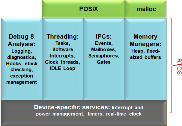
The SimpleLink SDK supports the following POSIX sets of APIs.
Pthread (includes mutexes, barriers, condition variables and read-write locks).
Semaphores
Clocks/Timers/sleep
Message Queue
Please note, not all POSIX APIs are supported in the SimpleLink SDK. For a more detailed list of the supported APIs and restrictions, please refer to the “Summary of functions supported in TI-POSIX” section of the “TI-POSIX User’s Guide” document in your SDK download, or vist TI-POSIX User’s Guide.
Setting up the example project#
We will begin with a simple example that uses the UART2 driver to echo back to the console. We’ll then extend that example to add an alarmThread. Once the alarmThread is integrated into the example, typing an ‘X’ on the UART console will cause a message to be sent to the alarmThread, which then toggles an LED. We’ll see how to add in several different POSIX APIs to add this capability.
Task 1: Importing “uart2echo” with TI Resource Explorer#
Note
If you are using CCS Cloud, you may be asked to download and install browser extensions. Chrome is the recommended browser for developing with CCS Cloud.
Warning
Before you start If you haven’t yet gone through the TI Drivers Project Zero workshop, we recommend that you do that first. We’ll move quickly through the steps introduced in that workshop here.
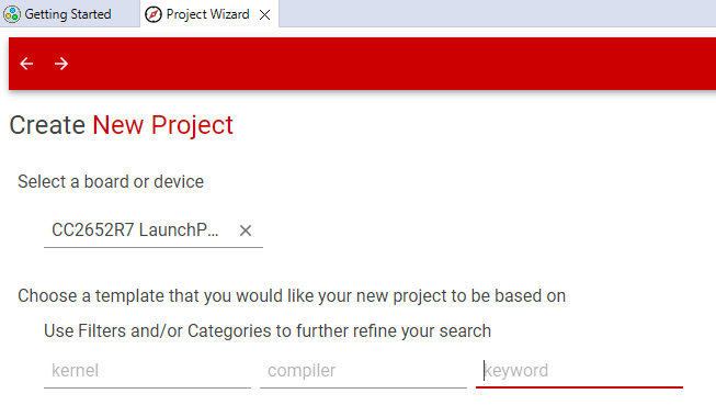
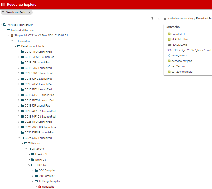
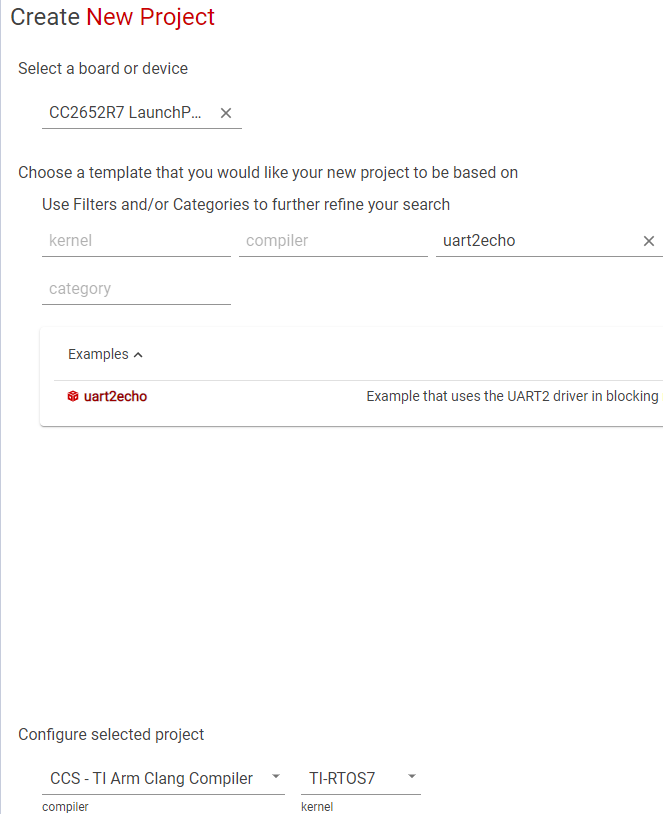
Open TI Resource Explorer (either in a web browser or within an installed version of CCS). In the keyword box, type “uart2echo” and press Enter.
You will see a list of products that include the simple “uart2echo” example, which uses the TI Driver for the UART to echo back to the console. Expand the tree for your device family as shown below until you see the “uart2echo” example. Notice that examples are provided for both the FreeRTOS and TI-RTOS7 kernels (for device families where FreeRTOS is supported) and for both the CCS compiler and the GCC compiler.
Under the SimpleLink product for your device family, expand Examples > Development Tools > [LaunchPad] > TI Drivers > uart2echo > TI-RTOS7 > CCS Compiler > uart2echo
Import the uart2echo example into CCS by clicking the Import to IDE icon when the project folder is highlighted.
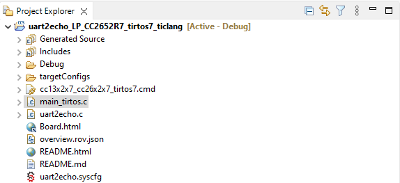
The example will be imported and shown in the project explorer on CCS.
Task 2. Exploring the uart2echo example#
As with all TI Driver examples, uart2echo is packaged with:
README.html, which you should read to learn how to run the example, you can also visit the web broswer version README.html.Board.html, which shows where hardware resources are located on your board and how they can be accessed in your software (for example, on-board LEDs and pushbuttons), vist the web browser version at Board.html.
The example contains a number of .c and .h files, but the files you will be modifying in this workshop are:
main_tirtos.cuart2echo.c
Note
For FreeRTOS users
If you chose to import a FreeRTOS version of the example, the file that contains main() is called main_freertos.c instead of main_tirtos.c; you will also need to add the FreeRTOS directory to your Linked Resoruces to build the FreeRTOS version of the example.
The main_tirtos.c file#
First let’s take a look at the main_tirtos.c source file – simply double-click the file to open it in CCS.
The #include statements and definitions prior to main() are as follows:
  #include <stdint.h>

  /* POSIX Header files */
  #include <pthread.h>

  /* RTOS header files */
  #include <ti/sysbios/BIOS.h>

  /* Driver configuration */
  #include <ti/drivers/Board.h>

  extern void *mainThread(void *arg0);

  /* Stack size in bytes */
  #define THREADSTACKSIZE    1024
<pthread.h>is included so that the POSIX APIs are available.<ti/sysbios/BIOS.h>is included so that the TI-RTOS7 Kernel is available. TI-RTOS7 uses a hierarchical module naming convention relative to<SDK_install_dir>\kernel\tirtos\packages, so theBIOS.hfile is located in<SDK_install_dir>\kernel\tirtos\packages\ti\sysbios.mainThread()is the function defined inuart2echo.c, which is run by a thread created in main().THREADSTACKSIZEspecifies the size of the stack (in bytes) that is allocated for the mainThread.
Note
For FreeRTOS users
The <FreeRTOS.h> and <task.h> headers would be included instead of <ti/sysbios/BIOS.h>.
Now, let’s look at the contents of the main() function. This is where we begin to see POSIX APIs. Details about using POSIX threads with the TI-RTOS7 Kernel and FreeRTOS through the SimpleLink SDK are provided in the “TI-POSIX User’s Guide” document in your SDK download. For more detail, see the official specification and documentation of the generic implementation.
  int main(void)
  {
  pthread_t           thread;
  pthread_attr_t      attrs;
  struct sched_param  priParam;
  int                 retc;

  /* Call driver init functions */
  Board_init();

  /* Initialize the attributes structure with default values */
  pthread_attr_init(&attrs);

  /* Set priority, detach state, and stack size attributes */
  priParam.sched_priority = 1;
  retc = pthread_attr_setschedparam(&attrs, &priParam);
  retc |= pthread_attr_setdetachstate(&attrs, PTHREAD_CREATE_DETACHED);
  retc |= pthread_attr_setstacksize(&attrs, THREADSTACKSIZE);
  if (retc != 0) {
      /* failed to set attributes */
      while (1) {}
  }

  retc = pthread_create(&thread, &attrs, mainThread, NULL);
  if (retc != 0) {
      /* pthread_create() failed */
      while (1) {}
  }

  BIOS_start();

  return (0);
  }
In general, the main() function does the following:
Board_init()initializes the board. For example, it initializes the Power Manager and verifies that pins can be accessed.The
main()function then sets attributes for and creates a POSIX thread. The process of creating a thread is described in more detail below.BIOS_start()runs the TI-RTOS7 Kernel. That is, it causes the kernel’s scheduler to take over, and threads that have been created run according to the rules of the scheduler. If this were a FreeRTOS version of the same example, thevTaskStartScheduler()function would be run instead.The
BIOS_start()function never returns, butreturn(0)is included for completeness.
See how the POSIX thread was created
The pthread_attr_init() function initializes the pthread_attr_t object pointed to by attrs. Its fields are set to their default values.
The priParam.sched_priority field is set to 1. This is the lowest thread priority.
The pthread_attr_setdetachstate() function sets the state of the thread to be created as PTHREAD_CREATE_DETACHED, because you won’t be calling pthread_detach() and pthread_join() to pause and resume execution of this thread.
The pthread_attr_setstacksize() function sets the size of the stack (in bytes) that will be allocated for the mainThread.
Once all these attributes have been set, the pthread_create() function creates the thread. The thread uses the attrs set of attributes and the mainThread will be the function run by the thread. If you wanted to pass information to the thread function, you could pass something other than NULL as the final function argument. The ID of a successfully created thread is stored in thread.
Note
Corresponding TI-RTOS7 Kernel code In TI-RTOS7 Kernel terms, this example creates a Task object, whose function runs at a higher priority than the Idle thread. If you were constructing this Task with TI-RTOS7 Kernel APIs instead of POSIX, the code could look like this:
  /* Construct BIOS Task */
  Task_Struct task0Struct;
  Char task0Stack[THREADSTACKSIZE];

  ...

  Task_Params taskParams;

  Task_Params_init(&taskParams);
  taskParams.priority = 1;
  taskParams.stackSize = THREADSTACKSIZE;
  taskParams.stack = &task0Stack;
  taskParams.instance->name = "echo";
  Task_construct(&task0Struct, (Task_FuncPtr)mainThread, &taskParams, NULL);
The above code also provides the stack to minimize memory allocation.
The uart2echo.c file#
Now let’s look at the uart2echo.c file, which contains the mainThread() function, which is run by the thread created in main().
The thread function performs the following actions before dropping into a loop where the UART is echoed continuously.
Initializes the GPIO driver.
Initializes the UART2 driver.
Turns on the board’s LED by writing to the GPIO driver.
Creates a UART object that will send characters to a serial session connected to a COM port (See
README.htmlfor more details).Opens the UART object.
Writes “Echoing characters:” to the UART object.
Once in the while loop, the function:
Reads a single character from the UART object (the serial session)
Writes a single character back to the UART object.
/*
 *  ======== mainThread ========
 */
void *mainThread(void *arg0)
{
    char input;
    const char echoPrompt[] = "Echoing characters:\r\n";
    UART2_Handle uart;
    UART2_Params uartParams;
    size_t bytesRead;
    size_t bytesWritten = 0;
    uint32_t status     = UART2_STATUS_SUCCESS;

    /* Call driver init functions */
    GPIO_init();

    /* Configure the LED pin */
    GPIO_setConfig(CONFIG_GPIO_LED_0, GPIO_CFG_OUT_STD | GPIO_CFG_OUT_LOW);

    /* Create a UART where the default read and write mode is BLOCKING */
    UART2_Params_init(&uartParams);
    uartParams.baudRate = 115200;

    uart = UART2_open(CONFIG_UART2_0, &uartParams);

    if (uart == NULL)
    {
        /* UART2_open() failed */
        while (1) {}
    }

    /* Turn on user LED to indicate successful initialization */
    GPIO_write(CONFIG_GPIO_LED_0, CONFIG_GPIO_LED_ON);

    UART2_write(uart, echoPrompt, sizeof(echoPrompt), &bytesWritten);

    /* Loop forever echoing */
    while (1)
    {
        bytesRead = 0;
        while (bytesRead == 0)
        {
            status = UART2_read(uart, &input, 1, &bytesRead);

            if (status != UART2_STATUS_SUCCESS)
            {
                /* UART2_read() failed */
                while (1) {}
            }
        }

        bytesWritten = 0;
        while (bytesWritten == 0)
        {
            status = UART2_write(uart, &input, 1, &bytesWritten);

            if (status != UART2_STATUS_SUCCESS)
            {
                /* UART2_write() failed */
                while (1) {}
            }
        }
    }
}
Task 3: Building and testing uart2echo#
Before we begin modifying the example, let’s test it to verify that it runs.
To build your project in CCS, simply click the hammer icon. This compiles your code and provides a .out file, which you can flash into your device. Alternatively, you can click the Debug icon, which compiles your code and flashes your hardware. It will also jump you into a debug session, where you can step through your code, set breakpoints and watch variables.
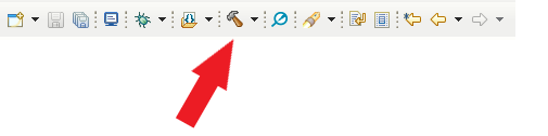
To program your LaunchPad, click the “Debug” button in CCS . This builds your project and flashes your hardware with the newly compiled image.
See the
README.htmlandBoard.htmlfiles in your project for instructions about running the uart2echo example.
Extending your code example#
Now we can extend the example to turn on an LED when you type an ‘X’ on the UART console.
To send an alarm message, we’ll use a POSIX message queue with a new POSIX thread called alarmThread. In response to a message on the message queue, this alarmThread will cause an LED on the board to toggle on and off as “X” is typed.
So, to summarize the changes we’ll need to make:
main()needs to open a POSIX message queue that will be used to send messages between threads.main()needs to create a POSIX thread to receive and respond to the messages that will be sent. We’ll set this to a higher priority so that the alarm will be serviced quickly. The thread to service the alarm will have a function calledalarmThread().mainThread()needs to check the input character received from theUART2_read(). If it is an ‘X’, it should send a message on the message queue. Otherwise, it should echo the character typed to the UART as usual.A new function called
alarmThread()needs to be created to service the alarm. We’ll put this in a separate file calledalarm.c.
Note
Communication between threads Other POSIX tools for synchronizing thread access to shared resources include mutexes, barriers, condition variables, read-write locks, semaphores, and timers.
For more readings, see the official specification and documentation of the generic implementation for insight into using POSIX threads with TI-RTOS7 Kernel.
Task 4: Opening a POSIX message queue#
POSIX message queues support communication between threads. To enable use of message queues and threads, the file needs to include the header file for POSIX message queues, which is mqueue.h. In addition, the GPIO driver needs to be initialized so that we can make sure the LED turns on to indicate mainThread is running, and toggles the LED to indicate when message queue receives a message.
We’ll add code to
main_tirtos.cto open the POSIX message queue. Open that file (ormain_freertos.c) for editing.Add the following statements to the list of #includes before
main():
  #include <mqueue.h>
  #include <ti/drivers/GPIO.h>
  #include "ti_drivers_config.h"
Some constants and a global variable are needed in order to use the message queue. Add these statements just before the beginning of
main():
  #define MSG_SIZE sizeof(int)
  #define MSG_NUM  4

  mqd_t mqdes;
The mqdes variable will receive the message queue descriptor used to access the message queue by the threads. Note: we have this as a global variable to make sure the memory stays persistent.
Add the following declaration to the declarations within
main(). ThemqAttrsstructure allows you to specify message queue flags, the maximum number of messages, and the message size for the message queue.
struct mq_attr mqAttrs;
Add the following code after the call to
Board_init():
  GPIO_init();

  GPIO_setConfig(CONFIG_GPIO_LED_0, GPIO_CFG_OUT_STD | GPIO_CFG_OUT_LOW);

  GPIO_write(CONFIG_GPIO_LED_0, CONFIG_GPIO_LED_OFF);

  mqAttrs.mq_maxmsg = MSG_NUM;
  mqAttrs.mq_msgsize = MSG_SIZE;
  mqAttrs.mq_flags = 0;
  mqdes = mq_open ("alarm", O_RDWR | O_CREAT,
                0664, &mqAttrs);
  if (mqdes == (mqd_t)-1) {
  /* mq_open() failed */
  while (1);
  }
This code performs the following:
Initializes the GPIO driver. Previously, this was done in
mainThread(), so we will need to remove it from there.Writes to the GPIO driver to turn off the board’s LED (just in case).
Sets values for the files in the
mqAttrsstructure that will be used when creating the message queue.Calls
mq_open()to create and open the message queue. The queue will be named “alarm”, created using the provided structure of typemq_attr(O_CREAT), and opened for both receiving and sending messages (O_RDWR). The octal value 0664 provides a required mode argument to the O_CREAT flag. (0664 indicates the user and group can read and write, while all others can only read.)Verifies that the message queue was created successfully. If not, it loops forever.
Note
Corresponding TI-RTOS7 Kernel code In TI-RTOS7 Kernel terms, the POSIX message queue is implemented using the Mailbox module.
Task 5: Creating a POSIX thread to handle the message#
Next, main() needs to create a POSIX thread to receive and respond to the messages that will be sent.
After the declaration of the
mainThread()external function, add the following declaration of thealarmThread()external function that will service the alarm.
extern void *alarmThread(void *arg0);
Add the following declaration to the declarations within
main(). The “alarm” variable will be used when creating the new thread.
pthread_t alarm;
Right before the statement that calls
BIOS_start(), add the following statements to create another POSIX thread. This thread will have a higher priority so that the alarm can be serviced ahead of echoing other characters that have been typed. A higher number indicates a higher priority. Note: we are using the fact that attrs has already been initializated, so we can just change the desired fields.
  /*
   *  Make the alarm thread a higher priority.
   */
  priParam.sched_priority = 2;
  pthread_attr_setschedparam(&attrs, &priParam);

  retc = pthread_create(&alarm, &attrs, alarmThread, (void *)&mqdes);
  if (retc != 0) {
  /* pthread_create() failed */
  while (1);
  }
Notice that the call to pthread_create() passes the message queue descriptor mqdes to the thread. This allows the thread to access the message queue.
The existing
mainThread()will also need to access the message queue. So, modify the first call topthread_create()to the following (change theNULLto(void *)&mqdes):
retc = pthread_create(&thread, &attrs, mainThread, (void *)&mqdes);
Save the
main_tirtos.cfile.Here is the full source for
main_tirtos.cif you want to confirm (or copy)
Full main_tirtos.c source
  /*
   *  ======== main_tirtos.c ========
   */
  #include <stdint.h>

  /* POSIX Header files */
  #include <pthread.h>
  #include <mqueue.h>

  /* Driver header files */
  #include <ti/drivers/GPIO.h>

  /* RTOS header files */
  #include <ti/sysbios/BIOS.h>

  /* Device initialization */
  #include <ti/drivers/Board.h>

  /* Driver configuration */
  #include "ti_drivers_config.h"

  extern void *mainThread(void *arg0);
  extern void *alarmThread(void *arg0);

  /* Stack size in bytes */
  #define THREADSTACKSIZE    1024

  #define MSG_SIZE sizeof(int)
  #define MSG_NUM  4

  mqd_t mqdes;

  /*
   *  ======== main ========
   */
  int main(void)
  {
  pthread_t           thread;
  pthread_t           alarm;
  pthread_attr_t      attrs;
  struct sched_param  priParam;
  int                 retc;
  struct mq_attr      mqAttrs;

  /* Call driver init functions */
  Board_init();
  GPIO_init();

  /* Configure the LED pin */
  GPIO_setConfig(CONFIG_GPIO_LED_0, GPIO_CFG_OUT_STD | GPIO_CFG_OUT_LOW);

  GPIO_write(CONFIG_GPIO_LED_0, CONFIG_GPIO_LED_OFF);

  mqAttrs.mq_maxmsg = MSG_NUM;
  mqAttrs.mq_msgsize = MSG_SIZE;
  mqAttrs.mq_flags = 0;
  mqdes = mq_open ("alarm", O_RDWR | O_CREAT,
                   0664, &mqAttrs);
  if (mqdes == (mqd_t)-1) {
      /* mq_open() failed */
      while (1);
  }

  /* Initialize the attributes structure with default values */
  pthread_attr_init(&attrs);

  /* Set priority, detach state, and stack size attributes */
  priParam.sched_priority = 1;
  retc = pthread_attr_setschedparam(&attrs, &priParam);
  retc |= pthread_attr_setdetachstate(&attrs, PTHREAD_CREATE_DETACHED);
  retc |= pthread_attr_setstacksize(&attrs, THREADSTACKSIZE);
  if (retc != 0) {
      /* failed to set attributes */
      while (1) {}
  }

  retc = pthread_create(&thread, &attrs, mainThread, (void *)&mqdes);
  if (retc != 0) {
      /* pthread_create() failed */
      while (1);
  }

  /*
   *  Make the alarm thread a higher priority.
   */
  priParam.sched_priority = 2;
  pthread_attr_setschedparam(&attrs, &priParam);

  retc = pthread_create(&alarm, &attrs, alarmThread, (void *)&mqdes);
  if (retc != 0) {
      /* pthread_create() failed */
      while (1) {}
  }

  BIOS_start();

  return (0);
  }
Task 6: Sending a POSIX message#
The mainThread() function needs to check the input character received from the UART2_read(). If it is an ‘X’, it should send a message on the message queue. Then it will echo the character typed to the UART as usual.
Open the
uart2echo.cfile from your CCS project.Since
mainThread()will need to callmq_send(), add the following statement to the list of #include files so that the POSIX module is available.
#include <mqueue.h>
In addition, add the following declarations to the declarations at the start of
mainThread().
  mqd_t      *mqdes = arg0;
  int         msg;
Recall that you moved the initialization and first call to the GPIO driver to
main(). Delete (or comment out) the following lines fromuart2echo.c.
  //GPIO_init();

  /* Configure the LED pin */
  //GPIO_setConfig(CONFIG_GPIO_LED_0, GPIO_CFG_OUT_STD | GPIO_CFG_OUT_LOW);

  /* Turn on user LED */
  //GPIO_write(CONFIG_GPIO_LED_0, CONFIG_GPIO_LED_ON);
Finally, add the following statements between the calls to
UART2_read()andUART2_write().
  if (input == 'X') {
  msg = 5;
  mq_send(*mqdes , (char *)&msg, sizeof(msg), 0);
  }
If an ‘X’ was typed, mq_send() sends the integer 5 as the message. This value is arbitrary and will not be used by the alarmThread(). However, you could further modify the example to take different actions based on the value of the message passed.
Save the
uart2echo.cfile.Here is the full source for
uart2echo.cif you want to confirm (or copy)
Full uart2echo.c source
/*
 *  ======== uart2echo.c ========
 */
#include <stdint.h>
#include <stddef.h>
#include <ti/sysbios/knl/Semaphore.h>
/* Driver Header files */
#include <ti/drivers/GPIO.h>
#include <ti/drivers/UART2.h>

/* Driver configuration */
#include "ti_drivers_config.h"
#include <mqueue.h>

/*
 *  ======== mainThread ========
 */
void *mainThread(void *arg0)
{
    char input;
    const char echoPrompt[] = "Echoing characters:\r\n";
    UART2_Handle uart;
    UART2_Params uartParams;
    size_t bytesRead;
    size_t bytesWritten = 0;
    uint32_t status     = UART2_STATUS_SUCCESS;
    mqd_t      *mqdes = arg0;
     int         msg;

    /* Call driver init functions */
    GPIO_init();

    /* Configure the LED pin */
    GPIO_setConfig(CONFIG_GPIO_LED_0, GPIO_CFG_OUT_STD | GPIO_CFG_OUT_LOW);

    /* Create a UART where the default read and write mode is BLOCKING */
    UART2_Params_init(&uartParams);
    uartParams.baudRate = 115200;

    uart = UART2_open(CONFIG_UART2_0, &uartParams);

    if (uart == NULL)
    {
        /* UART2_open() failed */
        while (1) {}
    }

    /* Turn on user LED to indicate successful initialization */
    GPIO_write(CONFIG_GPIO_LED_0, CONFIG_GPIO_LED_ON);

    UART2_write(uart, echoPrompt, sizeof(echoPrompt), &bytesWritten);
    GPIO_write(CONFIG_GPIO_LED_0, CONFIG_GPIO_LED_ON);
    /* Loop forever echoing */
    while (1)
    {
        bytesRead = 0;
            status = UART2_read(uart, &input, 1, &bytesRead);
       if (status != UART2_STATUS_SUCCESS)
        {
           //UART2_read() failed
           while (1) {}
        }

       if (input == 'X')
        {
           msg = 5;
            mq_send(*mqdes , (char *)&msg, sizeof(msg), 0);
        }

        bytesWritten = 0;
            status = UART2_write(uart, &input, 1, &bytesWritten);
       if (status != UART2_STATUS_SUCCESS)
        {
            //UART2_write() failed
            while (1) {}
        }

    }
}
Task 7: Creating a thread function to receive the POSIX message#
Now we’ll create the function to be run by the alarm thread. This function can be placed in a new file called alarm.c.
In CCS, choose File > New > Source File. For ‘Template’ choose None. Name the file
alarm.c.Paste the following code into the new file, and save the file in your CCS project.
  /*
   *  ======== alarm.c ========
   */

  #include <pthread.h>
  #include <mqueue.h>

  /* Driver Header files */
  #include <ti/drivers/GPIO.h>

  /* Driver configuration */
  #include "ti_drivers_config.h"

  /*
   *  ======== alarmThread ========
   */
  void *alarmThread(void *arg0)
  {
  mqd_t *mqdes = arg0;
  int msg;

  while (mq_receive(*mqdes, (char *)&msg, sizeof(msg), NULL) != -1) {
      /* Turn off and on LED when "X" is typed */
      GPIO_toggle(CONFIG_GPIO_LED_0);
  }

  return(0);
  }
The call to mq_receive() gets the message from the queue. If the message is received successfully, it calls GPIO_toggle() to turn off and on the board’s LED.
Task 8: Run the modified program#
Build and run the program you have modified. In the console, type some characters other than ‘X’ and then type ‘X’. Watch the LED on the board.
If you encounter problems, debug the code as necessary and compare your code to the listings above.
Quizzes#
Let’s see if you picked up some key points!
Great! Now what?#
You can extend the modified example in several ways. For example, you might want to pass a different message value to turn off the LED. Or, you could add a POSIX timer to turn off the LED after several seconds.
Remember that details about using POSIX threads with the TI-RTOS7 Kernel and FreeRTOS through the SimpleLink SDK are provided in the “TI-POSIX User’s Guide” document in your SDK download. For more detail, see the official specification and documentation of the generic implementation.
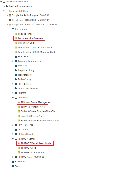
Also the TI Resource Explorer provides extensive documentation for TI Drivers, the TI-RTOS7 Kernel, TI-POSIX, and more. Documentation that may be especially helpful after you have completed this workshop is highlighted below.
Refer to TI-RTOS7 Kernel User’s Guide
Refer to TI-POSIX User’s Guide