Bluetooth Low Energy Enhanced Over the Air Download (OAD) Fundamentals#
Introduction#
This module covers the basics of the Over the Air Download (OAD) feature of the TI BLE5-Stack. The estimated time to complete this lab is 3 hours. It is assumed that the reader has a basic knowledge of embedded C tool chains and general C programming concepts. This lab is intended as a starting point for users who want to get familiar with OAD concepts and running a basic update demo.
OAD refers to the ability for an image to download a new executable image, over the air using the BLE5 protocol stack. A number of software components are involved in this process and TI uses OAD to refer to all of them as a software system.
This module does not cover updates via UART or SPI. For more information on wired update options, see the Serial Bootloader Interface application report.
This lab will cover an overview of a typical BLE5-Stack image and examine the high level anatomy of an OAD image. The first task will be to setup the environment to enable OAD. The next task will be running the out of the box demo for OAD using BTool, highlighting critical concepts along the way. The lab will conclude by reverting the newly downloaded image to a factory image.
This guide will split some tasks between on-chip and off-chip OAD. These section will look like below boxes. Please select the desired application by clicking on one of the tabs.
This content will be related to on-chip OAD applications
This content will be related to off-chip OAD applications
Warning
Do not mix On-Chip images with an Off-Chip setup and vice versa as this will lead to a failing boot up.
Prerequisites#
Hardware#
For this lab, you need two Bluetooth-enabled development boards. Supported devices are:
These devices are interchangeable in the lab.
Software for desktop development#
SIMPLELINK-LOWPOWER-F2-SDK Software Development Kit (SDK)
Code Composer Studio CCS Eclipse / CCS Theia / CCS Cloud or IAR
See Dependencies section of SDK release notes for required version.
Recommended reading#
SimpleLink Academy: Bluetooth Low Energy Fundamentals
SimpleLink Academy: Making a Custom Profile
Note
It is recommended to review the OAD Chapter of the BLE5-Stack User’s Guide before starting this lab.
Getting started – Desktop#
The following installation steps can be started in the background while reading the next chapter Anatomy of an OAD.
Install the Software#
Import Software Projects#
The following software projects will be used in this lab. They can be imported and compiled now.
Simple Peripheral OAD On-Chip
The project will use the simple_peripheral_oad_onchip project that
supports OAD. It is found in the ble5stack examples folder:
<SDK_INSTALL_DIR>\examples\rtos\<BOARD_NAME>\ble5stack\simple_peripheral_oad_onchip\tirtos7
Persistent App
The project persistent_app is required for on-chip OAD as well. It is found
in the ble5stack examples folder:
<SDK_INSTALL_DIR>\examples\rtos\<BOARD_NAME>\ble5stack\persistent_app\tirtos7
Boot Image Loader (BIM)
For this lab, the project bim_onchip is optional.
There is a pre-compiled binary available within the examples folder:
<SDK_INSTALL_DIR>\examples\nortos\<BOARD_NAME>\bim\hexfiles\bim_onchip
For reference, the full project is available in the bim examples folder:
<SDK_INSTALL_DIR>\examples\nortos\<BOARD_NAME>\bim\bim_onchip
Simple Peripheral OAD Off-Chip
The project will use the simple_peripheral_oad_offchip project that
supports OAD. It is found in the ble5stack examples folder:
<SDK_INSTALL_DIR>\examples\rtos\<BOARD_NAME>\ble5stack\simple_peripheral_oad_offchip\tirtos7
Boot Image Loader (BIM)
For this lab, the project bim_offchip is optional.
There is a pre-compiled binary available within the examples folder:
<SDK_INSTALL_DIR>\examples\nortos\<BOARD_NAME>\bim\hexfiles\bim_offchip
For reference, the full project is available in the bim examples folder:
<SDK_INSTALL_DIR>\examples\nortos\<BOARD_NAME>\bim\bim_offchip
As detailed in the introduction, the following tasks will cover some of the primary topics related to OAD using the BLE5-Stack.
Anatomy of an OAD#
This section seeks to explain the various components involved in an OAD image from a high level. Each software component will be treated as a building block that is added to a vanilla (Unmodified BLE5-Stack application without OAD such as simple_peripheral) BLE5-Stack image to eventually build an OAD image.
Default Non OAD Image#
We will begin with the template for a standard BLE5-stack image that does not have OAD enabled.
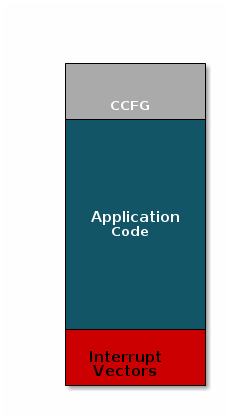
Image without OAD#
There are three main components of this image:
The instructions/constants that implement the compiled form of the program (application code)
The reset vectors in the ARM Cortex M format: ARM Cortex M4F Vector Table
The CCFG, which contains chip configuration parameters, see the Technical Reference Manual
These three components are required for any image that is to run on the CC26x2R or CC13x2R. The goal of OAD is to get an executable image of this form on the device via an over the air update, no JTAG or wires required.
However, in order to achieve the goal of making the image pictured above upgradeable over the air, a few software components must be set in place.
Image Fragmentation/ Image Header#
Even with the largest payload size supported by the Bluetooth Low Energy Specification, an entire CC26xx/CC13xx image cannot be sent in an single packet. This is for a number of reasons including:
TX time
Lost packet penalty
Preventing other packets from being sent.
Therefore, the image to be sent over the air must be fragmented into a size that will fit into Bluetooth LE GATT payloads.
The figure below pictures fragmentation of the stock image into GATT payloads.
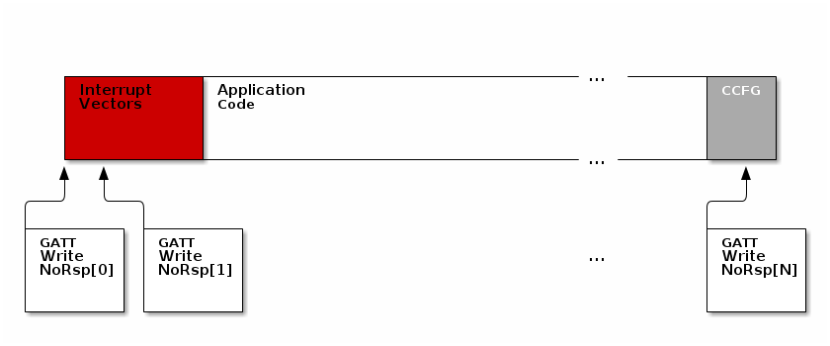
Image fragmentation#
As seen in the figure above, it will take many GATT packets to send a complete image over the air using the Bluetooth LE protocol. Each of these packets containing OAD image information is referred to as an OAD Block.
However, there is no way for the receiving device to know information about the incoming image. This problem is solved by using the OAD Image Header. The OAD Image Header contains metadata describing the image and is used by the application and BIM to determine the suitability of an image for downloading or loading. Other benefits of the OAD Image Header are:
Image metadata is bundled as part of the image
A running image can query knowledge about itself by reading the header
Bootloader software can read the header to determine which image(s) are present and active
Information about the incoming image is available to the target early in the OAD process.
Now, that we are sold on the benefits of an image header in an OAD system, here is an updated drawing of the stock image with an image header added.
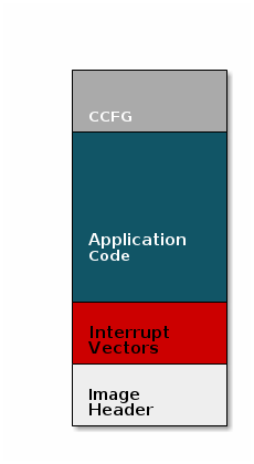
Image with Header#
Warning
Comparison: Image with and without header
When comparing images with a header and images without the header one must keep in
mind that the header itself takes up space.
The space available to the code section of the image is shrunk to accommodate
the header, and the reset vectors are pushed back to accommodate the header.
These changes are specified in the linker script (shrinking app space) and the
RTOS .cfg file (relocating reset vectors).
Boot Image Manager (BIM)#
A running image cannot update itself. This means that incoming OAD image must be stored in a temporary location while it is being received. This temporarily location can be a reserved location in internal flash outside of the executable area covered in the first image. Alternatively, the temporary location can be in an external flash chip.
After the download is complete, some code must determine if the new image is valid, and if current image should be overwritten, and finally execute the new image.
This piece of code is referred to as the Boot Image Manger (BIM) in the TI OAD solution.
BIM is intended to permanently remain on the device, meaning it persists through many OADs and cannot be updated.
BIM will run every time the device boots and determine if a new image should be loaded and run (based on image header).
Furthermore, the BIM and CCFG structure are tied together, because both are required for a successful device boot.
The CCFG is needed by the boot ROM and startup firmware for device trim and to
determine where program execution is to start from. By default the boot ROM will
jump to address 0x00000000 and look for a vector table, but this region is
now occupied by the image header. A custom CCFG must be used to instruct the
device to jump directly to the BIM.
From there the BIM will perform device trim based on the CCFG settings, and determine and load the optimal image based on the OAD image header.
The BIM code will require more reserved space in our system. See below for the memory map after a BIM has been added to the last image.
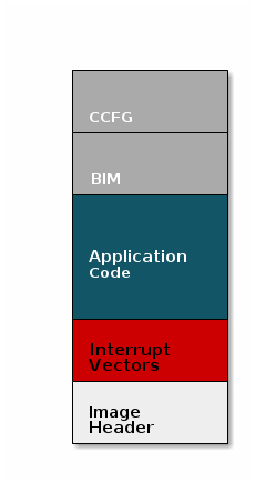
Image with Header and BIM#
Warning
The BIM is responsible for linking and defining the CCFG structure, instead of the application as in the non OAD case. This ensures that the device always will always execute the BIM after boot.
OAD Memory Layout#
The final memory structure depends on the type of OAD in use.
This section will describe the method for placing images in internal flash when using on-chip OAD.
Requirements and Constraints for On-chip OAD
In order to perform an On-chip OAD the target system must have:
The user application must be sufficiently small in order to fit into the flash layout system described below
User app functionality is lost while performing OAD (Persistent app is running)
Only one user application image may be stored in flash at any time.
Internal Flash Memory Layout
The internal flash of the device contains the active user application, the user application’s stack, the persistent application, the persistent application’s stack, and the BIM. Each application’s role is defined below.
As we have assumed the stack-library approach, the stack images referenced below are a part of each application image (i.e. the user and persistent apps have their own dedicated stack).
BIM
Search for the proper image in FLASH
Copy new user image
Ensure validity and optionally security of image before running
Persistent Application
Providing lightweight application that implements the OAD profile
Stack
BLE5-Stack protocol implementation
User Application
User defined application code
Must implement OAD reset service
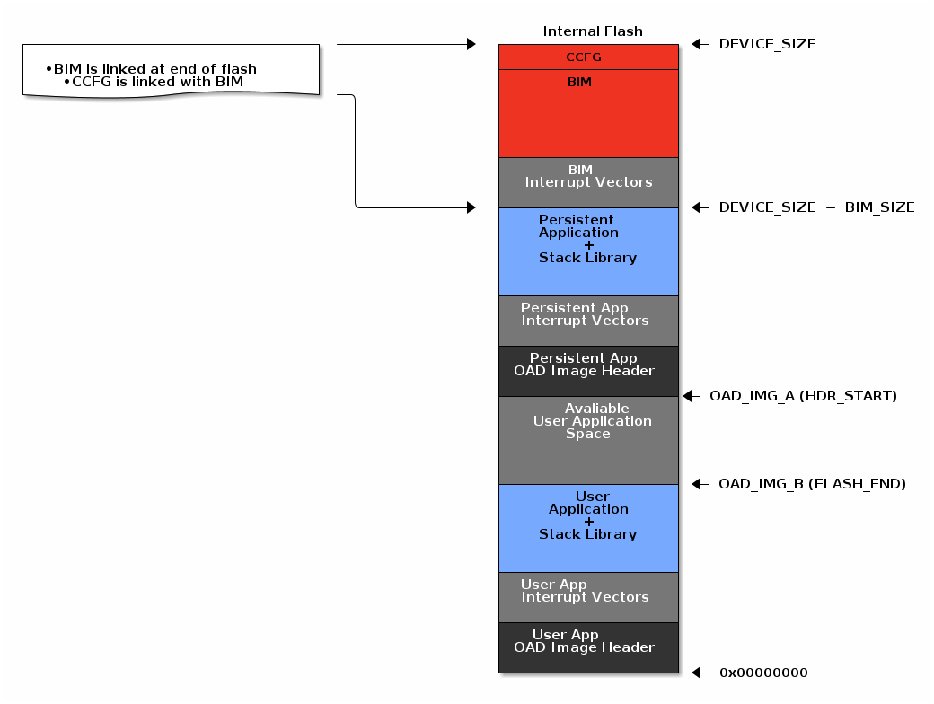
On-Chip OAD Image#
The user application (referred to as OAD_IMG_B) pictured above is responsible
for the following:
Implementing the protocol stack definition of the OAD reset service
Implementing customer defined behavior
The persistent application (referred to as OAD_IMG_A) pictured above is
responsible for the following:
Implementing the protocol stack definition of the OAD service This image is permanently resident on the device
The location of the persistent application varies depending on the flash size
available for the selected device variant. This is done to maximize the user’s
application space. Refer to the linker cmd file define IMG_A_FLASH_START to
further determine where precisely the persistent application is located.
This section will describe the method for placing images in internal and external flash when using off-chip OAD.
Requirements and Constraints for Off-chip OAD
Internal flash refers to the flash memory inside the CC13xx or CC26xx and external flash refers to an external SPI flash memory connected to the CC13xx or CC26xx via SPI.
In order to perform an Off-chip OAD the target system must have:
An off-chip flash storage as large as the application size + one external flash page to store the external flash image header. (default example will use 1MB of external flash)
A serial connection (SPI) is used to communicate with the off-chip flash component.
Free GPIO pins to interface to the external memory (i.e. 4 wires for SPI)
Enough free code space to reserve the entire contents of the last 1-2 flash page(s) for BIM
The following software limitations exist on the external flash:
The maximum number of simultaneously stored OAD images is 256.
The OAD images’ headers shall be stored in the first 1 MBytes of the external flash addressable space.
The total size of the stored images should not exceed 4 GBytes.
Note
Off-chip OAD using the BLE5-Stack has only be tested using a 1 MBytes external flash. The out-of-the-box software do not allow larger external flash size.
Internal Flash Memory Layout
The internal flash of the device contains the active user application and the BIM. Off-chip OAD maximizes the available flash space to the user application because of its ability to store the incoming image in external flash during the download process.
Note
When using security, the BIM may use a second page depending on the page size of the device. Consult the BIM’s linker file for more information.
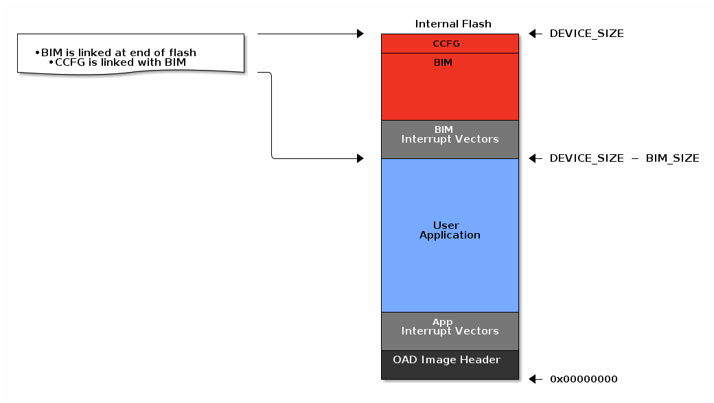
Off-Chip OAD Image Internal#
The user application pictured above is responsible for the following:
Implementing the protocol stack specific implementation of the OAD transport
Finding a suitable location in external flash for the image and storing its image header in the table.
External Flash Memory Layout
The off-chip flash memory on the CC13xx or CC26xx LaunchPad contains the image
header vector table and the user applications. The memory map layout of the
external flash part is defined in ext_flash_layout.h. The amount of space
reserved for each application is dynamically sized by the user application’s
implementation of the OAD protocol. The size of the image in external flash can
be determined once the image header vector is sent over the air.
The application will round up as necessary according to the equation below:

Off-Chip OAD Image External Formula#
The memory partition of the application for Off-chip OAD is depicted in below.
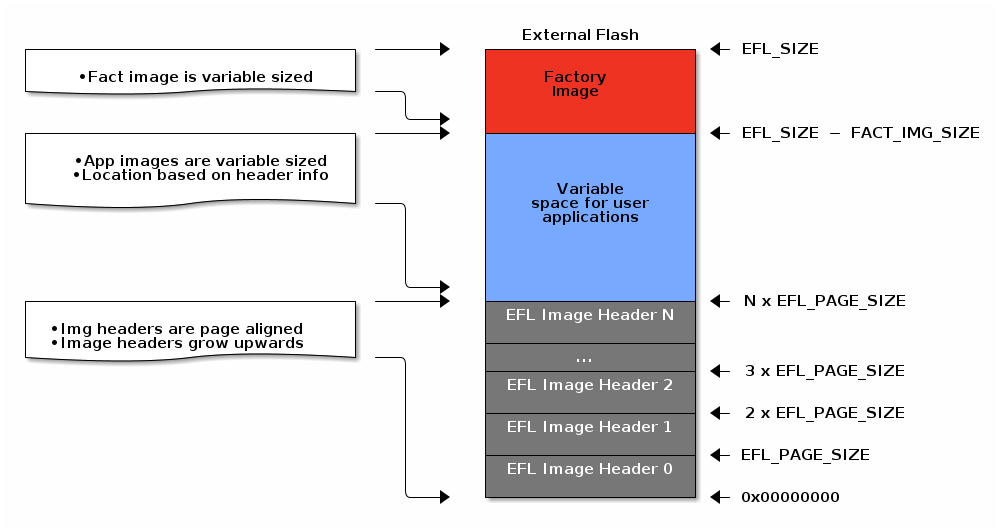
Off-Chip OAD Image External#
The size of the image header table is scalable and can be changed in the user application implementation of the OAD protocol.
The CC2640R2 SDK applications take a simplistic approach to external flash layout, partitioning the variable space in external flash into two sectors
Sector 0: used for all app images and is 128kB (matching device size for CC2640R2)
Sector 1: used for app+stack and other image types, also 128kB
The max number of metadata is capped at 4.
Other definitions can be found in ext_flash_layout.h.
Each entry to the image header table contains a pointer to its associated image location in external flash as shown below.
Warning
The convention is that image header sector 0 is reserved for the Factory Image. This region should be reserved for known good images as the BIM will revert to the factory image if there are no acceptable images in internal or external flash (user section).
OAD Protocol/ Bluetooth LE Profile#
Currently we have covered all the necessary building blocks for updating an image local to the target device. The only missing piece is a vehicle for sending the OAD blocks over the air and storing them on the target device.
This functionality is implemented by the BLE5-Stack OAD profile. As covered in the Custom Profile lab, the GATT profile is the vehicle for sending data over Bluetooth LE.
At a high level, the BLE5-Stack OAD profile is responsible for receiving the following:
Determining if the candidate image should be accepted for download
Receiving and unpacking image blocks and storing them
Writing the received blocks to non volatile storage
Verifying the received image post download
The BLE5-Stack OAD profile is implemented in the oad.c file and its associated
flash wrappers. Later, the module will cover the steps required to add the
BLE5-Stack OAD profile to a project.
Task 1 – Setting up the OAD Environment#
The OAD environment requires a two-step setup:
Flash the OAD Distributor with
host_testand connecting it withBTool.Flash the OAD Target with the BIM image and the application image. This example will use the
simple_peripheral_oad_offchipproject. For On-Chip OAD projects, thepersistent appwill also need to be flashed onto the OAD Target.Off-Chip OAD only: Create Factory Image. We will revert to this image in Task 3.
OAD Distributor Setup#
The OAD Distributor is the device responsible for fragmenting an OAD enabled image in to chunks of OAD blocks and sending each block over the to the OAD Target device as they are requested.
In the case of Bluetooth LE, the OAD Distributor is a combination of BTool
running on the PC connected to host_test running on a CC13xx or CC26xx
LaunchPad. host_test is a BLE5-Stack enabled network processor application.
BTool is a PC tool that is capable of interfacing to host_test and performing
various Bluetooth LE operations through HCI functions in addition to OAD. For
more information, refer to the host_test README file or the BTool User’s
Guide.
Flashing the host_test Image#
See below for the steps to setup the host_test image on a CC13xx or CC26xx LaunchPad.
Navigate to
hexfilesfolder within the BLE5-Stack and select the filehost_test_app.hex<SDK_INSTALL_DIR>\examples\rtos\<BOARD_NAME>\ble5stack\hexfiles\host_test_app.hexFlash the above hexfile using UNIFLASH. See image below:
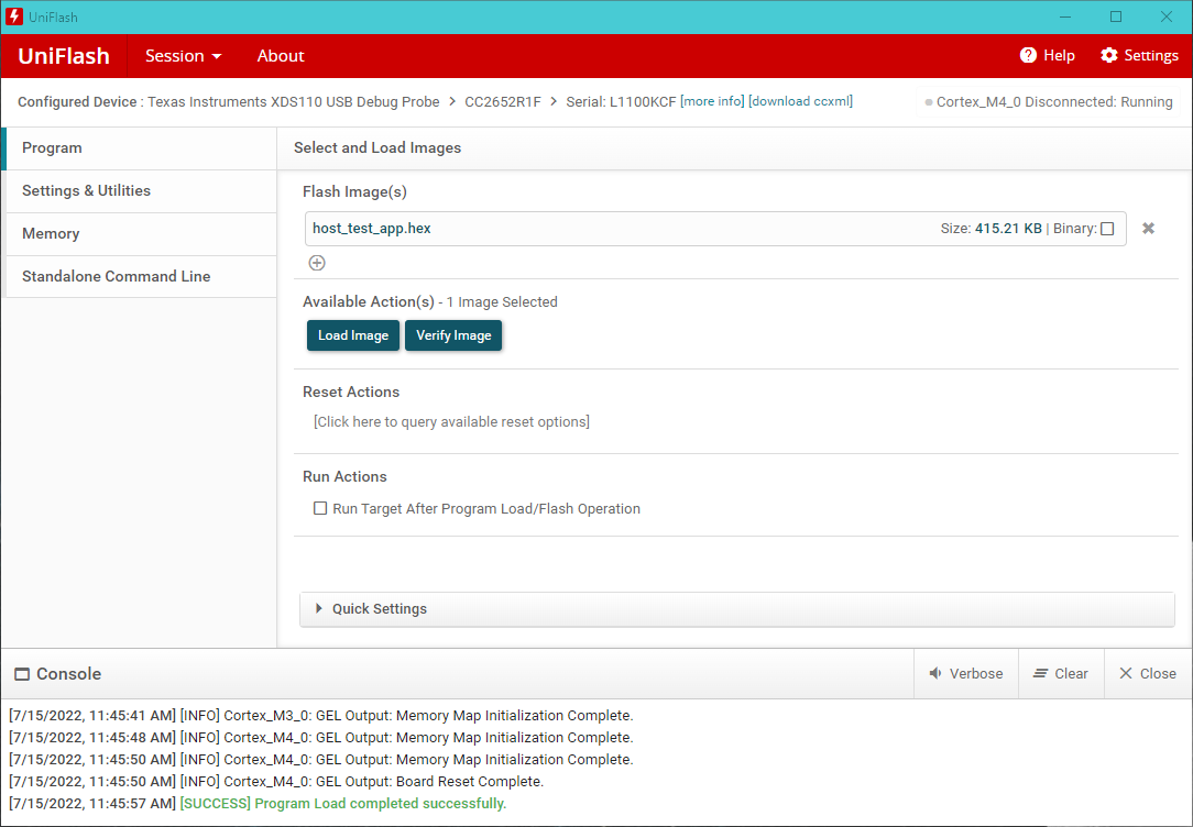
Flashing host_test with UNIFLASH#
Warning
You need to reset the HostTest application by pressing the RESET button on your Launchpad (button by the micro-USB connector) before you can open the COM port in BTool.
Connecting BTool to host_test#
BTool and host_test communicate via USB through the XDS110 UART back channel. See below for a diagram:
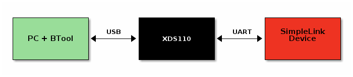
OAD Toolchain#
Find the port used by the UART backchannel of the CC13xx or CC26xx LaunchPad running host_test. This is the one with the name
XDS110 Class Application/User UART.Open BTool (see the BTool executable in the tools folder of the BLE5-Stack).
Use the following serial port settings, select OK.
Port:
<PORT_FROM_ABOVE_STEP>Other settings: 115200 8N1
This will open and initialize the host_test device.
Press the scan button and a list of discovered devices will populated in the BTOOL log.
A screen shot of a properly initialized BTool session is shown below
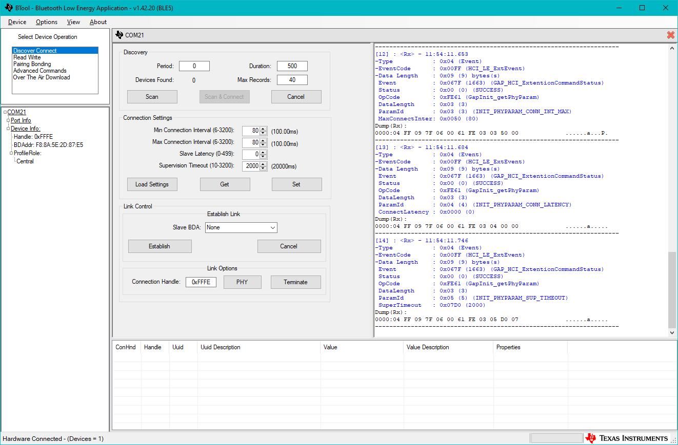
BTool Init Success#
OAD Target Setup#
As we learned in the section Anatomy of an OAD, the target device requires three images (on-chip) or two images (off-chip) to be flashed.
Use a second LaunchPad for the following steps and do not flash the host_test
board again.
The first image is the BIM. In this lab we will be using the secure release version that is available as a precompiled .hex file (or use the compiled .hex file from your BIM project):
<SDK_INSTALL_DIR>\examples\nortos\<BOARD_NAME>\bim\hexfiles\bim_onchip\Release\bim_onchip.hex
Both persistent and user applications cannot be directly flashed as a .hex file
as image header data is required for the BIM to accept the image after startup.
Instead we will be using the generated image *_oad.bin. This is automatically
generated in CCS as a pre-build step that runs the OAD Image Tool. This
applies to OAD enabled projects that have SECURITY defined, which is the
default setting for OAD projects in the SDK.
The application image for on-chip OAD is split into two parts: Persistent app and user app. Exact project and file names may differ depending on the hardware and IDE used.
Compile the Persistent App project. The
Releasefolder should now contain the OAD binarypersistent_app_<BOARD_NAME>_tirtos7_ticlang_oad.binCompile the Simple Peripheral OAD Onchip project. The
Releasefolder should now contain the OAD binarysimple_peripheral_oad_onchip_<BOARD_NAME>_tirtos7_ticlang_oad.binFlash all three images using UNIFLASH. You can flash them in one run, see below screenshot. Note the start address of
0x38000for the persistent app.
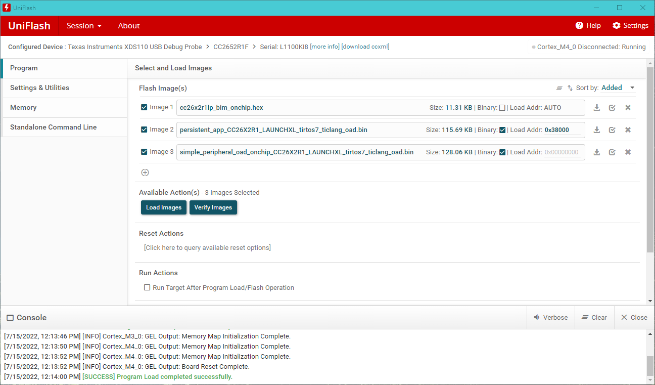
Flashing On-Chip BIM and application images#
The first image is the BIM. In this lab we will be using the secure release version that is available as a precompiled .hex file (or use the compiled .hex file from your BIM project):
<SDK_INSTALL_DIR>\examples\nortos\<BOARD_NAME>\bim\hexfiles\bim_offchip\Release\bim_offchip.hex
The application cannot be directly flashed as a .hex file as image header data
is required for the BIM to accept the image after startup. Instead we will be
using the generated image *_oad.bin. This is automatically generated in CCS as
a pre-build step that runs the OAD Image Tool.
Before building the project, we need to enable the OAD debug setting to enable additional menu options including the generation of a factory image.
Edit the SysConfig settings by opening
simple_peripheral_oad_offchip.syscfgGo to BLE → Advanced Settings → OAD Only Defins → OAD Debug
Enable
OAD Debugoption, see below
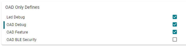
SysConfig OAD Debug Option#
Now compile the project. The folder
Releasewill contain the filesimple_peripheral_oad_offchip_<BOARD_NAME>_tirtos7_ticlang_oad.binFlash this binary file using UNIFLASH. You can flash it and the BIM image in one run, see below screenshot:
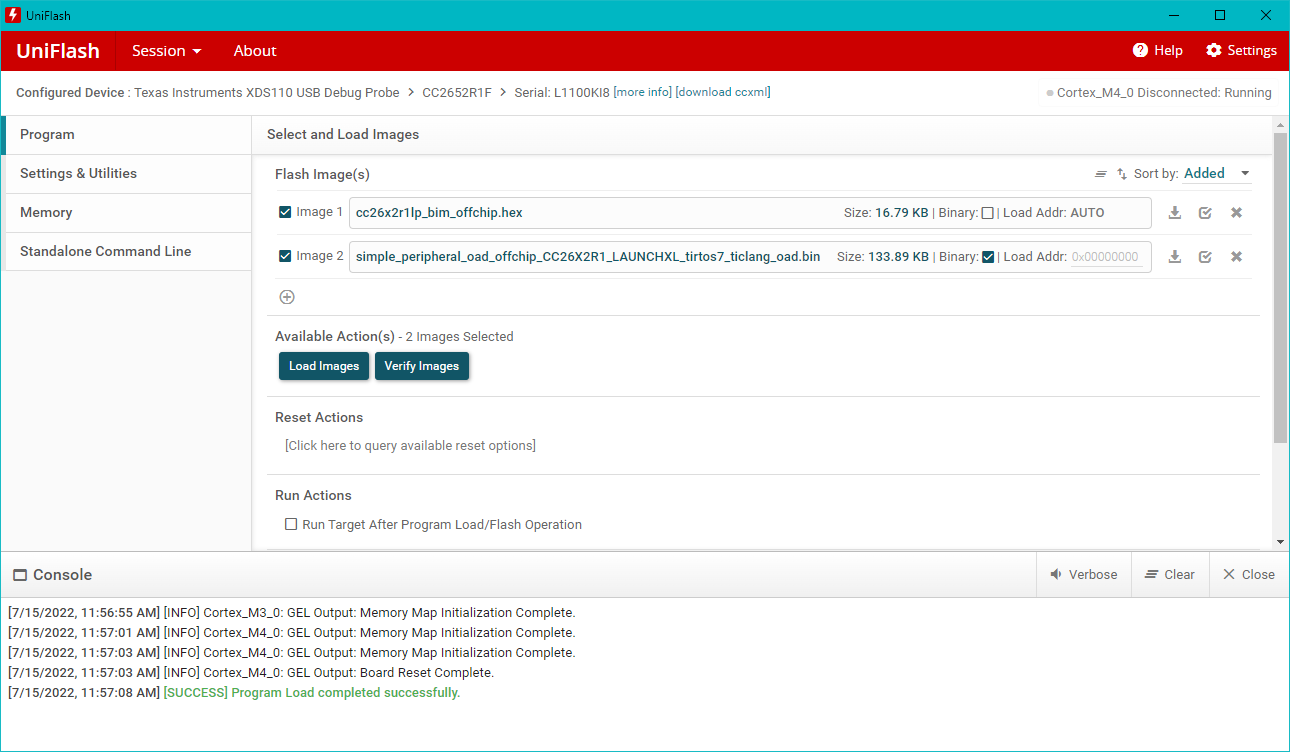
Flashing Off-Chip BIM and application image#
Warning
Once the OAD Target is set up, a reset is required to start the BIM and have it load the application image. You can reset the target by pressing the RESET button on your Launchpad (button by the micro-USB connector). At this point, you should see the application menu on a serial terminal.
Creating a Factory Image#
A factory image is a known good application image that can be used if an updated image introduced issues into the system that prevents further updates. By reverting to the factory image, the application can execute another update.
Factory images are not supported in on-chip OAD due to memory size restrictions.
Using the two button menu feature on simple_peripheral_oad_offchip input in
the following sequence:
OAD Debug → Create Factory Image.
This will overwrite the current factory image in external flash. Wait until the message Successfully created factory image appears.
In order to view the menu you will need to open the COM port on this device. For information on how to open the COM port, see the “Connect a terminal program” section of the BLE Fundamentals Lab.
Error
Do not unplug or reset the device during factory image update. This should take around 30s to complete, wait until the success message is displayed.
The menu will display the status after creating the factory image:
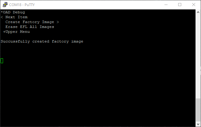
Factory Image Created#
Task 2 – Running the OAD Demo#
Now that the OAD environment is ready, we will download a new image over BLE using BTool.
Modifying the Image Version#
Modifying the image version is a quick and easy way to verify that the OAD has completed. Some sample apps will display their image version in the terminal window.
Open the file
OAD\oad_image_header_app.cwithin the project.Modify the
SOFTWARE_VERfield to increase the version number.Rebuild the application project and generate a new binary
*_oad.bin.
Warning
In CCS, the oad_image_header_app.c is linked in the project. This
means that changing this file means we have modified the source in the SDK. Due
to this, all projects that use oad_image_header_app.c will inherit the above
change, i.e. a modified SOFTWARE_VER field.
OAD using BTool#
Now switch back to BTool to perform an OAD with the new version of our application.
Connect to the OAD Target device using its “Dev Addr” (see COM port menu). The below screenshot shows how to connect to a specific Bluetooth LE peripheral’s address in BTool.
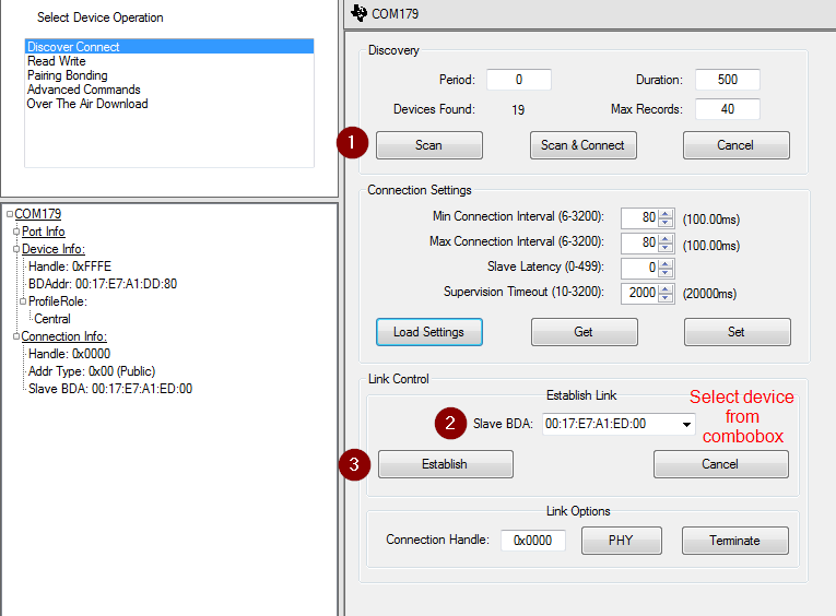
BTool Establish Connection#
Wait for the application’s connection parameter update (if enabled)
BTool will send a connection parameter update at the beginning of an OAD to attempt a faster download. By default, the `simple_peripheral_oad_xxchip`` example application will also attempt a connection parameter update 6 seconds after the connection is established (configured via SysConfig).
It is recommended to wait until the application’s connection parameter update has taken place before starting an OAD. If you are experiencing a slow OAD, this may be the cause. The parameter update is complete once the following message is shown in the BTool log:
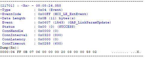
BTool Parameter Update#
Once connected, switch to the OAD tab and load an oad image into BTool
The
securecheckbox is read-only and indicates whether the currently loaded OAD image has security enabled in its header.If using on-chip OAD, be sure to un-check the box
OAD to external flashIf using off-chip OAD, be sure to check the box
OAD to external flashThe OAD process begins once the image identify is accepted.
While intermittent blocks are being sent BTool will display:
Write Block Number = x of yThe OAD process will continue until BTool displays
OAD Download Successful.
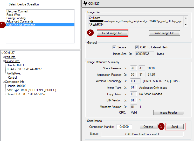
BTool OAD Process#
Warning
If the device is connected to an external debugger when performing an OAD, the device could potentially not reset properly after a successful OAD. This is a known issue, however, simply unplugging/replugging or hard reset the device will make the device boot properly. Read more about this in detail in the BLE5-Stack User’s Guide Section Halt In Boot (HIB).
For secure OAD configurations, BTool uses the default public/private key pair. To change the security keys used by the embedded device, see Generating New Security Keys (Embedded) in the BLE5-Stack User’s Guide. To change the security keys used by BTool please see the next section of this chapter.
After some delay (verification in the BIM), the new image should boot up and will be active.
Assuming the steps in Modifying the Image Version were followed, then a new image version # should be observed on the terminal display. If the version displayed on the terminal matches, then the download has completed successfully.
The menu will now display modified image version number:
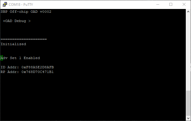
Image V2 running#
BTool Image Header Dialog#
A good way to inspect and parse the fields in the OAD Image Header for a given image is to use BTool. In this view, BTool will parse the various fields in the image header and present them in a human readable format.
This can also be used to manually change various fields of the image header and then resign/recalculate the CRC. The image header dialog can be used to modify the image version number in order to simulate upgrading to a new version of the firmware via OAD.
When using secure OAD, any change in the image header will require the image to
be re-signed as well as CRC to be recalculated. Resigning the image requires the
key files to be placed in the same folder as BTool.exe. Copy the public.pem
and private.pem files from the tools/common/oad folder into the same folder
as btool.exe.
Note
It is important that the keys match the ones that are installed on the embedded device or the image signed by BTool will be rejected due to an invalid signature.
You can access the OAD Image Header dialog using the following steps:
Start BTool normally
Navigate to the “Over The Air Download” pane
Select read image file, point this to the candidate image ending with
_oad.binClick the image header button
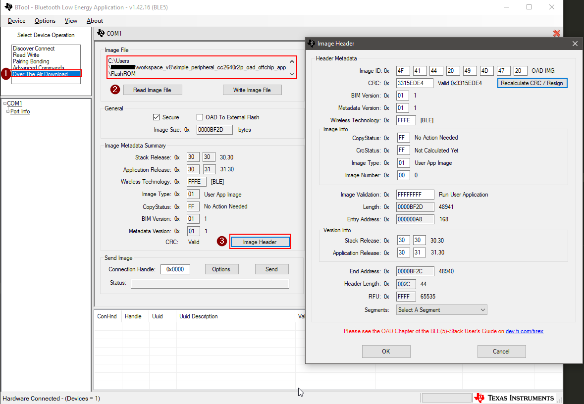
BTool OAD Image Header#
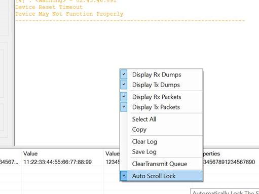
BTool OAD Speed Optimization#
The time required for the btool OAD process can be reduced by turning off the following settings of the btool UI: Right-click on the output panel on the right and de-select:
Display RX Dumps
Display TX Dumps
Display RX Packets
Display TX Packets
Auto Scroll Lock
BTool OAD Image Header#
Note
The overall OAD performance on btool is depending on the available processing power of the computer executing btool. Running other software in parallel can have a noticeable impact in the time required for the OAD process.
Further steps to improve the OAD speed are:
Increase the baud-rate of btool and host-test (requires modification and re-compiling of the host-test project)
Select the highest possible packet length, see SimpleLink Academy: Bluetooth Low Energy Enhanced Over the Air Download (OAD) Advanced
Ensure the fastest possible connection interval of 7.5 ms. For on-chip OAD, the target connection interval may be changed by the persistent app. This is done in Application/oad_persistent_app.c
  // Minimum connection interval (units of 1.25ms, 80=100ms) for parameter update request
  #define DEFAULT_DESIRED_MIN_CONN_INTERVAL     6 // = 7.5 ms, original value 80

  // Maximum connection interval (units of 1.25ms, 104=130ms) for  parameter update request
  #define DEFAULT_DESIRED_MAX_CONN_INTERVAL     6 // = 7.5 ms, original value 104
Task 3 – Revert to Factory Image#
We have now updated to a completely new application via OAD. In an actual software development cycle, it is possible that this new application may contain a bug. When designing an OAD solution, it is important to allow a downloaded application to be reverted to a known working configuration.
Factory images are not supported in on-chip OAD due to memory size restrictions.
TI has created a factory image check procedure to be performed in the
main() of the application project. The code is simple and will check the state
of a given PIN at boot, and if the PIN is asserted, it will corrupt the CRC
value of the running application and reboot.
After reboot the BIM will revert back to the factory image.
The check shall occur before any of the stacks boot or other user threads have been created. The sample applications in the SDK have aligned on using the left button on the LaunchPad to check for factory image.
For the TI OAD profile this recovery mechanism is called the factory image. In this task we will revert back to the factory image created in task 1.
Press both the reset button and the left button at the same time.
Release the reset button while leaving the left button pressed.
Continue to hold the left button for 5 seconds.
After releasing the left button, the red LED will blink and
simple_peripheralwill display the following:
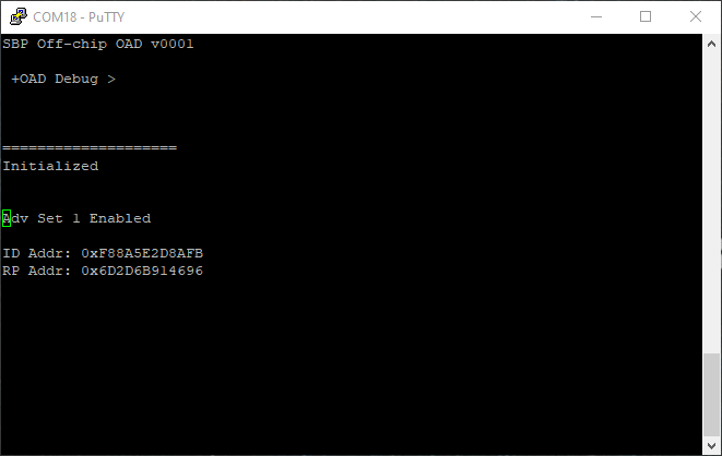
Image V1 running again#
At this point the device have booted back into the original
simple_peripheral_oad_offchip image.
Warning
The application should check that a valid factory image is present before invalidating itself. It can do so by ensuring there is valid metadata in external flash page 0. See the chapter OAD External Flash Image Header in the BLE5-Stack User’s Guide.