Introduction
Global Load Feature
Many Applications will have EPWMs with runtime updates to their CMP/TBPRD/Action Qualifier/ DeadBand Registers etc, that affect the EPWM Outputs. Care needs to be taken while updating these registers so that there wouldn't be any incorrect/unexpected/corrupted waveforms while these updates happen. To tackle with such issues, the EPWMs have been equipped with a Global Load feature. Along with the Shadow to Active load strobe for individual register sets, there is optional Global load strobe, if enabled, overwrites the local load strobe. The global load strobe can be used for activating all shadow to active transfers, this will result in retaining the older EPWM outputs untill all the shadow registers are updated, resulting in no currupted waveforms in between.
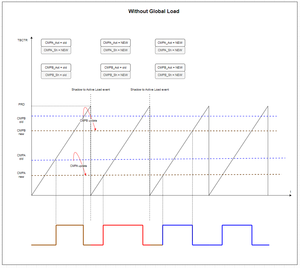
EPWM Without Global Load Feature
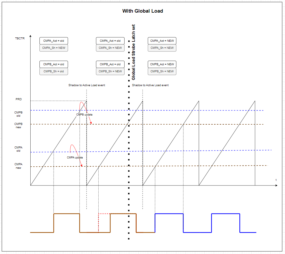
EPWM With Global Load Feature
Link Feature
Link Feature helps link the EPWMs to have simultaneous updates to the link enabled registers like TBPRD/CMP(A/B/C/D)/DBFED/DBRED/GLDCTL2, when these registers in the linked EPWMs are written to.
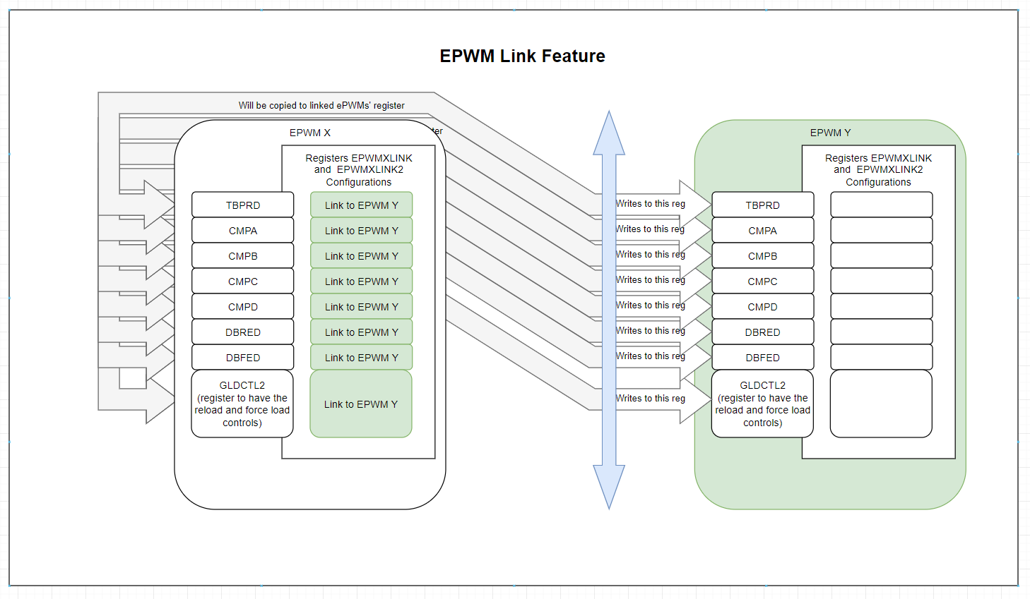
EPWMs With Link Feature
Example Description
This Example aims to showcase the Global Load and Link features usage.
Configurations
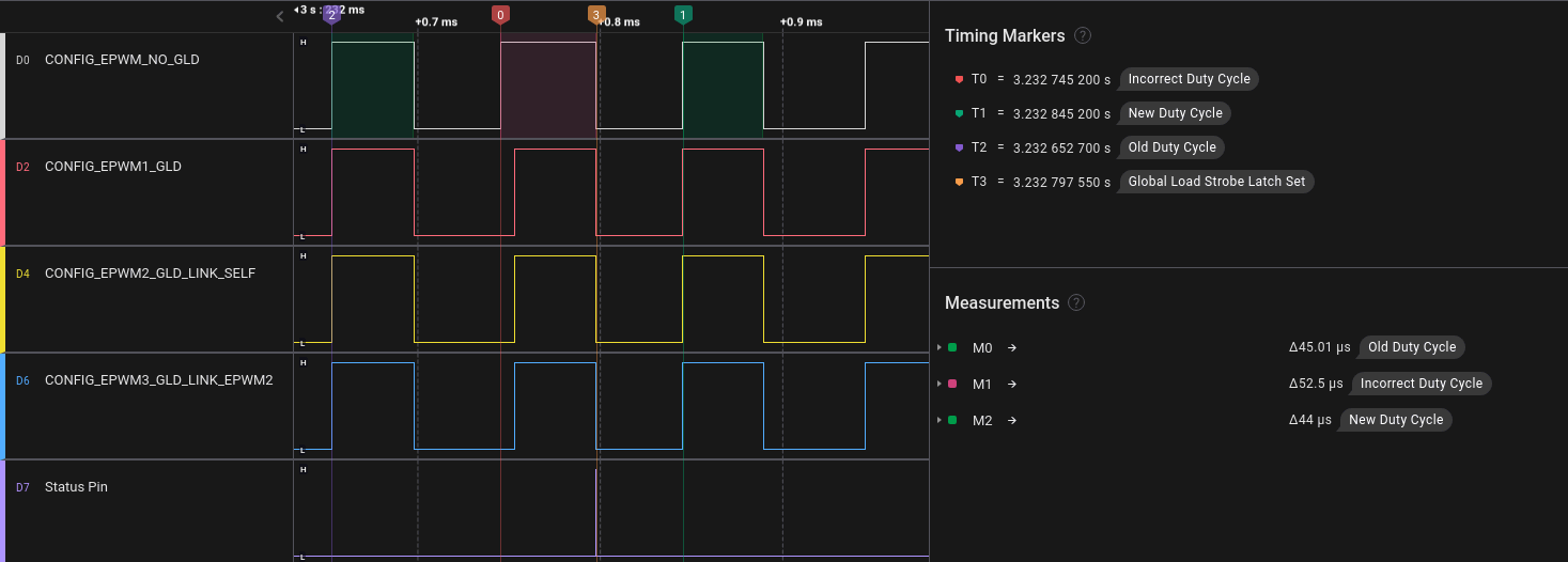
4 EPWMs..,
- CONFIG_EPWM_NO_GLD : no Global Load is configured
- CONFIG_EPWM1_GLD : Global Load is configured.
- CONFIG_EPWM2_GLD_LINK_SELF : Global Load is configured. CMP(A/B)/ GLD Controls Linked to self
- CONFIG_EPWM3_GLD_LINK_EPWM2 : Global Load is configured. CMP(A/B)/ GLD Controls Linked to CONFIG_EPWM2_GLD_LINK_SELF.
Apart from the Global load or Link configurations, all EPWMs are configured similarly. Check the Syscfg for the Global Load Configurations and differences.
- Note
- Shadow registers are used for CMP, TBPRD regs, while global load is only used on the CMP regs and Link is used for CMP and GLD controls.
External Connections.
Probe the EPWM outputs for the above EPWMs and Status pin.
AM263Px or AM263x Control Card with HSEC 180 Pin out
- CONFIG_EPWM_NO_GLD : EPWM 0A/0B on HSEC pins 49/51
- CONFIG_EPWM1_GLD : EPWM 1A/1B on HSEC pins 53/55
- CONFIG_EPWM2_GLD_LINK_SELF : EPWM 2A/2B on HSEC pins 57/59
- CONFIG_EPWM3_GLD_LINK_EPWM2 : EPWM 3A/3B on HSEC pins 61/63
- Status Pin : GPIO on HSEC pin 50
AM263Px or AM263x Launch Pad
- CONFIG_EPWM_NO_GLD : EPWM 0A/0B on BoosterPack J4 11 / J8 59
- CONFIG_EPWM1_GLD : EPWM 1A/1B on BoosterPack J2 37 / J2 38
- CONFIG_EPWM2_GLD_LINK_SELF : EPWM 2A/2B on BoosterPack J2 39 / J2 40
- CONFIG_EPWM3_GLD_LINK_EPWM2 : EPWM 3A/3B on BoosterPack J8 77 / J8 78
- Status Pin : GPIO on J8 52
Supported Combinations
| Parameter | Value |
| CPU + OS | r5fss0-0 nortos |
| Toolchain | ti-arm-clang |
| Board | am263x-cc, am263x-lp |
| Example folder | examples/drivers/epwm/epwm_global_load_and_link/ |
Steps to Run the Example
- When using CCS projects to build, import the CCS project for the required combination and build it using the CCS project menu (see Using SDK with CCS Projects).
- When using makefiles to build, note the required combination and build using make command (see Using SDK with Makefiles)
- Establish connections as mentioned in External Connections section
- Launch a CCS debug session and run the executable, see CCS Launch, Load and Run
See Also
EPWM
Sample Output
Shown below is a sample output when the application is run,
EPWM Global Load and Link Test Started ...
EPWM Global Load and Link Test Passed!!
All Tests have Passed!
EPWM Global Load and Link Example Sample Output
 1.8.20