# Overview
This guide is intended for users with an xWR6843 TI mmWave sensor evaluation module (EVM).
The guide will walk through setting up the DCA1000 capture card as well as the mmWave Studio
tool in order to configure the device's mmWave SDK Front End software to allow for raw data collection.
This guide supports several different EVMs, so be sure to follow the steps
that apply to your device.
---
# Software Requirements
| Requirement | Description | Link |
|--------|------------------|-----------|
| mmWave Studio | Software tool to configure mmWave characteristics, make sure you download the 1st generation installer | [mmWave Studio Download](https://www.ti.com/tool/MMWAVE-STUDIO)<br><br>[User Guide](https://www.ti.com/lit/ug/swru529c/swru529c.pdf?ts=1652736281356&ref_url=https%253A%252F%252Fwww.ti.com%252Ftool%252FMMWAVE-STUDIO)</br>
| MatLab Runtime Engine v8.5.1 | <b>This specific version is REQUIRED</b>, Make sure to install this version even if you have a newer one already installed. | [MatLab Download](https://www.mathworks.com/supportfiles/downloads/R2015a/deployment_files/R2015aSP1/installers/win32/MCR_R2015aSP1_win32_installer.exe)
| Code Composer Studio v7.1+ <b>OR</b> <br> XDS Emulation Software Package v6.0.579.0+| <b>Required Software</b>, only need one of the software listed for this user guide | [Code Composer Studio Download](https://www.ti.com/tool/CCSTUDIO#downloads)<br><br>[XDS Package Download](https://software-dl.ti.com/ccs/esd/documents/xdsdebugprobes/emu_xds_software_package_download.html)
---
# Hardware Requirements
| Requirement | Description |
|--------|------------------|
| [xWR Sensor EVMs](https://www.ti.com/design-resources/embedded-development/industrial-mmwave-radar-sensors.html#Evaluation)| mmWave EVM, needs a Power Supply 5V, 3A with 2.1-mm barrel jack (center positive), micro USB cable (this cable come with kit) |
| [DCA1000 EVM](https://www.ti.com/tool/DCA1000EVM) | Raw data capture card, needs a Power Supply 5V, 3A with 2.1-mm barrel jack (center positive), micro USB cable, RJ45 Ethernet cable, 60pin Samtec cable (this cable comes with kit) |
| Barrel Jack Power Supply | Power Supply 5V, 3A with 2.1-mm barrel jack (center positive) |
| Micro USB Cable | Two cables are required if using a setup that includes an ICBOOST |
| Ethernet Cable | One end will be plugged into the DCA1000 and the other to your computer for high speed data transfer|
---
# EVM Hardware Compatibility
Certain versions of xWR mmWave Sensors require an ICBOOST for raw data capture. Below is a table of all EVM revisions that do or do not need an ICBOOST.
| mmWave EVM | DCA1000 Only | DCA1000 + ICBOOST |
|-----|-----------|---------------|
| xWR6843ISK Rev A - C| <b><p>✕</p></b> | <p>✔</p> |
| xWR6843ISK Rev D | <p>✔</p> | <p>✔</p> |
| xWR6843ISK-ODS Rev A | <b><p>✕</p></b> | <p>✔</p> |
| xWR6843ISK-ODS Rev B | <p>✔</p> | <p>✔</p> |
| xWR6843AOP Rev A - F | <b><p>✕</p></b> | <p>✔</p> |
| xWR6843AOP Rev G | <p>✔</p> | <p>✔</p> |
---
# Hardware Setup: ISK and ISK-ODS Evaluation Modules
This section applies to the following boards:
* [xWR6843ISK](http://www.ti.com/tool/IWR6843ISK)
* [xWR6843ISK-ODS](http://www.ti.com/tool/IWR6843ISK-ODS)
## EVM Standalone Mode
* This section describes setting all non-AOP EVMs to the proper hardware configuration for raw data.
* Using the EVM Hardware Combinations and Compatibility table above, verify your revision of EVM can collect raw data from the DCA1000 without requiring a ICBOOST board.
[[+d Expand for steps on hardware setup of an EVM Standalone only
### Additional Hardware Requirements for Standalone ISK Style
* ISK or ISK-ODS Antenna Module Board <b> Rev D or newer </b>
### Switch and Wiring Setup with Antenna Module and DCA1000
<b>Note:</b><br>
The step below only applies when using the xWR6843ISKEVM RevD antenna module or xWR6843ISK-ODSEVM RevD without an ICBOOST.
This information can be found in the ICBOOST users guide at: https://www.ti.com/lit/ug/swru546c/swru546c.pdf<br><br>
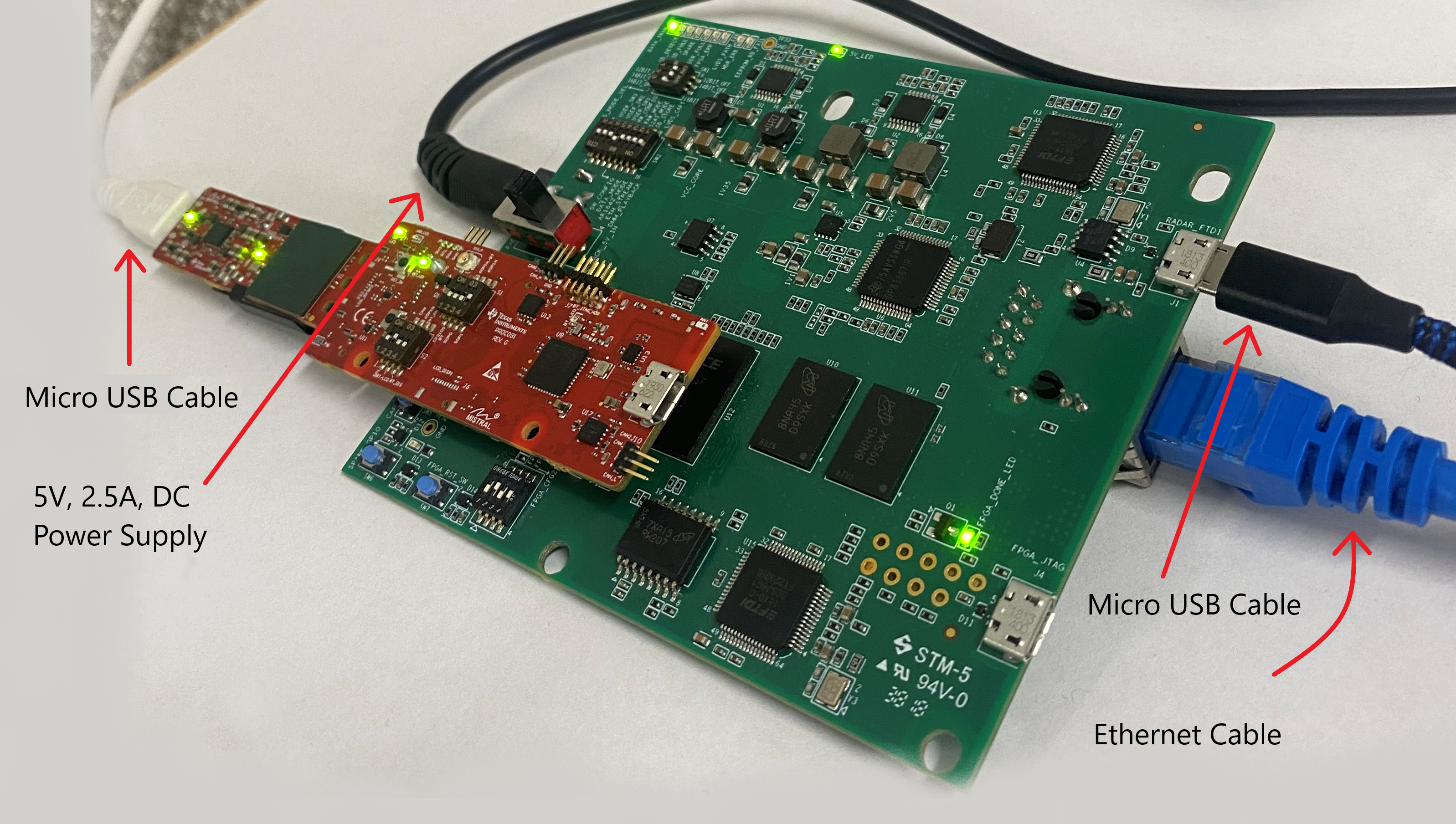
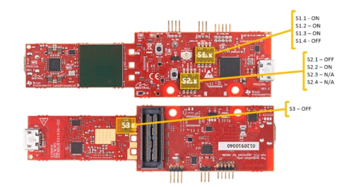
To use RevD EVM directly with DCA1000, the switches (in the yellow circle) need to be set as shown below.
On the RevD board, power is supplied via USB connector. (For 3TX and other high power use case that exceeding the limit of the USB power input, TP12 & TP13 can be used to power the antenna board)
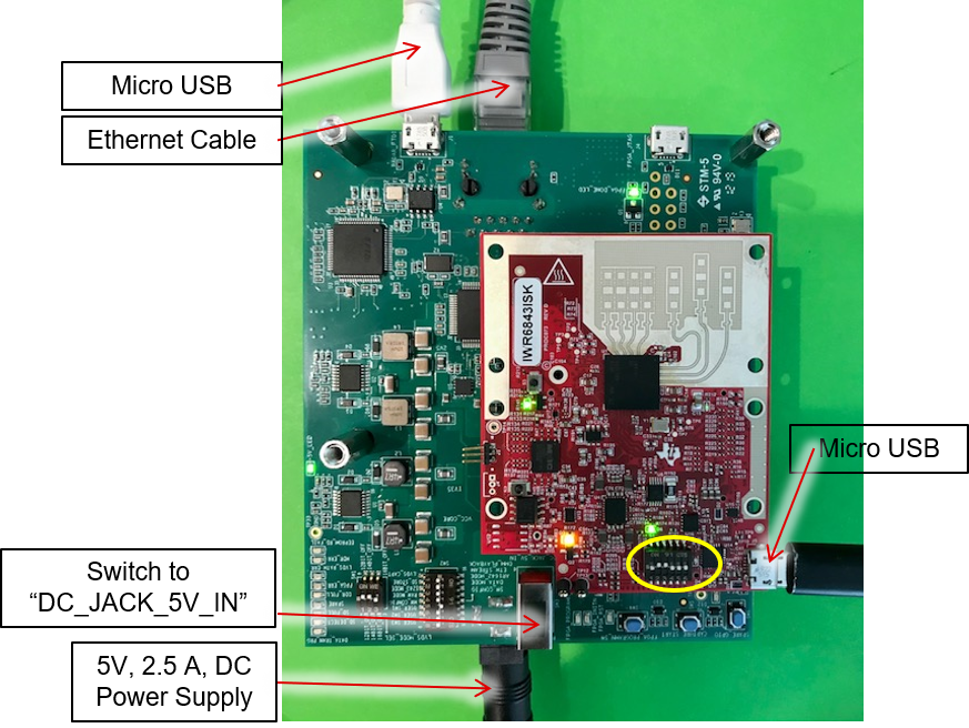<br>
Flip the large DCA1000 switch if none of the LEDs on it light up.
+]]
## EVM With mmWaveICBoost Attached
* This section describes setting up the hardware for an ISK style EVM attached to an mmWaveICBoost ICBOOST.
[[+d Expand for steps on hardware setup of an ISK with an mmWaveICBoost
### Additional Hardware Requirements for ISK + Carrier
* [MMWAVEICBOOST](http://www.ti.com/tool/MMWAVEICBOOST)
* ISK or ISK-ODS Antenna Module Board
* Additonal Micro USB Cable
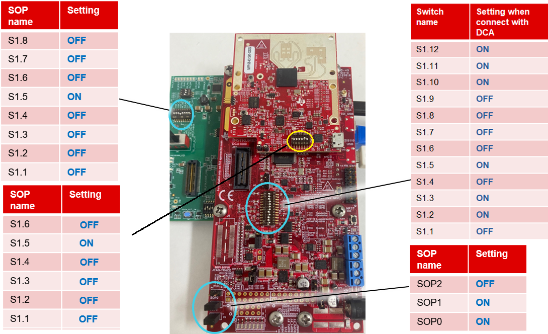
### ISK + Carrier and DCA1000 Setup
#### Configure mmWaveIcBoost
If the mmWaveICBoost ICBOOST has not been used previously,
then change the switches on the boards to the following states.
On *newer* EVM's (Only ISK Rev C or later and ISK-ODS Rev B or later have switches
on the EVM itself)
that have not been previously used in conjunction with the carrier
board, set the switches according to the following image
#### Wiring Setup with ISK and DCA1000
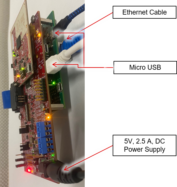
Flip the large DCA1000 switch if none of the LEDs on it light up.
+]]
---
# Hardware Setup: AOP EVM's
This section applies to the following boards:
* [xWR6843AOPEVM](https://www.ti.com/tool/IWR6843AOPEVM)
## AOP Standalone Mode
* Section applies to setting an AOP EVM for Raw Data Collection via DCA1000
when used **without** an mmWaveICBoost ICBOOST.
[[+d Expand for steps on hardware setup of an AOP EVM only
### Additional Hardware Requirements for Standalone AOP
* AOP Antenna Module <b> Rev G or newer </b>
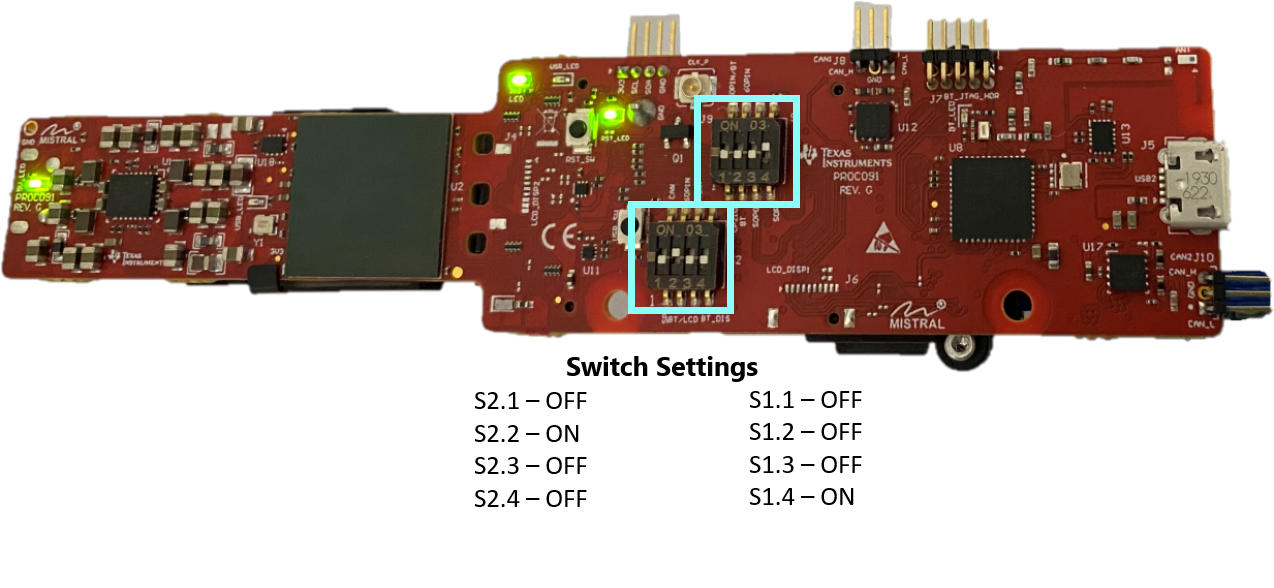
### Switch and Wiring Setup with AOP RevG and DCA1000
This step only applies when using the xwr6843AOP RevG antenna module without an ICBOOST, any other revision must have
a mmWaveICBOOST. To use RevG EVM directly with DCA1000, the switches (highlighted with blue squares) need to be set as shown.
Note that on RevG board, power is supply via USB connector.
Flip the large DCA1000 switch if none of the LEDs on it light up.
+]]
## AOP With mmWaveICBoost Attached
This section describes setting up the hardware for an AOP EVM when attached to an mmWaveICBoost ICBOOST.
Please note the switch orientation as well as the amount of connected
cables
[[+d Expand for steps on hardware setup of an AOP EVM with an mmWaveICBoost
### Hardware Requirements for AOP + Carrier
* [MMWAVEICBOOST ICBOOST](http://www.ti.com/tool/MMWAVEICBOOST)
* AOP Antenna Rev A-G Module Board
* Additional Micro USB Cable
### Configure AOP Switches
### Configure mmWaveIcBoost Switches

### Wiring Setup

Flip the large DCA1000 switch if none of the LEDs on it light up.
+]]
---
# Software Setup: Preparing mmWave Studio to read mmWave EVM
Perform the following setup steps:
* Install FTDI and XDS Drivers
* Install [MatLab Runtime Engine v8.5.1](https://www.mathworks.com/supportfiles/downloads/R2015a/deployment_files/R2015aSP1/installers/win32/MCR_R2015aSP1_win32_installer.exe), this specific version is REQUIRED
* Install mmWave Studio
* Setup Static IP for Ethernet Data Transfer
[[+d Expand for steps on FTDI and XDS driver installation
If you do not have Code Composer Studio v7.1 or higher installed:
1. Install the XDS Emulation Software Package from the link at the top of this page.
2. Connect the DCA1000 and the EVM to your PC through USB cables and power.
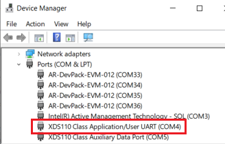
3. In the Windows Device Manager, the COM ports should appear as this when the drivers are installed:

The FTDI device ports of the DCA1000 board will appear with a yellow label when the driver is not installed:

* In this case, right-click on this symbol, select “Update Driver Software”, “Browse my computer for driver software”, select the below directory, and tick “Include subfolders”.~\mmwave_studio_xx_xx_xx_xx\ftdi
* This needs to be done for each of the 4 ports. In some cases you might need to do it twice for the 1st port or each of the 4 ports.
+]]
[[+d Expand for steps on mmWave Studio installation
1. Grab the mmWave Studio installer from the link specified at the top. The user guide is also linked with more detailed instructions on how to install if needed.
2. After the installation is complete, the GUI executable and associated files will
reside in the following directory: C:\ti\mmwave_studio_ver\mmWaveStudio
3. If all other setup steps have been completed, go to "Running mmWave Studio"
+]]
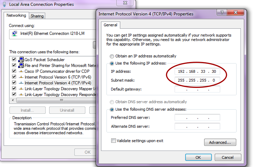
[[+d Expand for steps on Static IP configuration for Ethernet Data Transfer
1. Connect the Ethernet cable between the DCA1000 and the PC.<br>
2. In the PC local area network properties select TCP/IPv4.<br>
3. Set static IP address of 192.168.33.30.<br>
4. Subnet mask as 255.255.255.0<br>
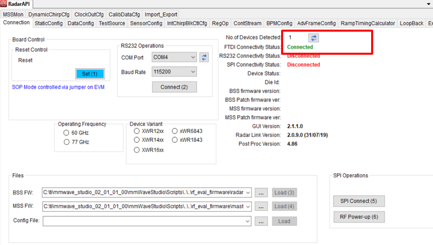
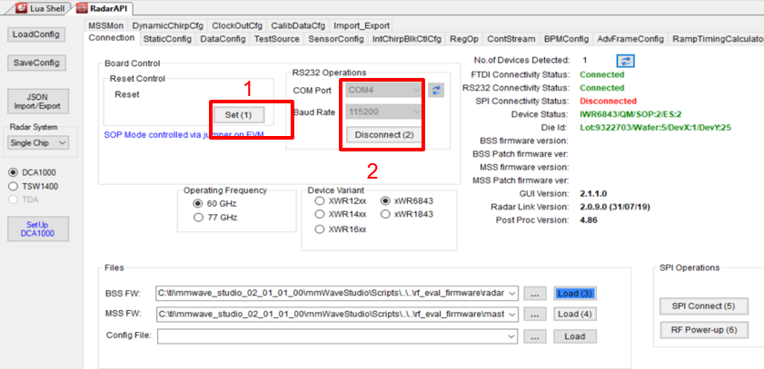
5.1. Open mmWaveStudio and the RadarAPI tab.<br>
5.2. Under “Reset Control” click ‘Set(1)’<br>
5.3. Under “RS232 Operations” Select the COM port listed in device manager as Application/User port number, set the Baud rate 115200.<br>
5.4. Click ‘Connect’. The RS232 Connectivity should turn to ‘Disconnect’. The Device status should show based on the radar device used.<br>
+]]
# Running mmWave Studio
By this point, all hardware and software setup must be completed successfully.
[[+d Expand for full instructions on how to use mmWave Studio to read raw data
### 1.
* Ensure your hardware is properly connected and everything is powered on.
* To start the GUI, click on the Desktop shortcut for mmWave Studio or open the file called “mmWaveStudio.exe", located within C:\ti\mmwave_studio_<ver>\mmWaveStudio\RunTime folder.
<br><b>*NOTE:*</b> For your first time running mmWave Studio, your hardware must already be connected or the program will not open correctly.
* The Connection window should show up with FTDI Connectivity highlighted in green. If in red, install the FTDI drivers (see section FTDI and XDS driver installation within Software Setup).
### 2.
* “Under Reset Control” click ‘Set(1)’
* “RS232 Operations” Select the COM port listed in device manager as Application/User port number, Baud rate 115200.
Click ‘Connect’. The RS232 Connectivity should turn to ‘Disconnect’. The Device status should show based on the radar device used.
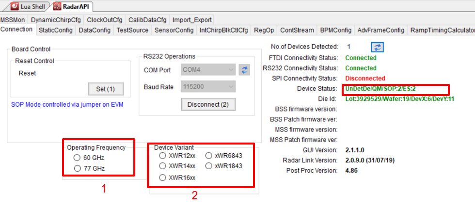
<br><b>*NOTE: *</b>The portion below is only applicable to an AOP device.
When using an AOP device, the device name is not automatically detected after hitting reset and disconnect under RS232 connection. The user has to click the “operation frequency” and “device variant” radio buttons manually in the specific order shown below. Any deviance from the suggested order can cause unwanted errors.
### 3.
* “Files” load the appropriate BSS (radarss.bin) , then MSS firmware (Masterss.bin) from the “~\mmwave_studio_<ver>\rf_eval_firmware” folder. The binary is based on the device variant being used (1243/1443/1642/6843)
* The silicon PG version (ES1.0, ES2.0, ES3.0) being supported by the firmware is listed in the radar studio release notes. The firmware for an older PG version can be found in the older version of the radar studio.
* “SPI Operations” Click ‘SPI Connect(5)’ then ‘RF Power-up(6)’
* Once the firmware is loaded, the firmware and patch versions are displayed.

### 4.
#### StaticConfig tab:
* Select the desired TX and RX channels that you would want to use. In ADC Config, select desired ADC configuration and click SET
* If board is provided 1V RF supply Enable the RF LDO Bypass, if its 1.3V leave it unchecked. Click the Advanced Configuration Set button.
* LP mode select ‘Regular ADC’ mode
* Click the RF Init Done button.

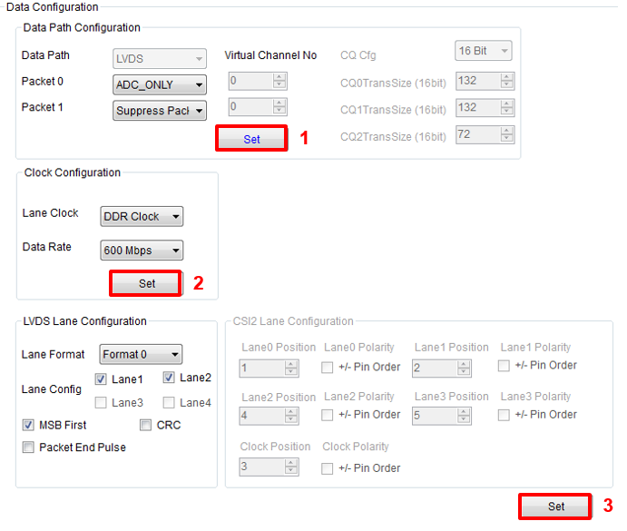
#### DataConfig tab:
* Select the data path config (ADC_ONLY) and click Set button.
* Select the clock rate and click set.
* Select the LVDS lanes and click set.
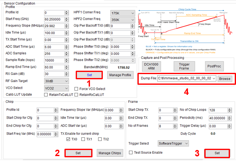
#### SensorConfig tab:
* Select the required Profile configuration. These define the FMCW chirp profile.
* Select the chirp configuration.
* Select the frame configuration.
* Select the Dump file path name.
* For more details on selecting the values for profile , chirp and frame configuration refer to the app note [Programming Chirp Parameters in TI Radar Devices](http://www.ti.com/lit/pdf/swra553)
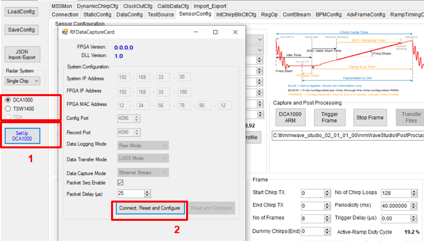
### 5.
* Select ‘DCA1000’ and click on ‘SetUp DCA1000’
* Click on “Connect, Reset and configure”. This would establish the Ethernet connection and display the FPGA versions. Verify that the FPGA version is correct.
* Note that in case the connection fails make sure the static IP is set correctly, Ethernet cable is plugged in correctly, WIFI is disabled and the ports 4096 and 4098 are accessible in the PC used, i.e. there is no firewall blocking the ports.
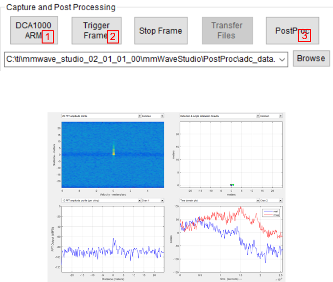
### 6.
* Click on DCA1000 ARM and then Trigger Frame. At this point the radar starts sending out ADC data and DCA1000 starts capturing it.
* Once the capture is complete , click on ‘Post Proc’.
* At this point the .bin file specified in the “Dump File” dialog box is created and the captured data is processed.
* The post processing utility displays the FFT, time domain and other analyses plots. Please refer to the mmWave studio user guide for details. (The source code of this post processing utility is not available. But a data parsing script is provided with the radar studio release package located at: C:\ti\mmwave_studio_xx_xx_xx_xx\mmWaveStudio\MatlabExamples\singlechip_raw_data_reader_example\)
*Below are some of the Post Proc plots available:
Range-Angle plot
Time domain plot
2D FFT amplitude profile
1D FFT amplitude profile
Phase stability across Chirps
Amplitude stability across Chirps
Noise Cloud plots
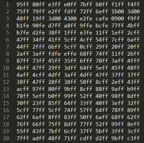
### 7.
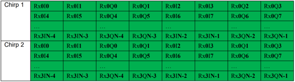
#### Data File Structure:
* Configuration:
n LVDS Lanes, complex data, n channels, chirping/continuous streaming mode
*Notation:
RxkIn: The nth in-phase sample corresponding to kth RX channel.
RxkQn: The nth quadrature-phase sample corresponding to kth RX channel.
N: The number of samples per chirp.
*Note that since the data is captured using a UDP protocol over Ethernet interface , there could be occasional packets drops. The data from the dropped packets is filled with zeros in the file and can be ignored for analyses.
#### Data File Example:
* From mmWave studio the raw ADC data (without any headers) is stored in the file name provided sensor config window.
* The data format remains unchanged in the ‘continuous streaming’ mode where one can think of the data collected as belonging to a single large chirp.
* For more details on file format refer to the mmWave studio user guide and the mmWave Radar Device ADC Raw Data Capture app note.
+]]
# Need More Help?
* Check out the [DCA1000 Training video](https://training.ti.com/dca1000-training-video)
* Refer to the [DCA1000EVM Data Sheet](https://www.ti.com/lit/ug/spruij4a/spruij4a.pdf)
* Consult the [DCA1000 Debugging Handbook](./dca1000_debugging_handbook.pdf)
* Consult the [mmWaveICBoost and Antenna Module User's Guide](http://www.ti.com/lit/pdf/swru546)
* Search for your issue or post a new question on the [mmWave E2E forum](https://e2e.ti.com/support/sensor/mmwave_sensors/f/1023)