Introduction
Welcome to the MSP430 I2C Academy. This lab demonstrates both master and slave I2C modes of operation using the MSP430FR2433 and its integrated enhanced Universal Serial Communication Interface (eUSCI) module.
This lab uses MSP430Ware register level code examples from MSP430Ware and has 3 tasks consisting of the following activities:
- Program MCU slave I2C
- Program MCU master I2C and demonstrate master to slave basic communications
- Modify master I2C code to read from a sensor on BOOSTXL-BASSENSORS BoosterPack
- Modify slave I2C code to emulate an I2C sensor
Prerequisites
Hardware
The following hardware is required for this lab
- (2) MSP-EXP430FR2433 LaunchPad
- BOOSTXL-BASSENSORS BoosterPack Module
- Jumper wires
Not required but recommended to help with understanding I2C communication
- Logic analyzer
Software
Installing the software
NOTE:
The software example used for this lab should be imported from the TI Resource Explorer. This can be accessed from the web or locally in CCS by clicking View->Resource Explorer. Before importing a project, you first need to download MSP430Ware to be able to import the examples to the CCS IDE. This may be done when CCS was installed or can be done later by clicking the "Download and Install" icon in the top right. Note that installing MSP430Ware for any project will install ALL labs and content, so this only needs to be done once.
Recommended Resources
These training videos provide a baseline introduction to the I2C protocol and hardware. The documentation can be referenced for the MSP430 MCU and the launchpad details.
- I2C: Hardware Overview
- I2C: Protocol Overview
- MSP430FR2433 MCU Datasheet
- MSP430FR4xx_2xx MCU UserGuide
- MSP430 MCUs Development Guide Book
- Solutions to Common eUSCI and USCI Serial Communication Issues on MSP430 MCUs
- Understanding the I2C Bus
Overview
This lab introduces I2C operations on MSP430 MCUs by building on the material introduced in I2C Precision Labs Training Series. The scope of this training academy is on the I2C initialization, operation, and interrupt handling portion of the code examples. Portions of the code examples related to the MCU's clock and GPIO initialization and other MCU housekeeping tasks may be presented for context, but are left up to the reader to investigate separately through topic-specific TI Academy training.
In this lab, there are two LaunchPads. In task 1 you will program one LaunchPad with the I2C slave code example. In task 2, you will program the other LaunchPad with the I2C master code example and demonstrate basic I2C read and write operations between the master and slave devices. In task 3 you will have the opportunity to use your I2C knowledge to modify the I2C master to be able to read data from the OPT3001 optical sensor installed on the BOOSTXL-BASSENSORS BoosterPack module. In task 4 you will be challenged to take your I2C knowledge one step further by modifying the I2C slave to emulate the I2C behavior of a sensor, such as the OPT3001.
Getting Started
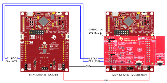
Hardware Setup:
Important
The BoosterPack provides the necessary pull-up resistors for the I2C communication, so it should remain on the boards even when not in direct use.
To connect the MSP430 launch pads for I2C communication:
- Attach the BOOSTXL-BASSENSOR module to either launchpad
- Using jumper wires, make 4 connections between the two launchpads.
- Choose one of the EXP-MSP430FR2433 launchpads to be configured as the I2C master device and the other as an I2C slave device
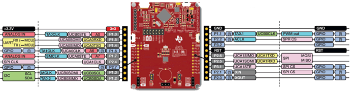
Launchpad Wiring diagram:
Launchpad Boosterpack Pinout
Task 1 – Import and Program Slave I2C Device
Example Project Overview
The purpose of task 1 is to select one of the MSP430FR2433 LaunchPads and program it with the I2C slave code example below. For this task, no modification to the code example is required.
- Import the I2C slave example msp430fr243x_eusci_i2c_standard_slave.c into CCS from TI Resource Explorer.
MSP430ware→Development Tools→MSP-EXP430FR2433→Peripheral Examples→Register Level→MSP430FR2433→
msp430fr243x_eusci_i2c_standard_slave.c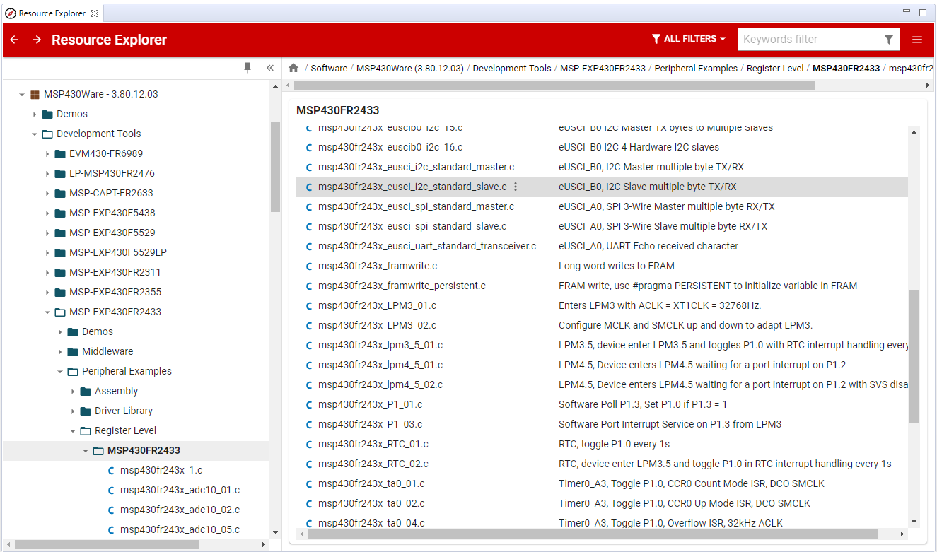
- Click Import in the upper right-hand corner
- Program the launchpad and designate this as your
I2C slavelaunchpad for future tasks.
Code Overview
Starting in function main(), the typical housekeeping tasks, such as disabling the watchdog timer, configuring the system clocks, initializing the general-purpose input-output pins (GPIO), and configuring the I2C peripheral in slave mode are performed. The code then places the MSP430 into a low power mode where the CPU will remain halted until a byte is received from the I2C master. When an I2C command is received, along with the matching slave address, an I2C interrupt is generated, waking the CPU from its low power mode. The code will then processes the received command in the I2C interrupt service routine (ISR) handler. When the processing is completed, the code exits from the ISR handler and the CPU returns to its low power mode.
    //******************************************************************************
    // Main ************************************************************************
    // Enters LPM0 and waits for I2C interrupts. The data sent from the master is  *
    // then interpreted and the device will respond accordingly                    *
    //******************************************************************************

    int main(void) {
        WDTCTL = WDTPW | WDTHOLD;    // Stop watchdog timer

        initClockTo16MHz();
        initGPIO();
        initI2C();

        __bis_SR_register(LPM0_bits + GIE);
        return 0;
    }
main()
Let's take a look at the I2C initialization steps. Before modifying any registers, always put the eUSCI module into its reset state, UCB0CTLW0=UCSWRST.
Next, configure the eUSCI module as a synchronous I2C peripheral, UCB0CTLW0 |= UCMODE_3 | UCSYNC. We must also provide our I2C slave with an I2C bus address, else, we won't be able to communicate with the I2C master. In this code example, we use SLAVE_ADDR = 0x48 and it is configured by UCB0I2COA0 = SLAVE_ADDR | UCOAEN.
That's it! The eUSCI module can then be released from its reset state, UCB0CTLW0 &= ~UCSWRST.
One last thing to configure are the interrupts. Interrupts are used to notify the CPU when certain I2C events have occurred during an I2C transaction. In our code example, we want to know when there is data in the receive register and if a STOP BIT has occurred, indicating the end of the I2C transaction.
To capture both of these events we enable their corresponding interrupt enable bits, UCB0IE |= UCRXIE + UCSTPIE.
    void initI2C()
    {
        UCB0CTLW0 = UCSWRST;                      // Software reset enabled
        UCB0CTLW0 |= UCMODE_3 | UCSYNC;           // I2C mode, sync mode
        UCB0I2COA0 = SLAVE_ADDR | UCOAEN;         // Own Address and enable
        UCB0CTLW0 &= ~UCSWRST;                    // clear reset register
        UCB0IE |= UCRXIE + UCSTPIE;
    }
I2C Slave Initialization
Next, let's take a look at the commands and state machine that processes these commands.
For the I2C transaction between the master device and slave device to work, both devices must have an agreement on how data is represented. In this case, the command definitions shown below are used in both the I2C slave and master code examples.
There are six command types defined; CMD_TYPE_X_MASTER and CMD_TYPE_X_SLAVE types. CMD_TYPE_X_MASTER commands represent data that the I2C master will write to the I2C slave's corresponding receive buffers. CMD_TYPE_X_SLAVE commands represent data that the I2C master will read from the I2C slave's corresponding transmit buffers. Notice that there is a different command based on the size or amount of data in the transaction. Note, these commands are completely arbitrary, but one possible use for the three CMD_TYPE_X_SLAVE commands could be used to represent the I2C slave's information such as an ID, the current time, location, or other information. For this example, the CMD_TYPE_X_SLAVE are assigned arbitrary values.
    #define SLAVE_ADDR  0x48

    /* CMD_TYPE_X_SLAVE is an example command the master sends to the slave.
    * The slave will send example SlaveTypeX buffers in response.
    *
    * CMD_TYPE_X_MASTER is an example command the master sends to the slave.
    * The slave will initialize itself to receive MasterTypeX example buffers.
    * */

    #define CMD_TYPE_0_SLAVE      0
    #define CMD_TYPE_1_SLAVE      1
    #define CMD_TYPE_2_SLAVE      2

    #define CMD_TYPE_0_MASTER      3
    #define CMD_TYPE_1_MASTER      4
    #define CMD_TYPE_2_MASTER      5

    #define TYPE_0_LENGTH   1
    #define TYPE_1_LENGTH   2
    #define TYPE_2_LENGTH   6

    #define MAX_BUFFER_SIZE     20

    /* MasterTypeX are example buffers initialized in the master, they will be
    * sent by the master to the slave.
    * SlaveTypeX are example buffers initialized in the slave, they will be
    * sent by the slave to the master.
    * */

    uint8_t MasterType2 [TYPE_2_LENGTH] = {0};
    uint8_t MasterType1 [TYPE_1_LENGTH] = { 0, 0};
    uint8_t MasterType0 [TYPE_0_LENGTH] = { 0};

    uint8_t SlaveType2 [TYPE_2_LENGTH] = {'A', 'B', 'C', 'D', '1', '2'};
    uint8_t SlaveType1 [TYPE_1_LENGTH] = {15, 16};
    uint8_t SlaveType0 [TYPE_0_LENGTH] = {12};
Master and Slave Commands and the Corresponding Buffer Types
To help clarify the difference and purpose of MasterTypes[] arrays and SlaveType[] arrays, a MasterType[] array is a receive buffer and a SlaveType[] array is a transmit buffer, in the context of an I2C slave.
Here is an example of how they are used: The I2C master wants to write 2-bytes to the I2C slave device. The I2C master sends a CMD_TYPE_1_MASTER command byte, followed by 2 bytes of data (as defined by the command). The I2C slave decodes the command and prepares to receive the next 2 bytes and store them in its corresponding MasterType1[] receive buffer.
Likewise, if the I2C master wants to read 4-bytes from the slave, it sends a CMD_TYPE_2_SLAVE type command byte, the I2C slave will prepare its corresponding transmit buffer with 4-bytes (as defined by the command). When the I2C master performs the read operation, the 4-bytes are transmitted from one of the corresponding 'SlaveType2[] transmit buffers.
Here is the I2C slave command processing function.
    void I2C_Slave_ProcessCMD(uint8_t cmd)
    {
        ReceiveIndex = 0;
        TransmitIndex = 0;
        RXByteCtr = 0;
        TXByteCtr = 0;

        switch (cmd)
        {
            case (CMD_TYPE_0_SLAVE):                        //Send slave device id (This device's id)
                SlaveMode = TX_DATA_MODE;
                TXByteCtr = TYPE_0_LENGTH;
                //Fill out the TransmitBuffer
                CopyArray(SlaveType0, TransmitBuffer, TYPE_0_LENGTH);
                UCB0IE &= ~UCRXIE;                       // Disable RX interrupt
                UCB0IE |= UCTXIE;                        // Enable TX interrupt
                break;
            case (CMD_TYPE_1_SLAVE):                     //Send slave device time (This device's time)
                SlaveMode = TX_DATA_MODE;
                TXByteCtr = TYPE_1_LENGTH;
                //Fill out the TransmitBuffer
                CopyArray(SlaveType1, TransmitBuffer, TYPE_1_LENGTH);
                UCB0IE &= ~UCRXIE;                       // Disable RX interrupt
                UCB0IE |= UCTXIE;                        // Enable TX interrupt
                break;
            case (CMD_TYPE_2_SLAVE):                     //Send slave device location (This device's location)
                SlaveMode = TX_DATA_MODE;
                TXByteCtr = TYPE_2_LENGTH;
                //Fill out the TransmitBuffer
                CopyArray(SlaveType2, TransmitBuffer, TYPE_2_LENGTH);
                UCB0IE &= ~UCRXIE;                       // Disable RX interrupt
                UCB0IE |= UCTXIE;                        // Enable TX interrupt
                break;
            case (CMD_TYPE_0_MASTER):
                SlaveMode = RX_DATA_MODE;
                RXByteCtr = TYPE_0_LENGTH;
                UCB0IE &= ~UCTXIE;                       // Disable TX interrupt
                UCB0IE |= UCRXIE;                        // Enable RX interrupt
                break;
            case (CMD_TYPE_1_MASTER):
                SlaveMode = RX_DATA_MODE;
                RXByteCtr = TYPE_1_LENGTH;
                UCB0IE &= ~UCTXIE;                       // Disable TX interrupt
                UCB0IE |= UCRXIE;                        // Enable RX interrupt
                break;
            case (CMD_TYPE_2_MASTER):
                SlaveMode = RX_DATA_MODE;
                RXByteCtr = TYPE_2_LENGTH;
                UCB0IE &= ~UCTXIE;                       // Disable TX interrupt
                UCB0IE |= UCRXIE;                        // Enable RX interrupt
                break;
            default:
                __no_operation();
                break;
        }
    }
slave command processing
The ISR handler is set up to work as a state machine, controlling the flow of the code based on the state of the I2C transaction.
    //Must read from UCB0RXBUF
    uint8_t rx_val = 0;
    switch(__even_in_range(UCB0IV, USCI_I2C_UCBIT9IFG))
    {
      case USCI_NONE:          break;         // Vector 0: No interrupts
      case USCI_I2C_UCALIFG:   break;         // Vector 2: ALIFG
      case USCI_I2C_UCNACKIFG:                // Vector 4: NACKIFG
        break;
      case USCI_I2C_UCSTTIFG:  break;         // Vector 6: STTIFG
      case USCI_I2C_UCSTPIFG:
          UCB0IFG &= ~(UCTXIFG0);
          break;         // Vector 8: STPIFG
      case USCI_I2C_UCRXIFG3:  break;         // Vector 10: RXIFG3
      case USCI_I2C_UCTXIFG3:  break;         // Vector 12: TXIFG3
      case USCI_I2C_UCRXIFG2:  break;         // Vector 14: RXIFG2
      case USCI_I2C_UCTXIFG2:  break;         // Vector 16: TXIFG2
      case USCI_I2C_UCRXIFG1:  break;         // Vector 18: RXIFG1
      case USCI_I2C_UCTXIFG1:  break;         // Vector 20: TXIFG1
      case USCI_I2C_UCRXIFG0:                 // Vector 22: RXIFG0
          rx_val = UCB0RXBUF;
          switch (SlaveMode)
          {
            case (RX_REG_ADDRESS_MODE):
                ReceiveRegAddr = rx_val;
                I2C_Slave_ProcessCMD(ReceiveRegAddr);
                break;
            case (RX_DATA_MODE):
                ReceiveBuffer[ReceiveIndex++] = rx_val;
                RXByteCtr--;
                if (RXByteCtr == 0)
                {
                    //Done Receiving MSG
                    SlaveMode = RX_REG_ADDRESS_MODE;
                    UCB0IE &= ~(UCTXIE);
                    UCB0IE |= UCRXIE;                          // Enable RX interrupt
                    I2C_Slave_TransactionDone(ReceiveRegAddr);
                }
                break;
            default:
                __no_operation();
                break;
          }
          break;
      case USCI_I2C_UCTXIFG0:                 // Vector 24: TXIFG0
          switch (SlaveMode)
          {
            case (TX_DATA_MODE):
                UCB0TXBUF = TransmitBuffer[TransmitIndex++];
                TXByteCtr--;
                if (TXByteCtr == 0)
                {
                    //Done Transmitting MSG
                    SlaveMode = RX_REG_ADDRESS_MODE;
                    UCB0IE &= ~(UCTXIE);
                    UCB0IE |= UCRXIE;                          // Enable RX interrupt
                    I2C_Slave_TransactionDone(ReceiveRegAddr);
                }
                break;
            default:
                __no_operation();
                break;
          }
          break;                      // Interrupt Vector: I2C Mode: UCTXIFG
      default: break;
    }
  }
ISR Handler and State Machine
Task 2 – Import and Program Master I2C Device
Example Project Overview
The purpose of this task is to introduce I2C master functionality on the MSP430 and how to communicate with the other MSP430 that is running the I2C slave example from task #1. For this task, no modification to the code example is required.
- Import the I2C master example msp430fr243x_eusci_i2c_standard_master.c from Resyource Explorer.
MSP430ware→Development Tools→MSP-EXP430FR2433→Peripheral Examples→Register Level→MSP430FR2433→
msp430fr243x_eusci_i2c_standard_master.c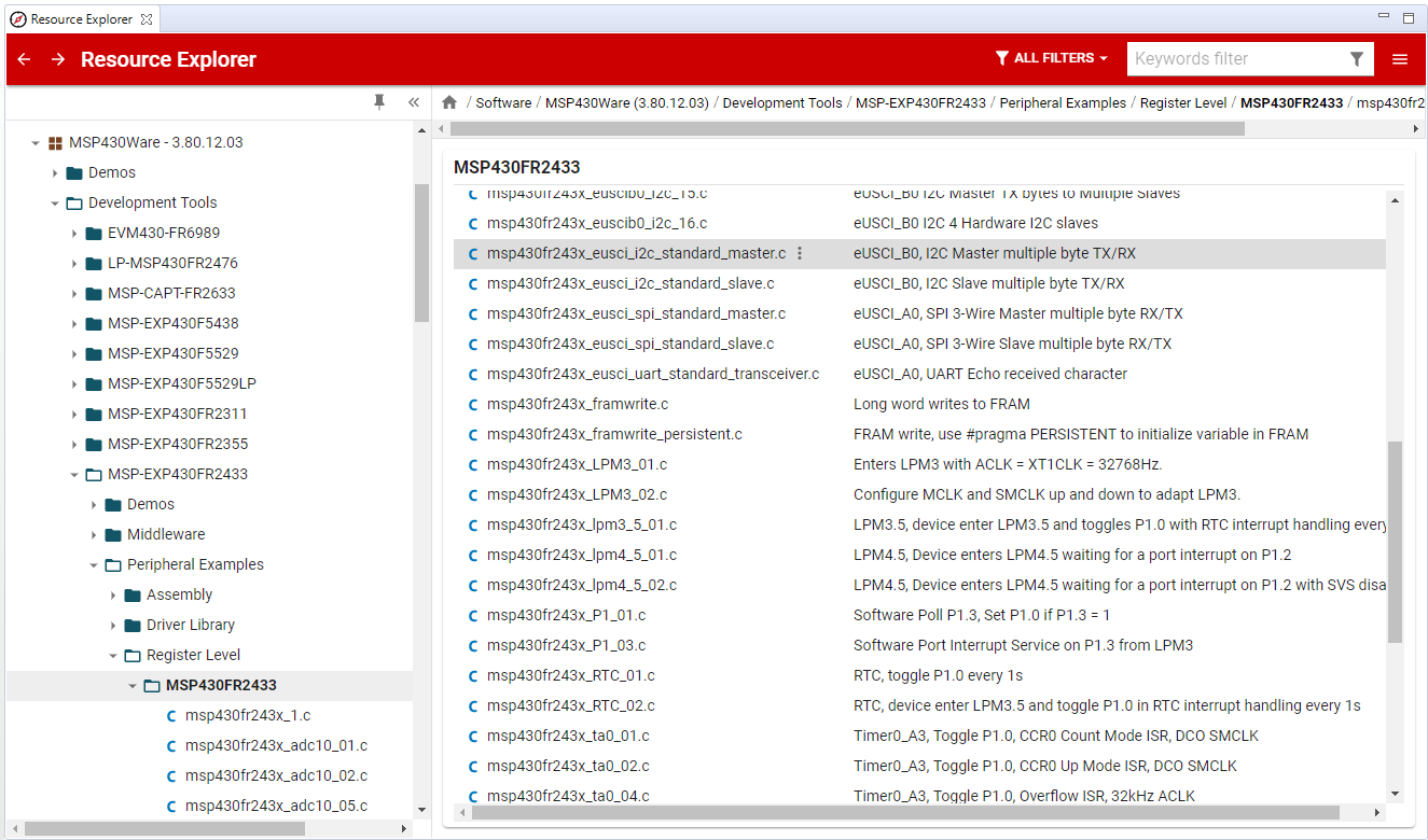
- Click Import in the upper right-hand corner
- Program the 2nd launchpad, designate this as your
I2C masterlaunchpad
Code Overview
Starting in function main(), just like the I2C slave code example, the typical housekeeping tasks, such as disabling the watchdog timer, configuring the system clocks, initializing the general-purpose input-output pins (GPIO), and configuring the I2C peripheral in master mode are performed. In addition, the I2C master code demonstrates the use of all six commands. The first three commands perform a write operation to the I2C slave with differents lengths of data. The last three commands perform read operations, requesting 3 different lengths of data.
    //******************************************************************************
    // Main ************************************************************************
    // Send and receive three messages containing the example commands *************
    //******************************************************************************

    int main(void) {
        WDTCTL = WDTPW | WDTHOLD;    // Stop watchdog timer
        initClockTo16MHz();
        initGPIO();
        initI2C();

        I2C_Master_WriteReg(SLAVE_ADDR, CMD_TYPE_0_MASTER, MasterType0, TYPE_0_LENGTH);
        I2C_Master_WriteReg(SLAVE_ADDR, CMD_TYPE_1_MASTER, MasterType1, TYPE_1_LENGTH);
        I2C_Master_WriteReg(SLAVE_ADDR, CMD_TYPE_2_MASTER, MasterType2, TYPE_2_LENGTH);

        I2C_Master_ReadReg(SLAVE_ADDR, CMD_TYPE_0_SLAVE, TYPE_0_LENGTH);
        CopyArray(ReceiveBuffer, SlaveType0, TYPE_0_LENGTH);

        I2C_Master_ReadReg(SLAVE_ADDR, CMD_TYPE_1_SLAVE, TYPE_1_LENGTH);
        CopyArray(ReceiveBuffer, SlaveType1, TYPE_1_LENGTH);

        I2C_Master_ReadReg(SLAVE_ADDR, CMD_TYPE_2_SLAVE, TYPE_2_LENGTH);
        CopyArray(ReceiveBuffer, SlaveType2, TYPE_2_LENGTH);

        __bis_SR_register(LPM0_bits + GIE);
        return 0;
    }
main()
Let's take a look at the I2C initialization steps. Before modifying any registers, always put the eUSCI module into its reset state, UCB0CTLW0=UCSWRST.
Next, configure the eUSCI module as a synchronous I2C peripheral, master mode, using the SMCLK source, UCB0CTLW0 |= UCMODE_3 | UCMST | UCSSEL__SMCLK | UCSYNC.
The SMCLK is configured for 16MHz, so we must divide it down to meet the 100kHz I2C clock requirement, UCB0BRW = 160.
The I2C slave address must be loaded with the same address that our I2C slave is using, SLAVE_ADDR = 0x48, configured by UCB0I2CSA = SLAVE_ADDR.
That's it! The eUSCI module can then be released from its reset state, UCB0CTLW0 &= ~UCSWRST.
One last thing to configure are the interrupts. Interrupts are used to notify the CPU when certain I2C events have occurred during an I2C transaction. In our code example, we want to know when if the NACK BIT' is set.
To capture this event, enable the corresponding interrupt enable bit,UCB0IE |= UCNACKIE`.
    void initI2C()
    {
        UCB0CTLW0 = UCSWRST;                      // Enable SW reset
        UCB0CTLW0 |= UCMODE_3 | UCMST | UCSSEL__SMCLK | UCSYNC; // I2C master mode, SMCLK
        UCB0BRW = 160;                            // fSCL = SMCLK/160 = ~100kHz
        UCB0I2CSA = SLAVE_ADDR;                   // Slave Address
        UCB0CTLW0 &= ~UCSWRST;                    // Clear SW reset, resume operation
        UCB0IE |= UCNACKIE;
    }
I2C Master Initialization
Next, let's take a look at the commands.
For the I2C transaction between the master device and slave device to work, both devices must have an agreement on how data is represented. In this case, the command definitions shown below are used in both the I2C slave and master code examples.
There are six command types defined; CMD_TYPE_X_MASTER and CMD_TYPE_X_SLAVE types. CMD_TYPE_X_MASTER commands represent data that the I2C master will write to the I2C slave's corresponding receive buffers. CMD_TYPE_X_SLAVE commands represent data that the I2C master will read from the I2C slave's corresponding transmit buffers. Notice that there is a different command based on the size or amount of data in the transaction. Note, these commands are completely arbitrary, but one possible use for the three CMD_TYPE_X_SLAVE commands could be used to represent the I2C slave's information such as an ID, the current time, location, or other information. For this example, the CMD_TYPE_X_SLAVE are assigned arbitrary values.
    #define SLAVE_ADDR  0x48

    /* CMD_TYPE_X_slave  is an example command the master sends to the slave.
    * The slave will send example slaveTypeX buffers in response.
    *
    * CMD_TYPE_X_MASTER  is an example command the master sends to the slave.
    * The slave will initialize itself to receive MasterTypeX example buffers.
    * */

    #define CMD_TYPE_0_slave      0
    #define CMD_TYPE_1_slave      1
    #define CMD_TYPE_2_slave      2

    #define CMD_TYPE_0_MASTER      3
    #define CMD_TYPE_1_MASTER      4
    #define CMD_TYPE_2_MASTER      5

    #define TYPE_0_LENGTH   1
    #define TYPE_1_LENGTH   2
    #define TYPE_2_LENGTH   6
I2C slave address and command definitions
When the I2C master writes data to the I2C slave, it will use one of the three MasterTypeX commands and the corresponding data buffer.
    /* MasterTypeX are example buffers initialized in the master, they will be
    * sent by the master to the slave.
    * slaveTypeX are example buffers initialized in the slave, they will be
    * sent by the slave to the master.
    * */

    uint8_t MasterType2 [TYPE_2_LENGTH] = {'F', '4', '1', '9', '2', 'B'};
    uint8_t MasterType1 [TYPE_1_LENGTH] = { 8, 9};
    uint8_t MasterType0 [TYPE_0_LENGTH] = { 11};
Master data declarations
Below is the I2C master write register function definition, which is used to write data to the I2C slave device. You can see that the function takes four arguments. The slave address specifies which device on the bus is being addressed. Next is the register address, or command, which is defined above. If, however, the I2C slave device is a sensor, these values will come from the sensor's datasheet. The last two are the data and data length.
    /* For slave device with dev_addr, writes the data specified in *reg_data
    *
    * dev_addr: The slave device address.
    *           Example: SLAVE_ADDR
    * reg_addr: The register or command to send to the slave.
    *           Example: CMD_TYPE_0_MASTER
    * *reg_data: The buffer to write
    *           Example: MasterType0
    * count: The length of *reg_data
    *           Example: TYPE_0_LENGTH
    *  */
    I2C_Mode I2C_Master_WriteReg(uint8_t dev_addr, uint8_t reg_addr, uint8_t *reg_data, uint8_t count);
I2C Master Write Register Function
Below is the I2C master read register function definition, which is used to read data from the I2C slave device. It takes three arguments. Like the I2C master write function, this function also requires a slave address to specify which device on the bus is being addressed. The register address or command comes next. Last is the length or how many bytes the I2C master will read from the I2C slave. Once the data is read, it is copied to the receive buffer array.
    /* For slave device with dev_addr, read the data specified in slaves reg_addr.
    * The received data is available in ReceiveBuffer
    *
    * dev_addr: The slave device address.
    *           Example: SLAVE_ADDR
    * reg_addr: The register or command to send to the slave.
    *           Example: CMD_TYPE_0_SLAVE
    * count: The length of data to read
    *           Example: TYPE_0_LENGTH
    *  */
    I2C_Mode I2C_Master_ReadReg(uint8_t dev_addr, uint8_t reg_addr, uint8_t count);
I2C Master Read Register Function
The I2C aster ISR handler's switch statement performs as a state machine.
    switch(__even_in_range(UCB0IV, USCI_I2C_UCBIT9IFG))
    {
      case USCI_NONE:          break;         // Vector 0: No interrupts
      case USCI_I2C_UCALIFG:   break;         // Vector 2: ALIFG
      case USCI_I2C_UCNACKIFG:                // Vector 4: NACKIFG
        break;
      case USCI_I2C_UCSTTIFG:  break;         // Vector 6: STTIFG
      case USCI_I2C_UCSTPIFG:  break;         // Vector 8: STPIFG
      case USCI_I2C_UCRXIFG3:  break;         // Vector 10: RXIFG3
      case USCI_I2C_UCTXIFG3:  break;         // Vector 12: TXIFG3
      case USCI_I2C_UCRXIFG2:  break;         // Vector 14: RXIFG2
      case USCI_I2C_UCTXIFG2:  break;         // Vector 16: TXIFG2
      case USCI_I2C_UCRXIFG1:  break;         // Vector 18: RXIFG1
      case USCI_I2C_UCTXIFG1:  break;         // Vector 20: TXIFG1
      case USCI_I2C_UCRXIFG0:                 // Vector 22: RXIFG0
          rx_val = UCB0RXBUF;
          if (RXByteCtr)
          {
            ReceiveBuffer[ReceiveIndex++] = rx_val;
            RXByteCtr--;
          }

          if (RXByteCtr == 1)
          {
            UCB0CTLW0 |= UCTXSTP;
          }
          else if (RXByteCtr == 0)
          {
            UCB0IE &= ~UCRXIE;
            MasterMode = IDLE_MODE;
            __bic_SR_register_on_exit(CPUOFF);      // Exit LPM0
          }
          break;
      case USCI_I2C_UCTXIFG0:                 // Vector 24: TXIFG0
          switch (MasterMode)
          {
            case TX_REG_ADDRESS_MODE:
                UCB0TXBUF = TransmitRegAddr;
                if (RXByteCtr)
                    MasterMode = SWITCH_TO_RX_MODE;   // Need to start receiving now
                else
                    MasterMode = TX_DATA_MODE;        // Continue to transmision with the data in Transmit Buffer
                break;

            case SWITCH_TO_RX_MODE:
                UCB0IE |= UCRXIE;              // Enable RX interrupt
                UCB0IE &= ~UCTXIE;             // Disable TX interrupt
                UCB0CTLW0 &= ~UCTR;            // Switch to receiver
                MasterMode = RX_DATA_MODE;    // State state is to receive data
                UCB0CTLW0 |= UCTXSTT;          // Send repeated start
                if (RXByteCtr == 1)
                {
                    //Must send stop since this is the N-1 byte
                    while((UCB0CTLW0 & UCTXSTT));
                    UCB0CTLW0 |= UCTXSTP;      // Send stop condition
                }
                break;

            case TX_DATA_MODE:
                if (TXByteCtr)
                {
                    UCB0TXBUF = TransmitBuffer[TransmitIndex++];
                    TXByteCtr--;
                }
                else
                {
                    //Done with transmission
                    UCB0CTLW0 |= UCTXSTP;     // Send stop condition
                    MasterMode = IDLE_MODE;
                    UCB0IE &= ~UCTXIE;                       // disable TX interrupt
                    __bic_SR_register_on_exit(CPUOFF);      // Exit LPM0
                }
                break;

            default:
                __no_operation();
                break;
          }
          break;
      default: break;
    }
I2C Master ISR Hander and State Machine
Logic Probe Captures
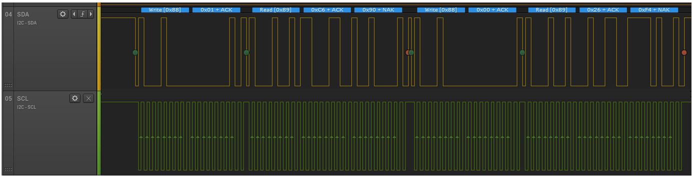
Once you have the device programmed, reset the I2C slave LaunchPad to ensure it is in a state to initiate communications by briefly pressing the RESET button on the launchpad near the USB connector, then do the same on the I2C master LaunchPad.
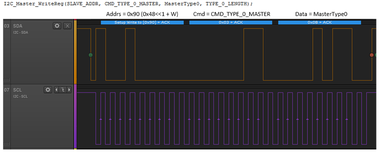
The capture shown here is the first write operation that the I2C master device performs.
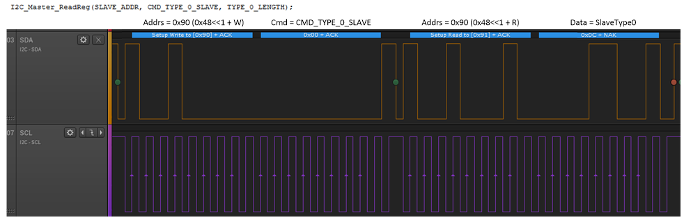
The next capture shows the first read operation that the I2C master performs.
Other operations are performed for the other two data types.
Task 3 – Modify I2C master example to read sensor
In this task, you will build upon a few of the things you learned/discovered in the previous sections and modify the I2C master code to communicate with the OPT3001 optical Sensor on the BOOSTXL-BASSENSORS BoosterPack. Don't worry about where to start. We will guide you through the steps.
The BoosterPack Module has a variety of sensors. In this lab, you will be using the OPT3001 optical sensor. This sensor is operated over the I2C bus with registers that contain configuration, status, and result information.
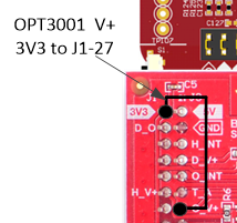
Note, before using the OPT3001 sensor you will need to install a jumper from +3v3 to J1-27 on the BoosterPack to provide power for the OPT3001 sensor
To communicate with the OPT3001 you will need to know a couple of things:
- What is the sensor's I2C address
- How to configure the sensor to make it work
Which sensor register does the master read and how many bytes
To help answer these questions you will need to reference the following documentation:
Open the datasheet and locate the I2C device address and register tables
- Open the BoosterPack's user guide and check the schematic to see how the address pin is configured.
Software Modifications
The OPT3001 sensor's I2C address is described in the sensor's datasheet. Hint, you will find your answer in the BoosterPack documentation. Modify the line of code where the SLAVE_ADDR is currently defined as #define SLAVE_ADDR 0x48
What is the OPT3001 I2C slave address?
Redefine the slave address.
    //#define SLAVE_ADDR  0x48
    #define SLAVE_ADDR  0x44
Before the I2C master can start communicating with the OPT3001 sensor, the sensor must first be initialized by writing a configuration value to the sensor's configuration register using the I2C_Master_WriteReg() function call.
You will need to dig into the datasheet to see what configuration value is needed. As a note, some sensors don't require this step.
After the sensor starts working, you will use the I2C_Master_ReadReg() function call to retrieve the light data.
So here is where you need to determine the appropriate configuration value. A hint is, you want the sensor to perform continuous conversions. Look at the default values in the configuration register table and modify the appropriate bits.
What value is required to configure the sensor to perform continuous conversions?
Next, you need to populate the MasterType1 data array with the 2 bytes that represent the sensor's 16-bit configuration register value.
Here is a working example.
    //uint8_t MasterType1 [TYPE_1_LENGTH] = {8, 9};
    uint8_t MasterType1 [TYPE_1_LENGTH] = { 0xCE, 0x10};
At this point, you know the sensor's I2C address, the sensor configuration value and you have prepared the MasterType1 data array.
You can now modify the function call I2C_Master_WriteReg() with the appropriate arguments.
Here is a working example.
I2C_Master_WriteReg(SLAVE_ADDR, 0x01, MasterType1, TYPE_1_LENGTH);
The last step is to construct the I2C_Master_ReadReg() function call and use the CopyArray() functions.
Here, you need to figure out which sensor register to read the data from and how many bytes to read. It should be obvious from the register map table in the sensor's datasheet that the conversion results are stored in the sensor's Result register.
What is the register address where the conversion results are stored and how many bytes do you read?
Knowing the sensor's result register and the number of bytes to be read, you can construct the I2C_Master_ReadReg() function call with the appropriate arguments.
But don't forget, you also need to construct the CopyArray() function, which includes your receive buffer (where the results will be stored), the SlaveTypeN command, and the number of bytes.
Here is a working example.
    I2C_Master_ReadReg(SLAVE_ADDR, 0x00, TYPE_1_LENGTH);
    CopyArray(ReceiveBuffer, SlaveType1, TYPE_1_LENGTH);
Last, add a while-loop so you can continuously read the OPT3001 sensor and copy the results into the receive buffer. The sensor is configured to perform a conversion every 100msec, so add a delay to reduce the amount of time the CPU spends polling.
Here is a working example.
Adding a watch expression to the expression view allows you to inspect the value in SlaveType1.
To verify the measurements change with varying light conditions, add a __no_operation() just after the CopyArray() function call then try covering the sensor or shining a bright light to see the sensor's range of sensitivity.
This provides a convenient location to place a debugger breakpoint. Build and program the code and start the debugger. The program counter will stop at the breakpoint.
If you have a logic analyzer available and you captured the transaction does it look like this?
Hopefully, you had success to get everything to work. If not, here are a couple of things to try.
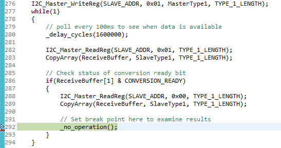
Here is the complete solution.
    int main(void) {
        WDTCTL = WDTPW | WDTHOLD;    // Stop watchdog timer
        initClockTo16MHz();
        initGPIO();
        initI2C();

        I2C_Master_WriteReg(SLAVE_ADDR, 0x01, MasterType1, TYPE_1_LENGTH);
        while(1)
        {
            // poll every 100ms to see when data is available
            _delay_cycles(1600000);

            I2C_Master_ReadReg(SLAVE_ADDR, 0x01, TYPE_1_LENGTH);
            CopyArray(ReceiveBuffer, SlaveType1, TYPE_1_LENGTH);

            // Check status of conversion ready bit
            if(ReceiveBuffer[1] & CONVERSION_READY)
            {
                I2C_Master_ReadReg(SLAVE_ADDR, 0x00, TYPE_1_LENGTH);
                CopyArray(ReceiveBuffer, SlaveType1, TYPE_1_LENGTH);

                // Set break point here to examine results
                _no_operation();
            }
        }
    }
Did you installed a jumper from +3v3 to J1-27 on the BoosterPack to provide power for the OPT3001 sensor
Task 4 – Modify I2C slave example to emulate a sensor
In the previous task, you modified the master I2C code example to work with the OPT3001 sensor, so by now, you should feel pretty comfortable creating I2C master code that communicates with most any I2C slave devices.
In this lab, you are going to modify the I2C slave code so it behaves like the OPT3001. You only need to support the I2C master writing and reading a configuration register, and reading from a results register.
This can be done easily by modifying the #defines for the master and slave I2C.
Important
For this to work, you must remove the one jumper from the BoosterPack that provides power to the OPT3001 sensor, else there will be two I2C slaves on the bus with the same address.
Master Software Modifications
You are going to have to re-vist the I2C master code example and make a few changes, such as, adding a new set of definitions mapped uniquely for the emulated sensor.
NOTE:
To support both the real sensor and emulated sensor, use SENSOR_TYPE==SENSOR_MSP_SLAVE when the I2C slave LaunchPad is the sensor, and SENSOR_TYPE==SENSOR_OPT3001 when using the real OPT3001 sensor.
    #define SENSOR_OPT_3001         0
    #define SENSOR_MSP_SLAVE        1

    #define SENSOR_TYPE             (SENSOR_MSP_SLAVE)  // change this

    #define SLAVE_ADDR              0x44
    #define CONVERSION_READY        0x10
    #define MAX_BUFFER_SIZE         20

    #if SENSOR_TYPE==SENSOR_MSP_SLAVE

    #define CMD_TYPE_0_SLAVE        0
    #define CMD_TYPE_1_SLAVE        1
    #define CMD_TYPE_2_SLAVE        2

    #define CMD_TYPE_0_MASTER       3
    #define CMD_TYPE_1_MASTER       4
    #define CMD_TYPE_2_MASTER       5

    #define TYPE_0_LENGTH           1
    #define TYPE_1_LENGTH           2
    #define TYPE_2_LENGTH           6

    // Add the following:
    #define READ_RESULT_REGISTER    (0)
    #define WRITE_CONFIG_REGISTER   (1)
    #define READ_CONFIG_REGISTER    (1)

    #else

    #define CMD_TYPE_0_SLAVE        0
    #define CMD_TYPE_1_SLAVE        1
    #define CMD_TYPE_2_SLAVE        2

    #define CMD_TYPE_0_MASTER       3
    #define CMD_TYPE_1_MASTER       4
    #define CMD_TYPE_2_MASTER       5

    #define TYPE_0_LENGTH           1
    #define TYPE_1_LENGTH           2
    #define TYPE_2_LENGTH           6

    // Add the following:
    #define READ_RESULT_REGISTER  (CMD_TYPE_0_SLAVE)
    #define WRITE_CONFIG_REGISTER (CMD_TYPE_1_MASTER)
    #define READ_CONFIG_REGISTER  (CMD_TYPE_1_SLAVE)

    #endif
Conditional #defines
Next, you are going to use MasterType1 to store the sensor's 16-bit configuration value {0xC6, 0x00} and send to the real or emulated sensor when it's time to configure it.
    /* MasterTypeX are example buffers initialized in the master, they will be
    * sent by the master to the slave.
    * SlaveTypeX are example buffers initialized in the slave, they will be
    * sent by the slave to the master.
    * */

    uint8_t MasterType2 [TYPE_2_LENGTH] = {0,0,0,0,0,0};
    uint8_t MasterType1 [TYPE_1_LENGTH] = {0xC6, 0x00};
    uint8_t MasterType0 [TYPE_0_LENGTH] = {0};

    uint8_t SlaveType2 [TYPE_2_LENGTH] = {0};
    uint8_t SlaveType1 [TYPE_1_LENGTH] = {0};
    uint8_t SlaveType0 [TYPE_0_LENGTH] = {0};
Data Arrays
In main, substitute the new #defines for the hard coded register values used in the previous task.
    int main(void) {
        WDTCTL = WDTPW | WDTHOLD;    // Stop watchdog timer
        initClockTo16MHz();
        initGPIO();
        initI2C();

        I2C_Master_WriteReg(SLAVE_ADDR, WRITE_CONFIG_REGISTER, MasterType1, TYPE_1_LENGTH);
        while(1)
        {
            // poll every 100ms to see when data is available
            _delay_cycles(1600000);

            I2C_Master_ReadReg(SLAVE_ADDR, READ_CONFIG_REGISTER, TYPE_1_LENGTH);
            CopyArray(ReceiveBuffer, SlaveType1, TYPE_1_LENGTH);

            // Check status of conversion ready bit
            if(ReceiveBuffer[1] & CONVERSION_READY)
            {
                I2C_Master_ReadReg(SLAVE_ADDR, READ_RESULT_REGISTER, TYPE_1_LENGTH);
                CopyArray(ReceiveBuffer, SlaveType1, TYPE_1_LENGTH);

                // Set break point here to examine results
                _no_operation();
            }
        }
    }
Main()
Slave Software Modifications
On the I2C slave, modify the SlaveType1 with a value that would appear in the real sensor's configuration when data is available. Also, modify SlaveType0 to hold the dummy result. Notice how all the commands (registers) are defined as the same length, TYPE_1_LENGTH.
   uint8_t MasterType1 [TYPE_1_LENGTH] = {0,0};  // Emulates OPT3001 Configuration register
   uint8_t MasterType0 [TYPE_1_LENGTH] = {0,0};

   uint8_t SlaveType1 [TYPE_1_LENGTH] = {0xCE,CONVERSION_READY};  // Emulates OPT3001 Configuration register
   uint8_t SlaveType0 [TYPE_1_LENGTH] = {0xAA, 0x55};  // A dummy measurement
And don't forget,in the I2C slave code, you need to change the slave address from 0x48 to 0x44, which is the OPT3001 slave address.
    // Emulate the OPT3001 - slave address is 0x44
    #define SLAVE_ADDR          0x44
    #define CONVERSION_READY    0x10
Emulated Sensor Slave Address
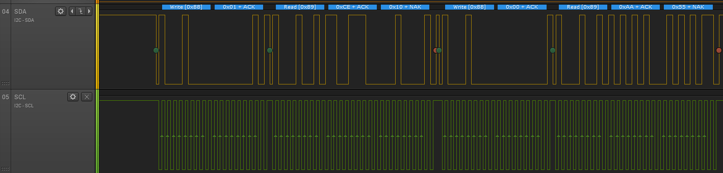
You can see in the I2C transaction that the emulated sensor returns 0xCE, 0x10 when the master I2C polls for new data, then it reads the dummy results 0xAA, 0x55.
Summary
At the end of this lab, you should know:
- The Fundametals of I2C read and write transactions
- How to use MSP430 as I2C master to read data from a sensor
- How to use MSP430 as I2C slave to emulate a sensor
This work is licensed under a Creative Commons Attribution-NonCommercial-NoDerivatives 4.0 International License.