Introduction
This lab introduces the Universal asynchronous receiver-transmitter (UART). It demonstrates implementing UART communication using the MSP-EXP430FR2433 and its integrated enhanced Universal Serial Communication Interface (eUSCI) module in UART mode which can be used in applications requiring serial communications with other microcontrollers (MCUs) or a PC.
This lab uses register level code examples from MSP430Ware and has 3 tasks consisting of the following activities:
- Setup MCU in loopback mode (fundamentals of configuring the registers)
- Setup MCU to echo characters from a PC (basic communication with PC, modify baud rate)
- Create functional UART transceiver (MCU responds with message to terminal application on PC)
Prerequisites
Hardware
The following hardware is required for this lab
Optional but recommended to help with understanding UART communication
- Logic analyzer
Software
- Code Composer Studio (CCS)
- MSP430FR2433 Code Examples
- Any RS232 Terminal console application
Installing the software
NOTE:
These software examples used in this lab should be imported from within the TI Resource Explorer. This can be accessed from the web or within CCS by clicking View→Resource Explorer. To access TI Resource Explorer to import the examples into the Code Composer Studio (CCS) IDE, MSP430Ware must be installed on your PC. This may be done when CCS was installed or can be done later by clicking the "Download and Install" icon in the top right. Note that installing MSP430Ware for any project will install ALL labs and content, so this only needs to be done once.
Recommended Resources
The documentation can be referenced for the MSP430 MCU and the LaunchPad details.
- MSP430FR2433 MCU Datasheet
- MSP430FR4xx and MSP430FR2xx Family User's Guide
- MSP430 MCUs Development Guide Book
- Solutions to Common eUSCI and USCI Serial Communication Issues on MSP430 MCUs
Overview
This lab introduces fundamental UART functionality on MSP MCUs. Only the UART initialization, operation and interrupt handling portion of the code examples are the focus of this training academy. Other portions of the code example related to the MCU's clock and GPIO initialization are presented for context and are left up to the reader to investigate separately through topic-specific TI Academy trainings.
In this lab, you will be using an MSP430FR2433 LaunchPad. One of the MSP430FR2433 UART peripherals is connected to the LaunchPad's programmer/debugger backchannel UART, which provides a virtual serial port connection to the PC. This makes it possible to send and receive bytes with no additional hardware required.
Getting Started
Hardware Setup:
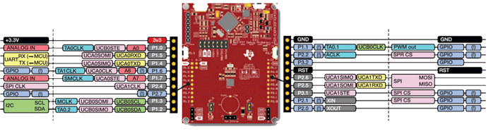
LaunchPad BoosterPack Pinout
Task 1 – Loop-Back
Example Project Overview
This first project starts with the fundamentals of configuring a UART at the register level and demonstrates how to send and receive a byte using a loopback method of connecting the UART's TX to RX with a jumper. The example code shows proper initialization of registers and interrupts to receive and transmit data.
In this task, there is no code to modify, so build and program the MSP430 LaunchPad with the UART loopback example code.
- Import the UART example msp430fr243x_euscia0_uart3.c into CCS from TI Resource Explorer.
MSP430Ware→Development Tools→MSP-EXP430FR2433→Peripheral Examples→Register Level→MSP430FR2433→
msp430fr243x_euscia0_uart3.c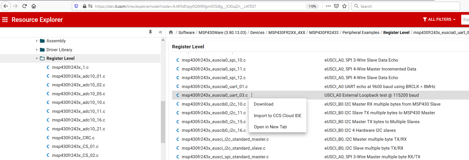
- Click Import in the upper right hand corner
- Program the LaunchPad.
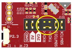
- Remove the MSP430FR2433 LaunchPad TXD and RXD jumpers from J101. Use one of the jumpers to short across the TXD and RXD on the pins closest to the MCU.
Code Overview
Let's take a look at the UART initialization code. This example uses 115200 baud. Baud is the UART's bit rate and is sourced from the MSP system clock (SMCLK) running at 1MHz. This 1MHz clock must be divided down to create the 115200 Baud clock. There is a formula in the MSP430FR2433 User's Guide that describes how to calculate the specific UART register values. For convenience, there is also a TI baud rate calculator on the web. After setting up the baud rate, the UART module is enabled and its receive interrupt is enabled.
    // Configure UART
    UCA0CTLW0 |= UCSWRST;                     // Put eUSCI in reset
    UCA0CTLW0 |= UCSSEL__SMCLK;
    // Baud Rate calculation
    UCA0BR0 = 8;                              // 1000000/115200 = 8.68
    UCA0MCTLW = 0xD600;                       // 1000000/115200 - INT(1000000/115200)=0.68
                                              // UCBRSx value = 0xD6 (See UG)
    UCA0BR1 = 0;
    UCA0CTLW0 &= ~UCSWRST;                    // Initialize eUSCI
    UCA0IE |= UCRXIE;                         // Enable USCI_A0 RX interrupt
The next portion of the example code is a while-loop, whereupon entering for the first time, data is loaded into the UART's transmit buffer causing the byte to immediately be clocked out of the UART's TXD pin. The CPU will then enter its low-power mode 0, which stops the CPU but allows the system clocks and UART to remain active. The CPU remains in low-power mode 0 until the receive interrupt is generated by the received byte.
    while (1)
    {
        while(!(UCA0IFG & UCTXIFG));
        UCA0TXBUF = TXData;                   // Load data onto buffer

        __bis_SR_register(LPM0_bits|GIE);     // Enter LPM0
        __no_operation();                     // For debugger
    }
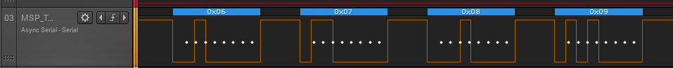
Since the TXD and RXD pins on the MSP430FR2433 LaunchPad are connected, the transmitted byte appears in the UART's receive buffer which generates a receive interrupt. If you have a logic probe handy, can connect it to the jumper that is connecting the TXD and RXD pins. You should see something similar to this capture.
The interrupt service routine (ISR) handler (shown below) uses a switch statement that selects the appropriate code section of the ISR to execute based on the interrupt vector value. In the receive portion of the ISR, the captured byte is stored in a local variable. A match is performed to check that the byte value sent is the same as the one received.
       switch(__even_in_range(UCA0IV,USCI_UART_UCTXCPTIFG))
        {
            case USCI_NONE: break;
            case USCI_UART_UCRXIFG:
                  UCA0IFG &=~ UCRXIFG;            // Clear interrupt
                  RXData = UCA0RXBUF;             // Clear buffer
                  if(RXData != TXData)            // Check value
                  {
                      P1OUT |= BIT0;              // If incorrect turn on P1.0
                      while(1);                   // trap CPU
                  }
                  TXData++;                             // increment data byte
                  __bic_SR_register_on_exit(LPM0_bits); // Exit LPM0 on reti
                  break;
            case USCI_UART_UCTXIFG: break;
            case USCI_UART_UCSTTIFG: break;
            case USCI_UART_UCTXCPTIFG: break;
        }
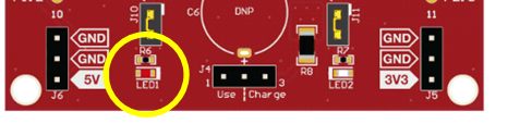
If the values don't match, the code enters a "forever" while-loop and turns on an LED P1.0 on the LaunchPad. If the values do match another variable is used to keep track of the number of bytes received.
To check your understanding so far, let's take a quick quiz.
In the example provided, what clock source in the MSP was selected to provide the bit rate clock for the UART?
Task 2 – Echo Characters
Example Project Overview
In this task, the code example demonstrates how to echo characters received from the PC. The MSP430FR2433 will communicate with a PC connected to the LaunchPad through the LaunchPad's back-channel UART. The code example is complete and operates at 9600 baud. Once you get the example code working with your PC, your goal will be to reconfigure the baud rate to 19200 baud. This may take some trial and error but once you have it working successfully then you will have a tested and working serial communication link to your PC. This link will be needed in the next task that follows.
Import the UART code example msp430fr243x_euscia0_uart_01.c from Resource Explorer.
MSP430ware→Development Tools→MSP-EXP430FR2433→Peripheral Examples→Register Level→MSP430FR2433→
msp430fr243x_euscia0_uart_01.c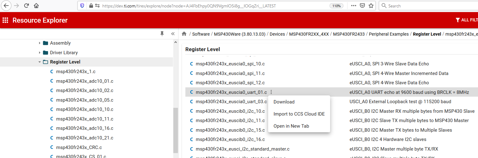
- Click import in the upper right hand corner
Re-install the MSP430FR2433 LaunchPad TXD and RXD jumpers on J101.
Connect the LaunchPad to the PC using the USB cable and program the LaunchPad.
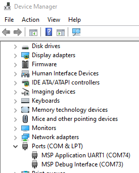
Determine which serial COM port has enumerated as the "MSP Application UART" port by launching the Windows device manager. Open the “Run” dialog box by pressing and holding the Windows key, then press the R key (“Run”). Type devmgmt.msc. Click OK.
Configure your terminal application accordingly. Here is a snapshot of Termite.
Note, if your terminal application has a setting for "local echo" you want to disable it.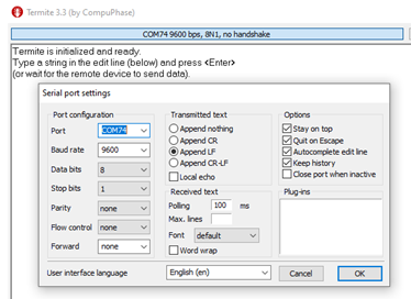
Important: When running this demo example or any demo while in debug mode and using the LaunchPad's back-channel UART, there can be a delay in response from the MSP430 to the PC. It is highly recommended to run this demo with the debugger disabled.
Code Overview
In this example, the MSP system clock (SMCLK) is configured to run at 8MHz.. The UART has been configured to operate at 9600 baud as shown below.
    // Configure UART
    UCA0CTLW0 |= UCSWRST;
    UCA0CTLW0 |= UCSSEL__SMCLK;

    // Baud Rate calculation
    // 8000000/(16*9600) = 52.083
    // Fractional portion = 0.083
    // User's Guide Table 14-4: UCBRSx = 0x49
    // UCBRFx = int ( (52.083-52)*16) = 1
    UCA0BR0 = 52;                             // 8000000/16/9600
    UCA0BR1 = 0x00;
    UCA0MCTLW = 0x4900 | UCOS16 | UCBRF_1;

    UCA0CTLW0 &= ~UCSWRST;                    // Initialize eUSCI
    UCA0IE |= UCRXIE;                         // Enable USCI_A0 RX interrupt
main()
On your PC, type a character on the keyboard. You should see the same character echoed back to the screen. If not, check your connections and serial terminal configuration settings.
Here is how the example code works. When the 8-bit character from the PC appears in the UART's receive buffer, it generates a receive interrupt. The ISR (shown below) uses a switch statement that selects the appropriate code section of the ISR to execute based on the interrupt vector value. In the receive portion of the ISR, the captured byte is read from the UART's UCA0RXBUF and placed into the UCA0TXBUF, which immediately triggers the UART to transmit the character back to the PC.
      switch(__even_in_range(UCA0IV,USCI_UART_UCTXCPTIFG))
  {
    case USCI_NONE: break;
    case USCI_UART_UCRXIFG:
      while(!(UCA0IFG&UCTXIFG));
      UCA0TXBUF = UCA0RXBUF;
      __no_operation();
      break;
    case USCI_UART_UCTXIFG: break;
    case USCI_UART_UCSTTIFG: break;
    case USCI_UART_UCTXCPTIFG: break;
    default: break;
  }
The goal is to change the baud rate to operate at 19200 baud. Please refer to Section 22.3.10 in the following user's guide.
If you are not able to get the 19200 baud rate to work properly, compare your values to TI's on-line baud rate calculator. Be sure you select the EUSCI option. Also, don't forget to update your PC terminal configuration to 19200 baud as well. Test the new baud rate by typing a few characters on the keyboard.
Hopefully, you were successful in getting everything to work. If not, try this.
Here is a working example.
        UCA0BR0 = 26;
        UCA0BR1 = 0x00;
        UCA0MCTLW = 0xD600 | UCOS16 | UCBRF_0;
Task 3 – Transceiver
In this portion of the lab, you will build on what you learned in the last task by adding additional code to the UART's ISR allowing it to respond to the PC with an acknowledgment message. The code should test each received byte and compare if the value is either 0x0A (10 decimal) or 0x0D (13 decimal), which are the American Standard Code for Infomation Interchange (ASCII) byte values for a carriage return (CR) and linefeed (LF) characters used to signal the end of a group of transmitted bytes. For more information about ASCII, search the web for "ASCII" or "ASCII table" to view a convenient table of characters.
There are 2 actions that need to be performed:
- Add receive buffer and logic for receiving bytes from the PC
- Add transmit buffer and logic to send the acknowledgment message
Software Modifications
Receive Buffer
A receive buffer is used to temporarily store each byte received from the PC. You will need to create a byte buffer of reasonable size. This example uses 32 bytes.
Transmit Buffer
The transmit buffer in this example will be a fixed size, based on the length of the message. For this example, we use text "ok\n" to initialize the transmit buffer. The "\n" represents the ASCII newline character byte that signals to the PC our end of message.
Here is a hint showing the buffer implementation.
    char RXbuffer[32];
    const unsigned char maxRXbytes = sizeof(RXbuffer);
    unsigned char RXbytes = 0;

    const char message[] = "ok\n";
    const unsigned char messageLength = sizeof(message);
    unsigned char TXbytes = 0;
Receive Logic
When you type something on the PC's keyboard, such as "hello world" then hit the ENTER key, these characters will be received by the UART's hardware receive buffer and generate a receive interrupt. Your task is to examine each byte looking for the ASCII newline character, 0x0A. If the received byte is not 0x0A, then you store the byte in your receive buffer and wait for the next byte to be received. When the newline byte is detected, your code should respond to the PC with a message "ok" followed by the newline character 0x0A to indicate to the PC the end of your message. If you have the message buffer set up properly, all you should have to do is enable the transmit interrupt and the rest is handled by the transmit logic code you will add to the transmit portion of the UART ISR.
You will also need to manage the buffer's contents. This means when the newline byte is received you need to reset your receive buffer to make the buffer ready to receive the next sequence of bytes, else you run the risk of overflowing the allocated storage and writing the new bytes into memory locations beyond the buffer and potentially causing erratic program behavior.
Transmit Logic
When the 0x0A byte is received from the PC, you will send the first byte of the acknowledgment message, followed by the next, and repeat until all the bytes in the transmit buffer has been sent. You will add transmit logic to the transmit section of the UART ISR that loads the UART's hardware transmit buffer with each byte until your message is sent. When the last byte is loaded into the UART's transmit buffer, don't forget to disable the transmit interrupt and reset your transmit logic so it is ready to send the message again when the PC sends the sequence of bytes, else the UART will continue to generate transmit interrupts and send random bytes to the PC. .
Here is a working example for the switch-case statement.
       switch(__even_in_range(UCA0IV,USCI_UART_UCTXCPTIFG))
       {
         case USCI_NONE: break;
         case USCI_UART_UCRXIFG:

             if(RXbytes < maxRXbytes)
             {
                 // Get the byte
                 RXbuffer[RXbytes] = UCA0RXBUF;

                 // Check for either ASCII carriage return '\r', or linefeed '\n' character.
                 // If true enable the TX interrupt to send response message
                 if((RXbuffer[RXbytes] == '\r') || (RXbuffer[RXbytes] ==  '\n'))
                 {
                     // Start message transmission
                     UCA0IE |= UCTXIE;

                     // Reset receive buffer index
                     RXbytes = 0;
                 }
                 else
                     RXbytes++;

             }
             break;

         case USCI_UART_UCTXIFG:

             // Transmit the byte
             UCA0TXBUF = message[TXbytes++];

             // If last byte sent, disable the interrupt
             if(TXbytes == messageLength)
             {
                 UCA0IE &= ~UCTXIE;
                 TXbytes = 0;
             }
             break;

         case USCI_UART_UCSTTIFG: break;
         case USCI_UART_UCTXCPTIFG: break;
         default: break;
       }
To check your understanding so far, let's take a quick quiz.
In this task, why is it important to disable the transmit interrupt after all the acknowledgment message bytes have been transmitted?
Perform Some Useful Action
Now that you have a simple working transceiver, how can it be made more useful? One feature to add is a way to parse or check the bytes sent from PC or other MCU, looking for a specific sequence of bytes that would represent a command and parameter value. Based on this command and parameter, you could turn on or off an LED on the LaunchPad. Since you have done part of this work already, by capturing the received bytes in your receive buffer, all you need is some code to search through these bytes to find the command and parameter. Your code should search for the following ASCII bytes: "L", "1", and if found, turn on LED1. When the ASCII bytes "L", "0" are received, you turn off LED1. Can you manage to do this all in the ISR? Refer to an ASCII table to determine the required values.
The letter "L" has as an ASCII value 0x4C (76 decimal), "1" has an ASCII value 0x31 (49 decimal), and "0" has an ASCII value 0x30 (48 decimal).
Here is a working example for the switch-case statement.
       switch(__even_in_range(UCA0IV,USCI_UART_UCTXCPTIFG))
       {
         case USCI_NONE: break;
         case USCI_UART_UCRXIFG:

             if(RXbytes < maxRXbytes)
             {
                 // Get the byte
                 RXbuffer[RXbytes] = UCA0RXBUF;

                 // Check for either ASCII carriage return '\r', or linefeed '\n' character.
                 // If true enable the TX interrupt to send response message
                 if((RXbuffer[RXbytes] == '\r') || (RXbuffer[RXbytes] ==  '\n'))
                 {
                     // Start message transmission
                     UCA0IE |= UCTXIE;

                     // Parse the command and parameter
                     if((RXbuffer[0] == 'L') && (RXbuffer[1] == '0'))
                     {
                         P1OUT &= ~BIT0;
                     }
                     else if((RXbuffer[0] == 'L') && (RXbuffer[1] == '1'))
                     {
                         P1OUT |= BIT0;
                     }

                     // Reset receive buffer index
                     RXbytes = 0;
                 }
                 else
                     RXbytes++;
            }

           __no_operation();
           break;
         case USCI_UART_UCTXIFG:

             // Transmit the byte
             UCA0TXBUF = message[TXbytes++];

             // If last byte sent, disable the interrupt
             if(TXbytes == messageLength)
             {
                 UCA0IE &= ~UCTXIE;
                 TXbytes = 0;
             }

             __no_operation();
             break;
         case USCI_UART_UCSTTIFG: break;
         case USCI_UART_UCTXCPTIFG: break;
         default: break;
       }
Challenge
Congratulations on making it to the end! Now, if you are up to the challenge, think about how you might send one message to the PC when your turn the LED on and a different message when you turn the LED off?
Summary
At the end of this lab, you should now be able to:
- Have a fundamental understanding how the a UART transmits and receives bytes
- Familiar with handling UART interrupt events
- Re-configure baud rates
- Make a working transceiver
This work is licensed under a Creative Commons Attribution-NonCommercial-NoDerivatives 4.0 International License.