Introduction
TI 15.4-Stack is an IEEE 802.15.4e/g RF communication stack. It is a main part of the SimpleLink CC13x2_CC26x2 Software Development Kits (SDK), and provides support for star-topology networks for a Sub-1GHz application or a 2.4GHz application, depending on your selected device. TI 15.4-Stack runs on MCUs from TI's SimpleLink microcontroller (MCU) family of devices. The Sub-1 GHz implementation offers several key benefits such as longer range in FCC band and better protection against in-band interference by implementing frequency hopping, as well as the ability to send 2.4GHz BLE beacon packets while operating on a Sub-1GHz TI 15.4-Stack network when using dual-band mode on the CC1352. This complete stack offering provides customers an accelerated time to market with a complete end-to-end node-to-gateway solution.
In this lab, we will go through the necessary steps to add a generic sensor to the Collector/Sensor Applications. The purpose of this lab is to familiarize the users with the application parts of the TI 15.4-Stack. The lab contains several tasks:
Task 1: Building and loading the collector example with new generic functionality
Task 2: Building and loading the sensor example with new generic functionality
Task 3: Using the Collector and Sensor
Further reading
This lab is the recommended first step for getting started with changing up your sensors, it is intended to teach you to quickly create a variety of sensors. As such, many useful features in TI 15.4-Stack are not discussed here. To learn more about features such as beacon vs. non-beacon mode, frequency hopping and more, please see the TI 15.4 Stack User Guide, under the SDK installation folder.
Technical support
For any questions you may have, please consult the relevant E2E forum - TI Sub-1 GHz E2E Forum
Supported Devices/SDKs
This lab is intended to be used with the newest SDKs for each of these TI devices:
| TI Device | SDK |
|---|---|
| CC13x0 | SIMPLELINK-CC13X0-SDK |
| CC13x2 & CC26x2 | SIMPLELINK-CC13X2-26X2-SDK |
Prerequisites
Background
- Basic TI-RTOS and CCS knowledge
- Some basic familiarity with embedded programming
Software
- Code Composer Studio v9.2 or later
Make sure that CCS is using the latest updates: Help → Check for Updates - The corresponding SDK(s) from the list above
- Tera term or any other equivalent terminal program
Hardware
- 2 x Compatible LaunchPads, refer to the Supported Devices/SDKs section
- 2 x USB Cables
Using the Generic Sensor functionality
- The generic sensor will send a value that corresponds to the number of times BTN-1 on the Sensor Launchpad is pressed. (each time BTN-1 is pressed, the generic sensor value is incremented)
Note
- These labs were done using CC13x2 LaunchPads and the CC13x2_CC26x2 SDK, though the procedure should be the same for every supported platform.
- Some screenshots in this lab may have been taken with an older version of the respective SDK or tool, so your actual screen may look a bit different, however the functionality and overall look and feel should be the same.
Group training additional requirements
Make sure to always use your designated channel, to avoid interfering with other students' operations
Channel allocation
If you are part of a group training, the instructor should give each student a unique channel number. In this lab, each student uses a designated channel matching its student number: Student #1 should use channel 1, Student #2 should use channel 2, and so on.
Task 0: Label your LaunchPads
Label each of your LaunchPads with its XDS Device ID, as described here.
Additionally, label one LaunchPad as "Sensor" and the other as "Collector". These labels will be referred to throughout this lab. It is recommended to use a non-permanent marking for this (e.g. sticky notes), as these labels may only be relevant for this specific lab.
Task 1: Building and loading the collector example with new generic functionality
Collector Overview
In this task, you will:
- Learn about the type of sensor messages that the collector can receive
- Learn how to add a new type of sensor message for the collector to receive
- Learn how to set the sensors to poll at different intervals
- Learn how the collector processes sensor data
- Learn how to send requests from the collector to sensors
- Learn about the CUI (Common User Interface) and how to add a new status line
Collector Implementation
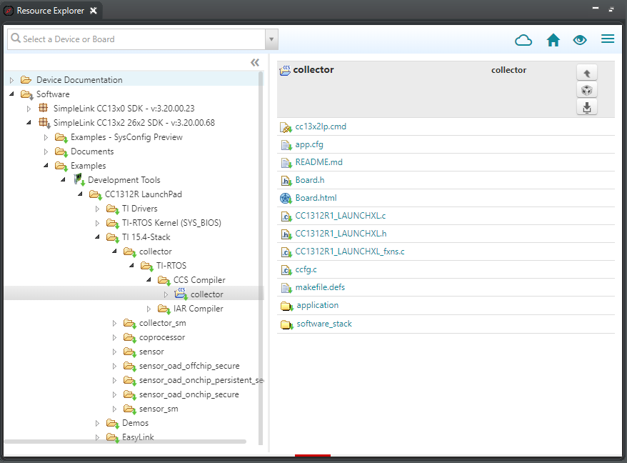
In CCS, open the resource explorer (view → Resource Explorer)
Expand the folders and select as in the following capture, then click Import To IDE: (Note: make sure to select the appropriate collector project for your platform. e.g. if you are using CC2652, select the CC2652 collector project in the CC26x2 SDK)
Update the target of the collector project to associate it with the "Collector" LaunchPad - as explained here.
Edit smsgs.h
In this file, you will be adding new message types that the collector and
sensors can receive. smsgs.h is a header file that contains defines and
variable declarations that are used by the sensor and collector to both build
and parse sensor related messages. We will be updating and adding to this file
so that our devices can build and parse our new generic sensor data messages.
Open the file:
collector_YOURBOARD_LAUNCHXL_tirtos_ccs/application/collector/smsgs.hAdd in the generic sensor definitions. These defines will allow the collector and sensor to know the length of the Generic message types. Let's start by adding the generic sensor msg lengths:
/******************************************************************************
Constants and definitions
*****************************************************************************/
...
...
/* Max BLE Data Length */
#define MAX_BLE_DATA_LEN 20

/*! Length of the genericSensor portion of the sensor data message */
#define SMSGS_SENSOR_GENERIC_LEN 2

/*! Generic Request message length (over-the-air length) */
#define SMSGS_GENERIC_REQUEST_MSG_LEN 1

/*! Generic Request message length (over-the-air length) */
#define SMSGS_GENERIC_RESPONSE_MSG_LEN 2
Add in the last 3 defines
Add in the generic request and response command IDs in the enum as shown below. These new command IDs will allow the devices to recognize the new generic request and response type messages. Generic requests will be sent by the collector to request generic sensor data messages and generic responses will be how the sensor responds to the collector with the generic sensor data.
/*!
Message IDs for Sensor data messages.  When sent over-the-air in a message,
this field is one byte.
*/
typedef enum
{
...
  /* Device type response msg */
  Smsgs_cmdIds_DeviceTypeRsp = 17,
  /* Generic request msg */
  Smsgs_cmdIds_genericReq = 18,
  /* Generic response msg */
  msgs_cmdIds_genericRsp = 19

} Smsgs_cmdIds_t;
Add in the last 2 cmdIds
Add in the generic sensor data fields. The data field is is used as a bit mask so that the receiving device knows where the data is in the packet. It will be used in the collector function that parses sensor data and saves it locally.
/*!
Frame Control field states what data fields are included in reported
sensor data, each value is a bit mask value so that they can be combined
(OR'd together) in a control field.
When sent over-the-air in a message this field is 2 bytes.
*/
typedef enum
{
...
  Smsgs_dataFields_bleSensor = 0x0080,
  /*! Generic Sensor */
  Smsgs_dataFields_genericSensor = 0x0800,
} Smsgs_dataFields_t;
Add in the last dataField above
Add the generic sensor data struct definition. This sensor field struct will act as a place to store the data.
/*!
Generic Sensor Field
*/
typedef struct _Smsgs_genericsensorfield_t {

 /*! Raw Sensor Data read out of the generic sensor */
 uint16_t genericRawData;
} Smsgs_genericSensorField_t;
Add the generic sensor to the sensor message struct. The struct is used for storing the data for the sensor, so adding a field for the generic sensor will be needed to store the necessary information.
typedef struct _Smsgs_sensormsg_t {

...
...
  /*!
   BLE Sensor field - valid only if Smsgs_dataFields_bleSensorField_t
   is set in frameControl.
   */
  Smsgs_bleSensorField_t bleSensor;
  /*!
   Generic Sensor field - valid only if Smsgs_dataFields_genericSensor
   is set in frameControl.
   */
  Smsgs_genericSensorField_t genericSensor;
} Smsgs_sensorMsg_t;
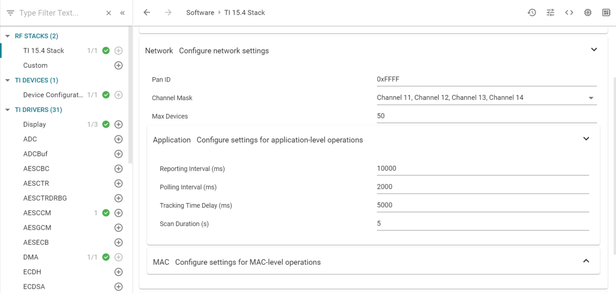
Edit collector.syscfg
- Open the file:
collector_YOURBOARD_LAUNCHXL_tirtos_ccs/collector.syscfgto be modified to change the poll interval.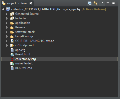
- In RF STACKS, open up the TI 15.4 Stack module. Expand the Network section.
Then expand the Application section and set the Reporting Interval to 10000.
This will set the reporting interval to 10 seconds so we can see the
changes separately.
- In RF STACKS, open up the TI 15.4 Stack module. Expand the Network section.
Then expand the Application section and set the Reporting Interval to 10000.
This will set the reporting interval to 10 seconds so we can see the
changes separately.
Edit collector.h
Open the file:
collector_YOURBOARD_LAUNCHXL_tirtos_ccs/application/collector/collector.hto be modified to add in new definitions and update the frame control.Add the generic sensor to the frame control config parameters. The frame control is used for processing sensor data and correctly parsing the data to know where the data is in the message:
/* Default configuration frame control */
#define CONFIG_FRAME_CONTROL (Smsgs_dataFields_tempSensor | \
                            Smsgs_dataFields_lightSensor | \
                            Smsgs_dataFields_humiditySensor | \
                            Smsgs_dataFields_msgStats | \
                            Smsgs_dataFields_configSettings | \
                            Smsgs_dataFields_genericSensor)
Add in the last dataField to the define
Add new function
Collector_sendGenericRequestdefinition. This function will be used to build and send generic messages on the collector./*! * @brief Build and send the generic message to a device. * * @param pDstAddr - destination address of the device to send the message * * @return Collector_status_success, Collector_status_invalid_state * or Collector_status_deviceNotFound */ extern Collector_status_t Collector_sendGenericRequest(ApiMac_sAddr_t *pDstAddr);
Edit collector.c
Open the file:
collector_YOURBOARD_LAUNCHXL_tirtos_ccs/application/collector/collector.cto be modified to include the ability to read the generic sensor data from the incoming data buffer.Update the
processSensorDatafunction. ThisprocessSensorDatafunction is called by thedataIndCBfunction when a data cmdID is sent by the sensor and is used to receive the data from the sensor, and then parse through the data using the dataFields we made in thesmsgs.hfile.static void processSensorData(ApiMac_mcpsDataInd_t *pDataInd) { ... ... if(sensorData.frameControl & Smsgs_dataFields_humiditySensor) { sensorData.humiditySensor.temp = Util_buildUint16(pBuf[0], pBuf[1]); pBuf += 2; sensorData.humiditySensor.humidity = Util_buildUint16(pBuf[0], pBuf[1]); pBuf += 2; } if(sensorData.frameControl & Smsgs_dataFields_genericSensor) { sensorData.genericSensor.genericRawData = Util_buildUint16(pBuf[0], pBuf[1]); pBuf += 2; } ... }Add in the new function
Collector_sendGenericRequest. This function is used to request generic sensor data from the sensor:/*! Build and send the generic message to a device Public function defined in collector.h */ Collector_status_t Collector_sendGenericRequest(ApiMac_sAddr_t *pDstAddr) { Collector_status_t status = Collector_status_invalid_state; /* Are we in the right state? */ if(cllcState >= Cllc_states_started) { Llc_deviceListItem_t item; /* Is the device a known device? */ if(Csf_getDevice(pDstAddr, &item)) { uint8_t buffer[SMSGS_GENERIC_REQUEST_MSG_LEN]; /* Build the message */ buffer[0] = (uint8_t)Smsgs_cmdIds_genericReq; sendMsg(Smsgs_cmdIds_genericReq, item.devInfo.shortAddress, item.capInfo.rxOnWhenIdle, SMSGS_GENERIC_REQUEST_MSG_LEN, buffer); status = Collector_status_success; } else { status = Collector_status_deviceNotFound; } } return(status); }
Edit csf.c
Open the file:
collector_YOURBOARD_LAUNCHXL_tirtos_ccs/application/collector/csf.cto be modified.Add in the status line for CUI to show the generic Sensor data on UART. This line will be used as a variable pointer to the status line we want to reference when printing to the line.
/******************************************************************************
Global variables
*****************************************************************************/
...
uint32_t collectorStatusLine;
uint32_t deviceStatusLine;
uint32_t numJoinDevStatusLine;
uint32_t genericStatusLine;
In
Csf_init, change the number of status lines to 4. To add in our additional line, we will need the max number of lines to increase.void Csf_init(void *sem) { ... #ifdef LPSTK clientParams.maxStatusLines = 5; #else clientParams.maxStatusLines = 4; #endif ... }Also in
Csf_init, initialize the generic Sensor status line:void Csf_init(void *sem) { ... #ifdef LPSTK CUI_statusLineResourceRequest(csfCuiHndl, "LPSTK Data", true, &lpstkDataStatusLine); #endif /* LPSTK */ CUI_statusLineResourceRequest(csfCuiHndl, "Number of Joined Devices", false, &numJoinDevStatusLine); CUI_statusLineResourceRequest(csfCuiHndl, "Generic Cnt", true, &genericStatusLine); #if !defined(AUTO_START) CUI_statusLinePrintf(csfCuiHndl, collectorStatusLine, "Waiting..."); #endif /* AUTO_START */ ... }In
Csf_deviceSensorDataUpdate, add a line to update the generic Sensor status line:void Csf_deviceSensorDataUpdate(ApiMac_sAddr_t *pSrcAddr, int8_t rssi, Smsgs_sensorMsg_t *pMsg) { ... if(pMsg->frameControl & Smsgs_dataFields_bleSensor) { CUI_statusLinePrintf(csfCuiHndl, deviceStatusLine, "ADDR:%2x%2x%2x%2x%2x%2x, UUID:0x%04x, " "ManFac:0x%04x, Length:%d, Data:0x%02x", pMsg->bleSensor.bleAddr[5], pMsg->bleSensor.bleAddr[4], pMsg->bleSensor.bleAddr[3], pMsg->bleSensor.bleAddr[2], pMsg->bleSensor.bleAddr[1], pMsg->bleSensor.bleAddr[0], pMsg->bleSensor.uuid, pMsg->bleSensor.manFacID, pMsg->bleSensor.dataLength, pMsg->bleSensor.data[0]); } else { CUI_statusLinePrintf(csfCuiHndl, deviceStatusLine, "Sensor - Addr=0x%04x, Temp=%d, RSSI=%d", pSrcAddr->addr.shortAddr, pMsg->tempSensor.ambienceTemp, rssi); CUI_statusLinePrintf(csfCuiHndl, genericStatusLine, "%d", pMsg->genericSensor); #ifdef LPSTK ... }
Flashing your collector
Connect the "Collector" LaunchPad to the PC
Build the project and download it to the LaunchPad by selecting the collector project in the project explorer and clicking the green bug (or hitting F11). This loads the collector
.outfile onto the launchpad.When programming is finished, terminate the debug session by clicking the red square (or, select Run→Terminate).
Troubleshooting: CCS says source file could not be found
Sometimes, after closing and then reopening CCS, it may display an error message saying a source file could not be found, and request you to hit F5 to refresh. Simply pressing F5 does not work. To clear this error message and solve the issue, you need to right click on the containing folder in the project explorer (e.g. the folder "Application"), and select Refresh.
Task 2: Building and loading the sensor example with new generic functionality
Sensor Overview
In this task, you will:
- Learn about some of the sensor control loops
- Learn about how the sensor uses frame controls to control what is sent by the sensor
- Learn how to build sensor messages to be sent to the collector
- Learn how the sensor handles buttons and how to use the button presses as a trigger
Sensor Implementation
Repeat Task 1, but this time select the sensor project when importing.
Update the Channel Mask!
Make sure you did not forget to change the channel mask for the sensor project as well.
Copy all changes to the collector's version of "smsgs.h" to the sensor's version of the file.
Edit sensor.c
Open up the file
sensor_YOURBOARD_LAUNCHXL_tirtos_ccs/application/sensor/sensor.cand add in the following functionality:Add in the new global variable. This will serve as a pointer to help fill in the sensor data message being sent to the collector:
/******************************************************************************
Global variables
*****************************************************************************/
extern uint16_t generic_sensor_val;

static Smsgs_genericSensorField_t genericSensor =
{
0
};
Update
Sensor_initfunction to include the generic Sensor config settings.Sensor_initis used to intialize the sensor on start up. We need to set the frame control configuration to attach generic sensor data in its data messages:#endif /* LPSTK */ configSettings.frameControl |= Smsgs_dataFields_msgStats; configSettings.frameControl |= Smsgs_dataFields_configSettings; #ifdef DMM_CENTRAL configSettings.frameControl |= Smsgs_dataFields_bleSensor; #endif configSettings.frameControl |= Smsgs_dataFields_genericSensor;In
Sensor_process, add in the call for updating the generic display.Sensor_processis the loop that processes sensor tasks throughout the device's life cycle. This will call a function to update our CUI status line for generic data:#ifdef DISPLAY_PER_STATS /* Is it time to update the PER display? */ if(Sensor_events & SENSOR_UPDATE_STATS_EVT) { Ssf_displayPerStats(&Sensor_msgStats); /* Clear the event */ Util_clearEvent(&Sensor_events, SENSOR_UPDATE_STATS_EVT); } #endif /* DISPLAY_PER_STATS */ /* Update the generic sensor count on CUI */ Ssf_displayGenericCnt();In
dataIndCB, update to include a case statement for a generic Sensor request.dataIndCBis a callback function that gets triggered when the sensor receives a packet, and if the cmdId indicates a request for sensor data, the sensor will respond. We need to add a case for generic messages so that when the sensor tries to send a message of generic type, we can pass in the correct parameters to build the message properly.case Smsgs_cmdIds_DeviceTypeReq: /* Make sure the message is the correct size */ if(pDataInd->msdu.len == SMSGS_DEVICE_TYPE_REQUEST_MSG_LEN) { /* Only send data if sensor is in the network */ if ((Jdllc_getProvState() == Jdllc_states_joined) || (Jdllc_getProvState() == Jdllc_states_rejoined)) { Sensor_sendDeviceTypeResponse(); } } break; case Smsgs_cmdIds_genericReq: if(pDataInd->msdu.len == SMSGS_GENERIC_REQUEST_MSG_LEN) { /* send the response message directly */ cmdBytes[0] = (uint8_t) Smsgs_cmdIds_genericRsp; cmdBytes[1] = Ssf_genericCMD(); Sensor_sendMsg(Smsgs_cmdIds_genericRsp, &pDataInd->srcAddr, true, SMSGS_GENERIC_RESPONSE_MSG_LEN, cmdBytes); } break;Update
processSensorMsgEvtfunction to let the sensor copy the generic sensor data into the value. This function is the event handler for when the sensor is tasked with building and sending sensor data. We need to add in the generic sensor data so that the data is sent to the collector:... if(sensor.frameControl & Smsgs_dataFields_configSettings) { sensor.configSettings.pollingInterval = configSettings.pollingInterval; sensor.configSettings.reportingInterval = configSettings .reportingInterval; } if(sensor.frameControl & Smsgs_dataFields_genericSensor) { memcpy(&sensor.genericSensor, &genericSensor, sizeof(Smsgs_genericSensorField_t)); }Update
readSensorsfunction to set the generic Sensor raw data to the correct value. This function is called when the sensor wants to read its sensors. We will use this as an opportunity to update the generic raw data variable with our internal generic sensor value:... accelerometerSensor.xTiltDet = accel.xTiltDet; accelerometerSensor.yTiltDet = accel.yTiltDet; #endif /* LPSTK */ genericSensor.genericRawData = generic_sensor_val; }Update the function
sendSensorMessageto allow for adding the length of the generic sensor value to the length of the message. This function is used to build the sensor data messages. In the code below, we are adding the size of our generic data to the message length so that we reserve space in the message for our data:... if(pMsg->frameControl & Smsgs_dataFields_configSettings) { len += SMSGS_SENSOR_CONFIG_SETTINGS_LEN; } if(pMsg->frameControl & Smsgs_dataFields_genericSensor) { len += SMSGS_SENSOR_GENERIC_LEN; }Also in
sendSensorMessage, add the generic raw data into the buffer:... if(pMsg->frameControl & Smsgs_dataFields_humiditySensor) { pBuf = Util_bufferUint16(pBuf, pMsg->humiditySensor.temp); pBuf = Util_bufferUint16(pBuf, pMsg->humiditySensor.humidity); } if(pMsg->frameControl & Smsgs_dataFields_genericSensor) { pBuf = Util_bufferUint16(pBuf, pMsg->genericSensor.genericRawData); }Update
validateFrameControlfunction to add in a new frame control. This function is used to filter the frame control to verify that the correct data is being added into the frames we are building:... if(frameControl & Smsgs_dataFields_configSettings) { newFrameControl |= Smsgs_dataFields_configSettings; } if(frameControl & Smsgs_dataFields_genericSensor) { newFrameControl |= Smsgs_dataFields_genericSensor; }
Edit ssf.h
Open the file
sensor_YOURBOARD_LAUNCHXL_tirtos_ccs/application/sensor/ssf.hto add in a new definition for a function that will be used to update our UART display:Add in the function definitions:
#endif /* DISPLAY_PER_STATS */

/*!
* @brief       The application calls this function to print updated Generic Count to the display.
*/
extern void Ssf_displayGenericCnt(void);
Edit ssf.c
Open the file
sensor_YOURBOARD_LAUNCHXL_tirtos_ccs/application/sensor/ssf.cto add in new code:Add in the following public variable. This will be where we store how many times we click the button to increment our generic data value:
/******************************************************************************
Public variables
*****************************************************************************/
uint16_t generic_sensor_val = 0;
Add in a new status line variable for the generic Sensor status line for our CUI:
uint32_t sensorStatusLine;
uint32_t perStatusLine;
/* Define status line for generic sensor */
uint32_t genericStatusLine;
In
Ssf_init, add in the following code. Below we are incrementing the number of status lines to allow for our generic data to show on the display. We are also registering the generic line we declared earlier:void Ssf_init(void *sem) { ... clientParams.maxStatusLines = 1; #ifdef DISPLAY_PER_STATS clientParams.maxStatusLines++; #endif /* DISPLAY_PER_STATS */ #ifdef FEATURE_SECURE_COMMISSIONING clientParams.maxStatusLines++; #endif /* FEATURE_SECURE_COMMISSIONING */ #ifdef SECURE_MANAGER_DEBUG clientParams.maxStatusLines++; #endif /* SECURE_MANAGER_DEBUG */ #ifdef SECURE_MANAGER_DEBUG2 clientParams.maxStatusLines++; #endif /* SECURE_MANAGER_DEBUG2 */ #ifdef FEATURE_NATIVE_OAD clientParams.maxStatusLines++; #endif /* FEATURE_NATIVE_OAD */ /* Add extra status line for the generic output */ clientParams.maxStatusLines++; ... ... #ifdef DISPLAY_PER_STATS CUI_statusLineResourceRequest(ssfCuiHndl, "Sensor PER", false, &perStatusLine); #endif /* Register a status line for generic sensor reading */ CUI_statusLineResourceRequest(ssfCuiHndl, "Generic Cnt", false, &genericStatusLine); ... ... }In
Ssf_processEvents, add in a line to increment the counter for the generic sensor value to be incremented whenever the left button is pressed. This function is a event loop used to run some of the application's events. This will handle any button presses. So this is where we need to add in code for toggling our generic data value when the left button is pressed:else if(keys == gLeftButtonHandle) { if(started == false) { CUI_statusLinePrintf(ssfCuiHndl, sensorStatusLine, "Starting"); /* Tell the sensor to start */ Util_setEvent(&Sensor_events, SENSOR_START_EVT); /* Wake up the application thread when it waits for clock event */ Semaphore_post(sensorSem); } else { /* Send LED toggle request to identify collector */ Sensor_sendIdentifyLedRequest(); generic_sensor_val ++;Add in the new function to update the UART display:
#endif /* DISPLAY_PER_STATS */

void Ssf_displayGenericCnt(void)
{
  CUI_statusLinePrintf(ssfCuiHndl, genericStatusLine, "%d", generic_sensor_val);
}
Flashing your sensor
Connect the "Sensor" LaunchPad to the PC
Build the project and download it to the LaunchPad by selecting the sensor project in the project explorer and clicking the green bug (or hitting F11)
When programming is finished, terminate the debug session by clicking the red square (or, select Run→Terminate).
Troubleshooting: CCS says source file could not be found
Sometimes, after closing and then reopening CCS, it may display an error message saying a source file could not be found, and request you to hit F5 to refresh. Simply pressing F5 does not work. To clear this error message and solve the issue, you need to right click on the containing folder in the project explorer (e.g. the folder "Application"), and select Refresh.
Task 3: Using the Collector and Sensor
Close CCS
Make sure no terminal program is running.
Disconnect, then reconnect both CC13x2 LaunchPads to your PC. Otherwise, the LaunchPads' Application UART may not be available.
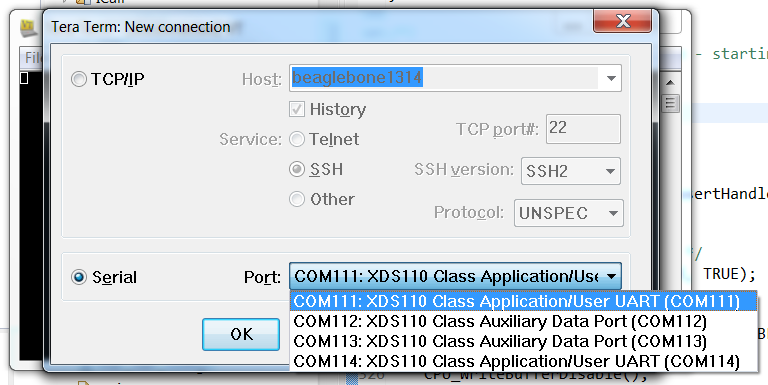
Open two instances of the terminal program, connect each to a different LaunchPad's COM port - these ports should have the word 'UART' in their names. For example, in the following image, the you should select COM111 and COM114:
Configure the UARTs as follows:
- Baud rate: 115200
- Data: 8 bit
- Parity: none
- Stop: 1 bit
- Flow control: none.
Reset each of the LaunchPads to Factory New state by pressing and holding BTN-2, and then pressing the Reset button (while BTN-2 is held down).
Observe and Understand
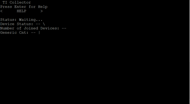
- The collector terminal should look like this:
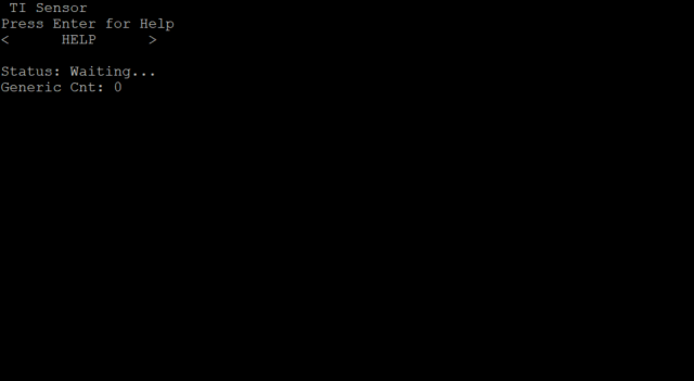
- The sensor terminal like this:
- The collector terminal should look like this:
On the Collector UART, use the right arrow to move over into the
NETWORK ACTIONSmenu and press enter.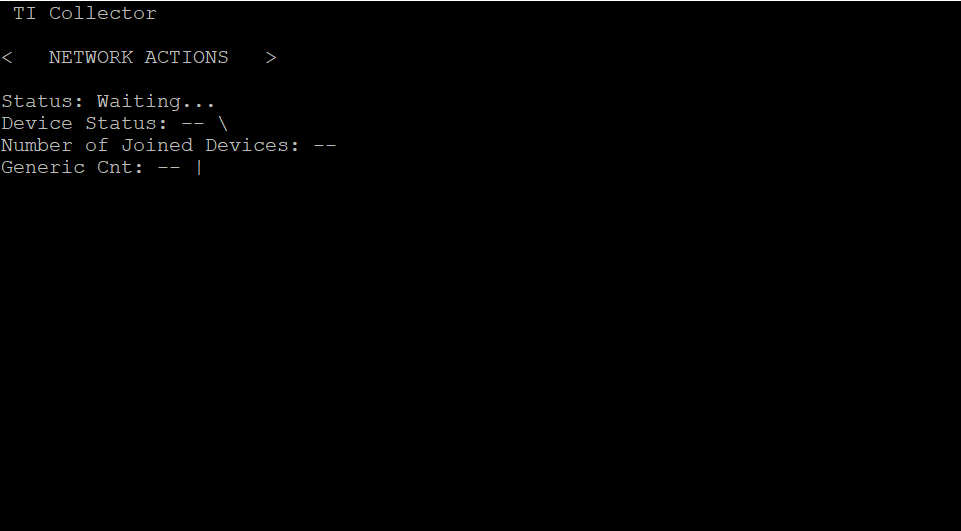
Press enter on the
FORM NWKOption, and wait for the Collector to initialize.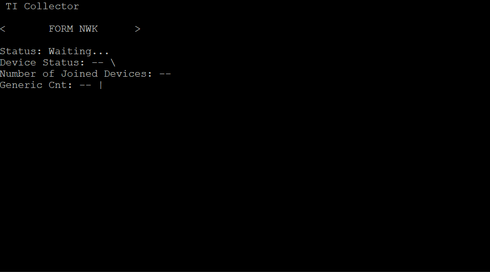
Use the right arrow once to move to the
OPEN NWKoption and hit enter.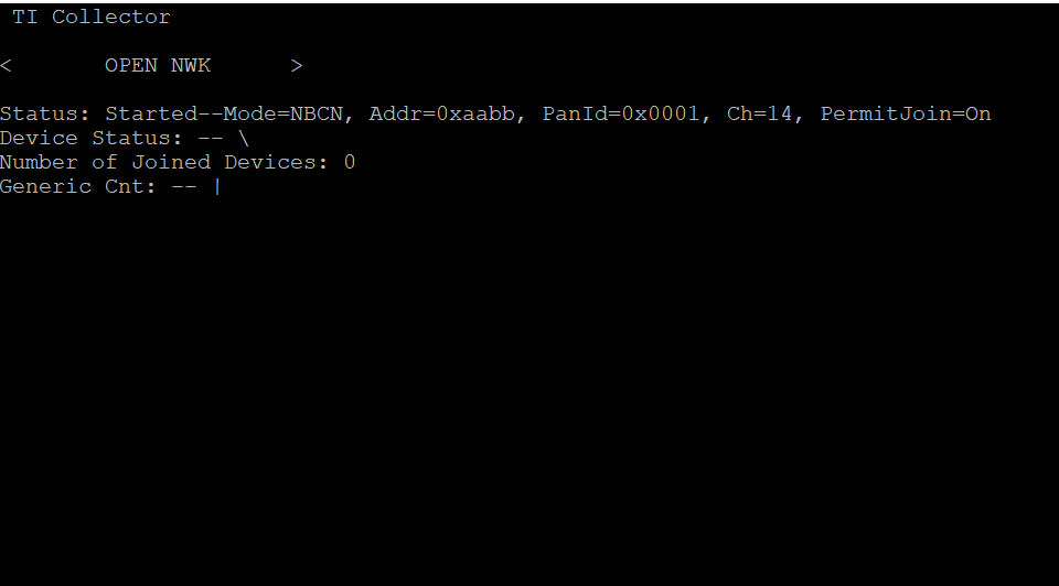
Now on the Sensor UART, use the right arrow to move over into the
NETWORK ACTIONSmenu and press enter.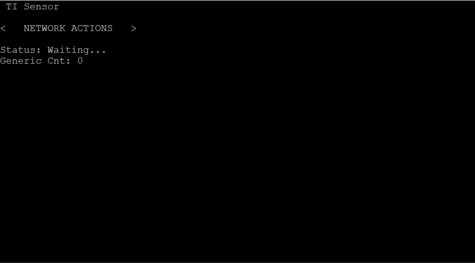
Then press enter on the
ASSOCIATEoption.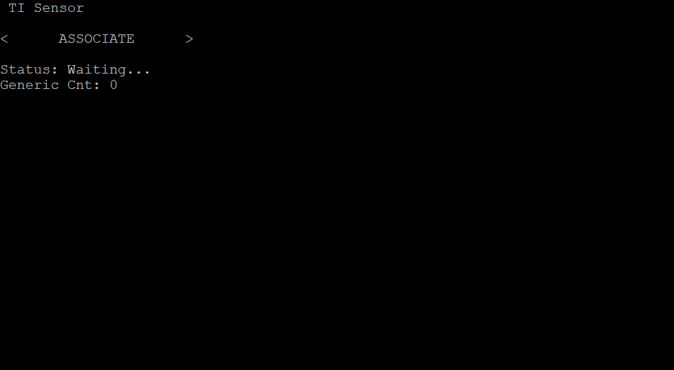
Once the sensor is connected, you can freely press the left button on the Sensor launchpad and watch as the generic count increases. After a few seconds, the collector's value should also increment.
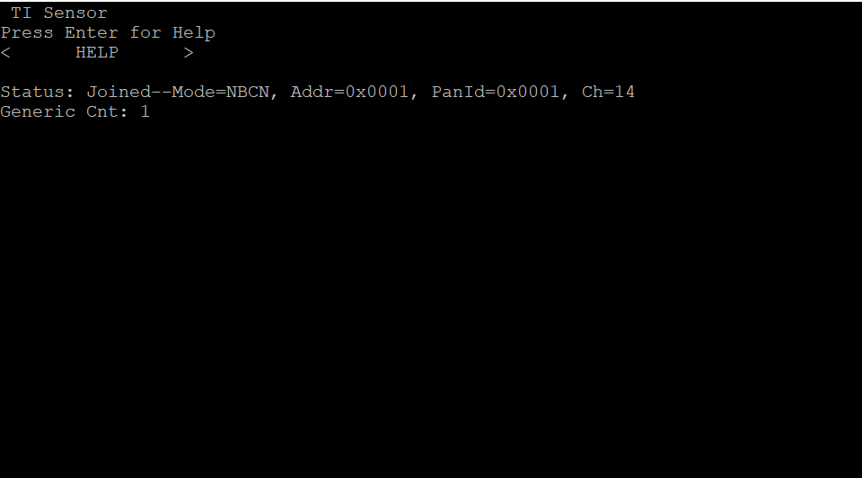
Observe and Understand
The sensor will join the network after a short while, indicated by the red LED turning on on the sensor (otherwise, see Troubleshooting below). The collector's terminal will say "Joined: 0xX" where 0xX is the sensor ID, and the sensor's terminal will say "Status: Joined--Mode=NBCN, Addr=0xX, PanId=0x0001, Ch=x" (0xX is the sensor ID), indicating successful network connection.
Troubleshooting
If the sensor does not join after a short while, please reset it using the reset button.
References
TI 15.4-Stack are at http://www.ti.com/wireless-connectivity/simplelink-solutions/sub-1-ghz/overview.html
CC13xx/CC26xx Software Overview – Available at http://www.ti.com/tool/cc13xx-sw and http://www.ti.com/tool/SIMPLELINK-CC13X2-26X2-SDK.
CC13x0 Technical Reference Manual – Available here
CC13x2/CC26x2 Technical Reference Manual – Available here
This work is licensed under a Creative Commons Attribution-NonCommercial-NoDerivatives 4.0 International License.