Introduction
The SimpleLink™ Software Development Kits (SDKs) includes TI-RTOS support.
TI-RTOS accelerates development schedules by eliminating the need to create basic system software functions from scratch. TI-RTOS scales from a minimal footprint real-time multitasking kernel - TI-RTOS Kernel (formerly known as SYS/BIOS) - to a complete RTOS solution including protocol stacks, multi-core communications, device drivers and power management. By providing essential system software components that are pre-tested and pre-integrated, TI-RTOS enables developers to focus on differentiating their application.
TI-RTOS is included in all SimpleLink SDKs.
Here's what we'll learn:
- TI-RTOS support in SimpleLink SDK
- Main components of TI-RTOS
This module includes quite a bit of text before the lab. Some people find this helpful and others feel that it slows down the whole session. If you are in the latter camp, please feel free to jump directly to the lab. For more details about specific features, you can go back and read the following content as needed.
Recommended Background Reading
It is strongly recommend you are familiar with the following item.
A Brief History of TI-RTOS
First let's look at the history of the RTOSes that have been developed and supported by Texas Instruments
- DSP/BIOS: 1999-current. RTOS that is available for C2xxx, MSP430, C54xx, C55xx, and C6xxx devices. Currently in maintenance-mode only. Available as a stand-alone product.
- TI-RTOS: 2008-current. Started as SYS/BIOS and was re-branded to TI-RTOS in 2014. TI-RTOS is available for C2xxx, MSP43x, C6xxx, CortexA and CortexM devices. Active development of new features is ongoing. Currently running on millions of devices (e.g. IoT, automotive, industrial, etc.).
TI-RTOS Product
For several years, TI-RTOS has been available three ways
- Processors SDK: For Keystone and Sitara devices, the TI-RTOS kernel is included in the Processors SDK.
- SYS/BIOS product: The kernel product is available as a stand-alone product. This product is recommended for non-Concerto C2000 devices or for customers that want a version of TI-RTOS that is newer than the ones supplied in the Processors SDKs.
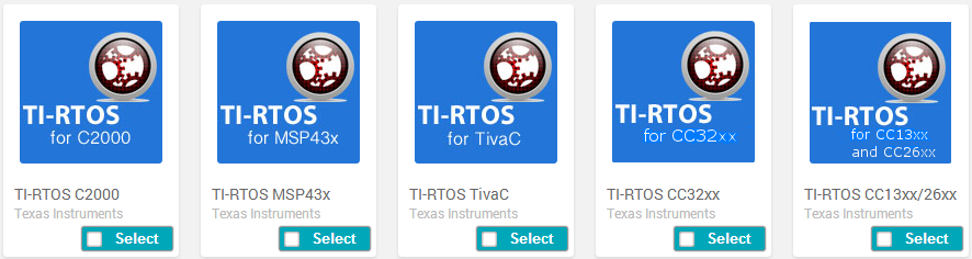
TI-RTOS Product: These products contained both TI-RTOS and RTOS-aware drivers (e.g. UART, I2C, etc.) for MCU devices. The following TI-RTOS products are available:
Going forward, for the MSP432, CC32xx, CC26xx, or CC13xx devices, all of TI-RTOS product content is now in the SimpleLink SDK. The existing TI-RTOS products for these devices will still be available, but for new customer development, we strongly recommend that you use the corresponding SimpleLink SDK.
For customers that are currently using a TI-RTOS product (e.g. TI-RTOS for CC13xx/CC26xx v2.21.00.06) and want a new release, they should get the new corresponding SimpleLink SDK product. A migration guide in the SimpleLink SDK gives instructions on how to make the migration from a TI-RTOS product to a SimpleLink SDK.
TI-RTOS and TI Drivers for MSP432, CC32xx, CC13xx, or CC26xx SimpleLink devices are now in SimpleLink SDK products
Going forward, no new TI-RTOS products will be available for these SimpleLink devices. TI-RTOS and SYS/BIOS delivery for non-SimpleLink devices (first two above bullets) will continue as-is with new releases as warranted.
TI-RTOS Kernel
At the center of TI-RTOS is the kernel. We'll look at the main modules of the kernel in this section. For more specific details on any of these kernel modules,
please refer to the Kernel Documentation section of the
SimpleLink SDK Documentation Overview: <SimpleLink_SDK_Install_Dir>\docs\Documentation_Overview.html
The TI-RTOS kernel code is in the ROM for CC13xx and CC26xx devices.
This allows the application to utilize more of the flash. Please note: the kernel still requires a small amount of flash and/or RAM memory.
Scheduler
The main function of the kernel is the scheduler. The scheduler is responsible for making sure the highest priority thread is running.
Let's look at the four different types of threads in TI-RTOS.
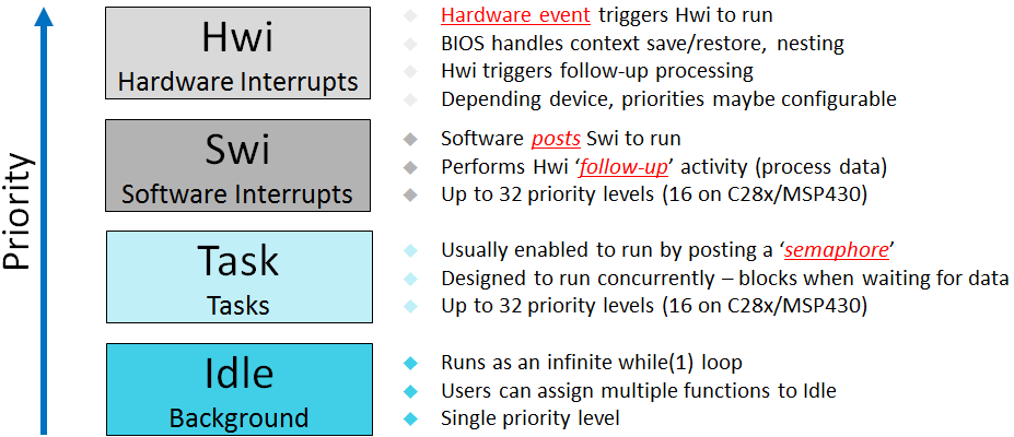
Let's go into a little more detail for each one.
Hardware Interrupts (Hwi): Hwi run to completion. They don't block on anything. They can get preempted by a higher priority Hwi. All Hwi share the same stack (system stack).
Hwi can be written in 'C'. They are managed by the TI-RTOS scheduler with an exception: zero-latency interrupts. Applications can designate that any interrupt be a "zero-latency" interrupt. This means the TI-RTOS scheduler does not interact with that interrupt. We call it a zero-latency interrupt because the TI-RTOS kernel adds zero latency to the execution of these interrupts. The downside to zero-latency interrupts is that they cannot call into the kernel scheduler APIs (e.g.
Semphore_post(), etc.).Software Interrupts (Swi): The Swi thread is similar to a Hwi except it is software initiated instead of hardware. It also runs to completion. It shares the same system stack with the Hwi threads. Since Swi run at a lower priority than Hwi, they are useful for doing deferred Hwi work to minimize interrupt latency.
Tasks: A Task is a common OS thread. Each task has its own stack (where it maintains its state). Since it has its own stack, a task can block. There is no maximum number of allowable tasks (system memory permitting).
Here are the states for a Task.
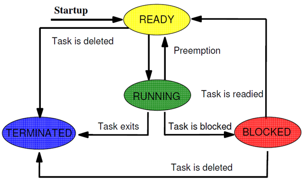
Idle: Idle is a special task. It runs at the lowest priority (0 is the lowest priority, 1 is the next lowest, ..., (Task_numPriorities - 1) is the highest priority). The Idle task performs background tasks like system stack checking (if enabled), CPU Load determination (if enabled), etc. It also executes functions plugged in by the application.
Low power devices can be placed into lower power modes when the Idle thread runs.
For a preemption example, please refer to the RTOS Concepts workshop. There is an execution graph of a typical application.
Thread Communication
TI-RTOS contains several thread communication mechanisms. Here are the main ones that are used.
- Semaphores: An object used to control access to a common resource. They can be used for task synchronization and mutual exclusion.
- Mailboxes: Message passing module
- Queues: Doubly linked list (no synchronization though)
- Gates: Used to protect concurrent access to critical data structures. A Gate is a reentrant mutex.
- Events: Module which allows synchronization via multiple events.
Let's look at a couple of these in action.
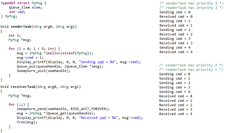
Semaphore Example 1: Here is an example of a semaphore being used to manage a linked list (Queue). This semaphore is a counting semaphore since it is potentially managing multiple elements on the linked list. After an element is placed on the queue, the semaphore is posted to wake up the receiver. We want a counting semaphore here (with initial value of 0) since we may put multiple elements on the linked list before the receiver gets them.
The right side of the picture shows the IDE console output depending on the priority setting of the respective tasks. Remember that TI-RTOS is a preemptive scheduler, so once the highest priority thread is ready, it will run.
Note:
Queue_put()andQueue_get()add/remove elements from the linked list in an atomic manner. Thread-safety is guaranteed. Also note that the user's data structure provides theprevandnextpointers via theQueue_Elemfield in theirMyMsgstructure. This avoids memory allocation in the Queue module and also allows the linked list to be infinitely long (memory permitting).Semaphore Example 2: In this example, the semaphore is being treated as a mutex (MUTual EXclusion). If another task wanted to access the global structure
myGlobal, it should use the same semaphore to wrap the changes. This protects the updating of the shared structure. The area being protected is often called a critical region.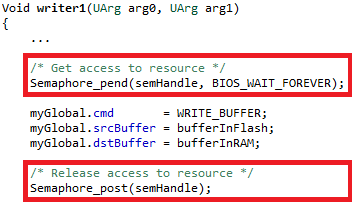
Let's look at what happens if we did not do this. Say
writer1(priority 1) andwriter2(priority 2) tasks both modify this structure andreaderreads and acts on this struct. Let's saywriter1is running andwriter2is blocked. Here is a situation where without the semaphore protection, corruption can occur.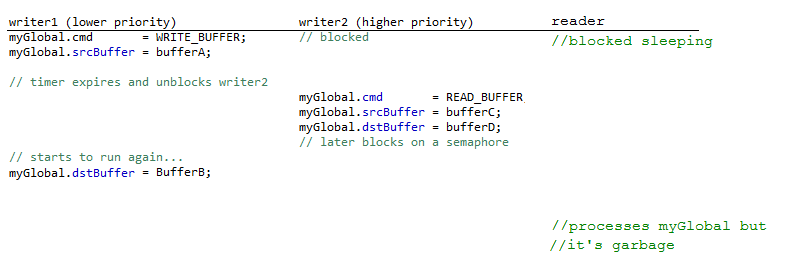
Now the request is to have bufferC read into bufferB...no one asked for that! If the semaphore was used, writer1 would have completed updating the entire global first. Please note this is a somewhat contrived example, but hopefully clearly shows why managing critical regions is important.
When this semaphore was created, it could have been binary (since the count will only be 0 or 1) and the initial count should have been 1 (to allow the first
Semaphore_pend()to succeed).Other types of mutual exclusion...
The Gate module can also be used for mutual exclusion. For such short critical regions, you can also disable/restore interrupts (
Hwi_disable()&Hwi_restore()).Mailbox Example: Here is a modified version of the examples/rtos/Board/sysbios/mailbox example (error checking/output removed). The
writerTaskis sending messages to thereaderTask. The contents of the message are application-specific.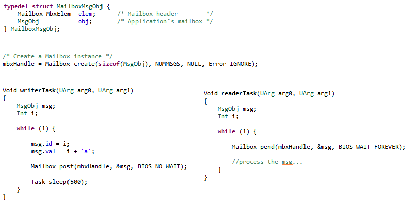
Please note: specify different timeouts on both the sending and receiving ends. This allows a Mailbox to be used by a Hwi, Swi or Task.
Timing Services
- Timer: Module that allows management of hardware timers.
- Clock: TI-RTOS, by default, uses a timer to drive timing services (e.g.
Task_sleep(), etc.). Applications can plug functions into the Clock module that will be called at the rate they request. Your plugged-in Clock functions can be periodic or one-shot. - Seconds: Unified front-end to the device's RTC timer.
Memory Managers
TI-RTOS offers many types of memory managers. Here is an overview of the main heap implementations:
| Heap | Description | Reason to use |
|---|---|---|
| HeapMem | Variable size allocation | Very flexible |
| HeapBuf | Fixed size allocation | Fast and deterministic |
| HeapMultiBuf | Multiple fixed size allocation | Fast and deterministic |
| HeapMin | Variable size, growth only | Fast and deterministic (but cannot call free) |
| HeapTrack | Stacking diagnostic heap | Helps find memory leaks, corruption, etc. |
The heaps sit underneath the Memory_alloc() and Memory_free() APIs.
By default, TI-RTOS creates a system (or default) heap. This heap is used when you pass in NULL for the IHeapHandle in Memory_alloc() and Memory_free(). The system heap is also used in malloc() and free() functions (the kernel replaces the RTS malloc() and free() functions). By default, the system heap is a HeapMem instance and the size is controlled by the settings in the linker command files. For example, here is the sizing of the system heap in the MSP_EXP432P401R_TIRTOS.cmd linker file.
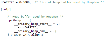
An application can have more than one heap in the application. A common usage is to have the system heap be HeapMem and then create a HeapBuf instance to manage fixed-blocks that can be allocated and freed quickly with no fragmentation (or to be more precise, no external fragmentation). We generally see that the system heap is left as a HeapMem instance because it may be hard to know where all the allocations (and the size of the allocations) in an application are occurring.
POSIX (Portable Operating System Interface) Support
POSIX is an IEEE industry API standard for OS compatibility. The SimpleLink SDK provides support for POSIX APIs on top of TI-RTOS (as it does for FreeRTOS). For details about POSIX, please refer to IEEE POSIX. For a more detailed description of the POSIX support in SimpleLink SDKs, please refer to the POSIX Overview Workshop.
SimpleLink SDK Components and TI-RTOS
TI Drivers
The TI Drivers (including Power Management) are written to be used with the Driver Porting Layer (DPL). The SimpleLink SDK includes a DPL implementation for both FreeRTOS and TI-RTOS.
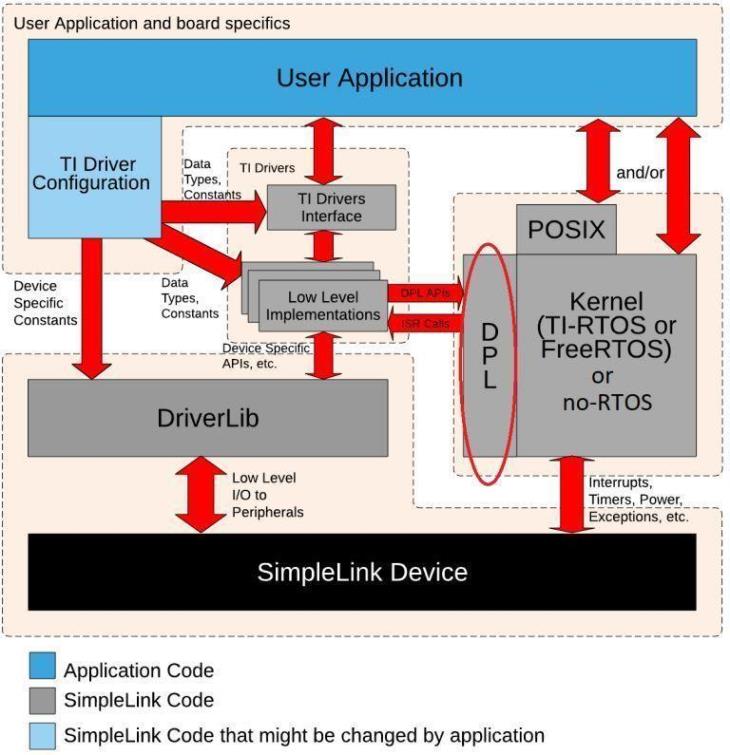
DPL is not a full-feature Operating System Abstraction Layer (OSAL).
It was developed specifically to meet the needs of the TI Drivers. Therefore, it is not recommended that application code use the DPL interface. For application code that wants OS abstraction, please use POSIX APIs, not DPL.
Other SimpleLink SDK Components
TI-RTOS is supported by other SDK components (e.g. third_party\fatfs, ti\display) unless otherwise noted.
TI-RTOS Configuration and Examples
The kernel is built based on the settings in the TI-RTOS kernel configuration file (also called the .cfg file). This file is basically a JavaScript file that can be edited as a text file or graphically (graphically is only available in CCS). As part of the application build, the .cfg file generates the kernel objects and libraries.
There are two different ways for an application to include the TI-RTOS kernel configuration file in the SimpleLink SDKs:
- Application projects include the .cfg file
- Application projects (e.g. TI Drivers examples) point to a TI-RTOS kernel configuration project
The end result of the two approaches are essentially the same. The separate kernel configuration project approach works better when you want to have the same application use TI-RTOS or FreeRTOS.
Kernel Projects
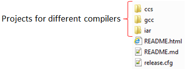
The TI-RTOS kernel is built via a provided project. The examples that are TI-RTOS based (e.g. TI Drivers examples) point to the kernel project. The SDK provides the kernel project in the kernel/tirtos/builds/BOARD/release and debug directories. For example, here is the directory that contains the release.cfg kernel configuration file.
The kernel project is automatically imported when a TI-RTOS example is imported. A copy of the kernel project is made in the workspace.
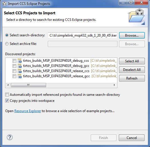
Alternatively, this project can be imported into CCS by selecting Project → Import CCS Projects... and navigating to the kernel/tirtos/builds directory. Then select the desired board and compiler project.
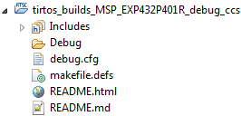
Here is what the imported kernel project looks like. You see the debug.cfg file. Note: the release configuration is used by default for all of the examples.
For more details on how to change or create new TI-RTOS kernel projects, please refer to the "SimpleLink SDK User Guide". We do recommend that you use the debug kernel configuration project while developing your application. It has many nice debug features enabled (e.g. stack overflow checking, assert checking, etc.).
Examples
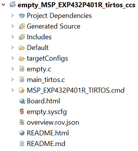
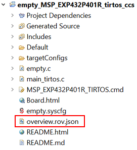
Many examples (e.g. TI Drivers examples) are available for both FreeRTOS and TI-RTOS. When an example is imported, the kernel project is also automatically imported. Here is a picture of the projects when empty was imported.
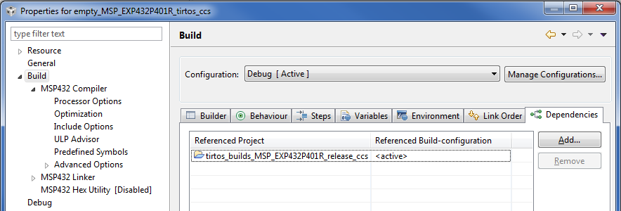
The empty project points to the kernel project via the Project Properties → Build → Dependencies setting. Please refer to the "SimpleLink SDK User Guide" for more details on the management of this setting.
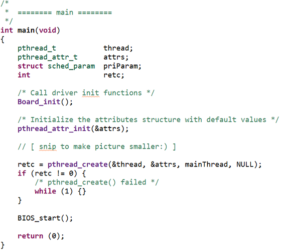
Many of the examples use the POSIX layer to allow them to be used with TI-RTOS or FreeRTOS. All the TI-RTOS specific code is in the main_tirtos.c file (there is a main_freertos.c for FreeRTOS-based examples). The majority of the file uses the POSIX API, but at the end of main(), the call to start the TI-RTOS scheduler is made.
The linker command file is also slightly different from the FreeRTOS one in how it sets up the dynamic heap.
POSIX is not required for TI-RTOS
Even though the TI-RTOS examples use POSIX in the SimpleLink SDK, it is not required. You can use the native TI-RTOS APIs instead or alongside the POSIX APIs if you prefer. Using POSIX is recommended if you
- want an application that is portable across different RTOSes
- you have existing code that uses it
- are comfortable with the slight overhead it introduces
Please refer to the demos\portable and demos\portableNative examples to see a comparison of using POSIX vs the native RTOS APIs.
Debugging Features and Tools
TI-RTOS supports many powerful debugging features. For a nice overview, please watch this Debugging Common Application Issues with TI-RTOS video.
RTOS Object View (ROV)
ROV is a tool in CCS that lets you see see the state of the kernel. Let's run the portable project and look at a couple key things. ROV can be opened when in the debug perspective of CCS via Tools → RTOS Object View (ROV) or Tools → ROV Classic (ROV is also supported in IAR. Please refer to the "SimpleLink SDK Quick Start Guide" for more details).
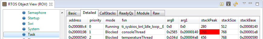
Here is view of the tasks in the system. You can see the three tasks in the system, their priorities and stack usage. Red text (e.g. stackPeak for consoleThread) means the value has changed since the last time you halted the target.
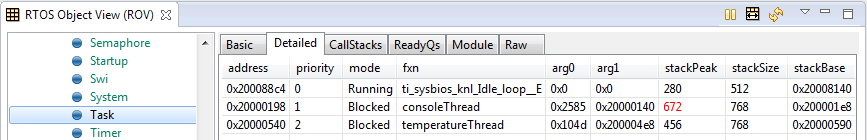
If you made the stack size too small, it can quickly be found in ROV via the red background.
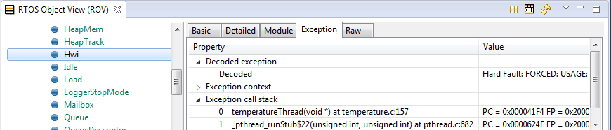
You can also get nice exception handling information from ROV.
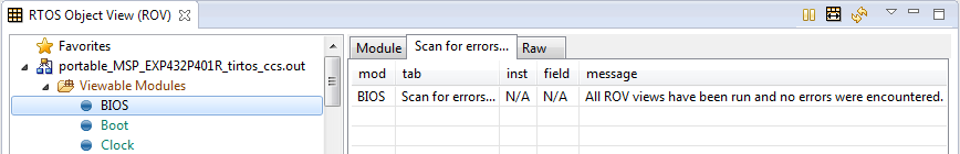
The "BIOS->Scan for errors..." is a fast and easy way to determine if the RTOS is in a bad state (e.g. blown stacks, corrupted data because of bad application pointers or buffer overflows, etc.).
ROV has no overhead on the target. The tool is reading memory down on the target via emulation (note the target must be halted). There is nothing you have to turn on to get ROV support.
Runtime Object View
Starting with CCS 7.1, Runtime Object View (let's call it ROV2 for short) is also available. ROV2 is basically ROV on steroids. You get all the information that was available in ROV but you can see multiple things at once. It includes support for graphs. You can open ROV2 via "Tools->Runtime Object View"
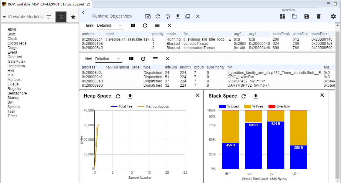
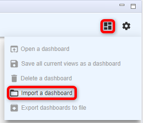
You can save your ROV2 session as a dashboard, so the next time you open ROV2, you can import that dashboard and get your customized view of the target. The TI-RTOS examples (both kernel and TI Drivers) ship a dashboard in the project called overview.rov.json. The overview.rov.json dashboard was used in the above picture.
To load the dashboard, simply select the "Import a dashboard" and import the overview.rov.json.
More information about ROV2 can be found here at
System Analyzer
The System Analyzer tool in CCS allows you to visually see key items like the execution graph, CPU load, average/max/min execution times for code segments, etc. This is accomplished by logging records on the target. The typical use is to have the records maintained in buffers on the target which System Analyzer reads while the target is halted. However there are also runtime reading capabilities for getting the log records off of the target (e.g. UART).
Here is an example of execution of the mutex example in the SDK. The logging of TI-RTOS kernel log records can be turned on (it's on in the debug kernel project). All the context switches are logged on the target and interpreted in CCS.
Okay...this execution graph is a little boring, but you can see how easy it is to see what is happening. You can add in interrupt execution and pending/posting of semaphores to see even more granularity.
Lab: Getting started
Software
- Any SimpleLink SDK
- CCS as specified by your SimpleLink SDK Release Notes (please use Desktop version, not CCS Cloud)
Hardware
- Any supported SimpleLink LaunchPad™ Development Kit
The below steps will use SimpleLink CC13x2/CC26x2 SDK along with the CC26X2R1-LAUNCHXL LaunchPad board. So some of the pictures/directory names/line numbers/sizes/etc. might be slightly different.
Making sure it works
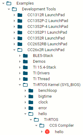
Open your Desktop Code Composer Studio and import the TI-RTOS hello project from your SimpleLink SDK inside of Resource Explorer. We'll be changing the TI-RTOS kernel configuration file and this is not currently supported in CCS Cloud. Make sure to select the "CCS Compiler" version. (Note: some of the following pictures are old, so the exact content might be slightly different).
To test that the software and hardware pre-requisites are fulfilled we are going to build and run the project before going to the first task.
- Our first mission is to build the imported project. Select the project in Project Explorer and build the project.
- When the project is built, we are going to make sure that the hardware and debugger work. To start debugging, press Run → Debug, or press F11.
- When the download is finished, press F8 or the green play button to run.
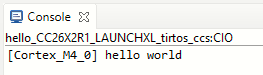
- You should see "hello world". The program terminates after printing the text. For example, this is what it should like like on a CC26X2R1-LAUNCHXL LaunchPad.
On Building
Note that the first time you build the project, the whole TI-RTOS kernel will also be built. This may take a minute or two, but is only done the first time. Subsequent builds will re-use the compiled kernel unless the configuration changes.
Task 1 - Replacing the contents of hello.c
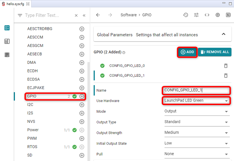
Double-click the hello.syscfg file in your project. This will open the SysCfg editor. Select the "GPIO" module name in the left-hand column and click "ADD" to add another GPIO to your board's configuration. Name the new GPIO CONFIG_GPIO_LED_1 and select the green LED in the Use Hardware field.
Next select the below text and replace the entire contents of hello.c (you can leave the license banner if you want). Then rebuild/reload/run the project. You should get a flashing LED.
/* TI-RTOS Header files */
#include <xdc/std.h>
#include <ti/sysbios/BIOS.h>
#include <ti/sysbios/knl/Task.h>

#include <ti/drivers/GPIO.h>

/* Driver configuration */
#include "ti_drivers_config.h"

void myDelay(int count);

/* Could be anything, like computing primes */
#define FakeBlockingSlowWork()   myDelay(12000000)
#define FakeBlockingFastWork()   myDelay(2000000)

Task_Struct workTask;
/* Make sure we have nice 8-byte alignment on the stack to avoid wasting memory */
#pragma DATA_ALIGN(workTaskStack, 8)
#define STACKSIZE 1024
static uint8_t workTaskStack[STACKSIZE];

void doUrgentWork(void)
{
    GPIO_write(CONFIG_GPIO_LED_1, CONFIG_LED_OFF);
    FakeBlockingFastWork(); /* Pretend to do something useful but time-consuming */
    GPIO_write(CONFIG_GPIO_LED_1, CONFIG_LED_ON);
}

void doWork(void)
{
    GPIO_write(CONFIG_GPIO_LED_0, CONFIG_LED_OFF);
    FakeBlockingSlowWork(); /* Pretend to do something useful but time-consuming */
    GPIO_write(CONFIG_GPIO_LED_0, CONFIG_LED_ON);
}

Void workTaskFunc(UArg arg0, UArg arg1)
{
    while (1) {

        /* Do work */
        doWork();

        /* Wait a while, because doWork should be a periodic thing, not continuous.*/
        myDelay(24000000);
    }
}

/*
 *  ======== main ========
 *
 */
int main(void)
{
    Board_init();
    GPIO_init();

    /* Set up the led task */
    Task_Params workTaskParams;
    Task_Params_init(&workTaskParams);
    workTaskParams.stackSize = STACKSIZE;
    workTaskParams.priority = 2;
    workTaskParams.stack = &workTaskStack;

    Task_construct(&workTask, workTaskFunc, &workTaskParams, NULL);

    /* Start kernel. */
    BIOS_start();

    return (0);
}

/*
 *  ======== myDelay ========
 *  Assembly function to delay. Decrements the count until it is zero
 *  The exact duration depends on the processor speed.
 */
__asm("    .sect \".text:myDelay\"\n"
      "    .clink\n"
      "    .thumbfunc myDelay\n"
      "    .thumb\n"
      "    .global myDelay\n"
      "myDelay:\n"
      "    subs r0, #1\n"
      "    bne.n myDelay\n"
      "    bx lr\n");
hello.c
Orienting ourselves in the code
The Task 1 example comes preconfigured with one TI-RTOS Task already constructed in main(). This task is set up to use the workTaskFunc function as the task function, which in turn uses the GPIO Driver to toggle a LED.
The task is created using the Task_construct in main(). main() also initializes the hardware.
In main(), after BIOS_start() is called, it never returns, but instead gives control to the TI-RTOS scheduler which will call the Task functions of the constructed tasks (e.g. workTaskFunc). Normally, task functions will enter an infinite loop and never return, letting TI-RTOS switch to higher priority tasks, Swi or Hwi.
Task 2 - Debugging Tools
We are going to take a look at some of the built-in features of CCS which can aid in the development of firmware running on TI-RTOS, and also give a better understanding of the multitasking.
Runtime Object View
As discussed above, Runtime Object View (we'll call it ROV2 here for short) can be used to get a snapshot of the whole RTOS. By default the information is only updated via JTAG when the target is halted. First we are going to halt the code as we are toggling the led.
Put a breakpoint on the
FakeBlockingSlowWork()call on thedoWork()function. Do this by double clicking on the area on the left of the line number.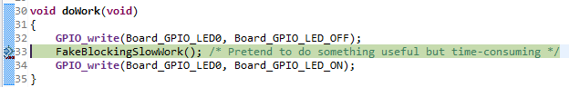
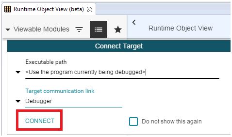
Run so you hit that breakpoint. Next open ROV2 by going to Tools → Runtime Object View. You'll be prompted to connect.
In ROV2, select the "Import a dashboard" icon and select the
overview.rov.jsonfile that is in the project.This dashboard shows which task is currently running on the system, what tasks are blocked, as well as what tasks are ready to run.
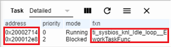
We can see that the workTaskFunc is currently running and we can also see that the stack usage for the task has peaked at 124 of 1024 bytes (STACKSIZE) bytes so far, so no risk of stack overflow. Note: depending on your device, compiler, and versions, the values will probably be different. We generally recommend you start with a larger stack size and then trim it down once everything is working properly.
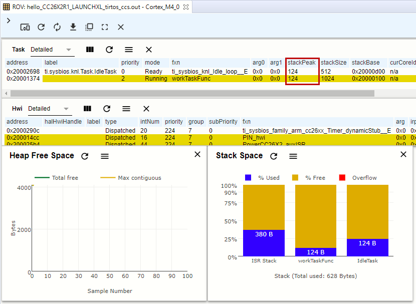
The 124 has a yellow background which means it has changed since the last time it was read.
The memory and stack usage graphs can also be very useful. If you run again to the breakpoint, the values will be updated.
Execution graph
While ROV is handy to get a snapshot view over the current state of the system it is not as easy to get any information about the state of the system over time. For this we use the Execution graph and will need to edit the .cfg file.
Edit the .cfg as text or graphically
You can right-click the .cfg file and edit it as a text file (recommended for this lab) or graphically.
First we need to enable the logging by changing the comments. Open the
hello.cfgand enable the kernel's logging feature. Note: this is turned on in the debug TI-RTOS kernel configuration project used by the driver examples.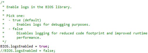
For CC13xx/CC26xx devices, the kernel in the ROM has logs disabled.
To enable the kernel to log events, you cannot use the kernel in the ROM. By removing (or commenting out) the following lines in the .cfg file, the kernel will instead be placed in the CC26xx's flash (and the kernel can log events).
var ROM = xdc.useModule('ti.sysbios.rom.ROM');
if (Program.cpu.deviceName.match(/CC2640R2F/)) {
    ROM.romName = ROM.CC2640R2F;
}
else if (Program.cpu.deviceName.match(/CC26.2/)) {
    ROM.romName = ROM.CC26X2;
}
else if (Program.cpu.deviceName.match(/CC13.2/)) {
    ROM.romName = ROM.CC13X2;
}
else if (Program.cpu.deviceName.match(/CC26/)) {
    ROM.romName = ROM.CC2650;
}
else if (Program.cpu.deviceName.match(/CC13/)) {
    ROM.romName = ROM.CC1350;
}
Add the following lines to the bottom of the
hello.cfgfile. This will configure the kernel to maintain buffers on the target where the log records will reside. Note: this is also in the debug TI-RTOS kernel configuration project used by the driver examples. We're only interested in the kernel's logging so we'll disable the CPU Load logging.var LoggingSetup = xdc.useModule('ti.uia.sysbios.LoggingSetup'); LoggingSetup.sysbiosLoggerSize = 1024; LoggingSetup.loadLogging = false;Rebuild, reload, and run the example for 10-15 seconds (to get a good amount of log data). Remember to remove any breakpoints. Press the Suspend button to pause the execution of the program.
Next, open the Execution Analysis menu by going to Tools → RTOS Analyzer → Execution Analysis. Note: you may be asked to do a one-time setup.
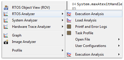
Select only the
Execution GraphAnalysis Feature in the next window, leave everything else as it was and press Start.In the new Execution Graph tab, expand
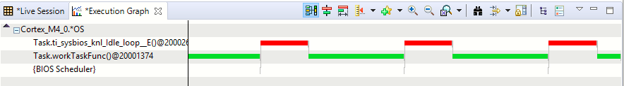
Cortex_M4_0.*OS(or whichever processor is listed for your device) to see thatTask.workTaskFunchas been executing! In fact, it's the only task executing. TheIdletask has not gotten any time at all during the execution of the program.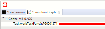
If there is nothing in the execution graph...
We have a small race condition in the tool. If there are no records, please select the Live Session tab and stop/start the collection.
There is only one task running the entire time. It's hogging all of the processor.
How does the logging work?
The TI-RTOS module LoggingSetup, which is part of the Universal Instrumentation Architecture (UIA), sets the UIA module LoggerStopMode up as an interface for the XDC Runtime Log module, which has hooks into the Task, Hwi and Swi modules.
The TI-RTOS configuration script parsing acts as an extra precompile step which can add, remove and configure RTSC (Real-Time Software Component) modules by outputting .c and .h files used for later compilation and linking.
Task 3 - Sleeping well
After looking at the Execution Graph, we can see that we have a problem with one of our tasks hogging all CPU resources. Let's take a look at our workTaskFunc.
void doWork(void)
{
    GPIO_write(CONFIG_GPIO_LED_0, CONFIG_LED_OFF);
    FakeBlockingWork(); /* Pretend to do something useful but time-consuming */
    GPIO_write(CONFIG_GPIO_LED_0, CONFIG_LED_ON);
}

Void workTaskFunc(UArg arg0, UArg arg1)
{
    while (1) {

        /* Do work */
        doWork();

        /* Sleep */
        myDelay(24000000);
    }
}
Work, "sleep", work.
The only thing the task does is execute the doWork function and then goes back to "sleep", except it never does go to sleep. The myDelay function is simply a function which burns CPU cycles in a loop. This is not the correct way to pass time in the RTOS.
One of the easiest ways to pass time in a task is to call Task_sleep(numTicks). Task_sleep will simply make the current task sleep for as many system ticks as is specified in the argument. The current tick rate of the system is needed in order to know how long you will sleep. This is a constant value available via the Clock_tickPeriod variable. The value is the amount of microseconds per clock tick.
Clock_tickPeriod
To use Clock_tickPeriod, remember to include the kernel Clock module header: #include <ti/sysbios/knl/Clock.h>
The value of this variable [µs/tick] is determined when the TI-RTOS .cfg file is parsed. If Clock.tickPeriod = nn; is not present in the .cfg file, the default value is used (1000µs or 1ms). Since the tick period can vary between projects, it's useful to include the variable Clock_tickPeriod in calculations that depend on system clock ticks.
Task 3.1
Add the Clock modules include file after the Task.h include in hello.c.
#include <ti/sysbios/knl/Clock.h>
Task 3.2
- Replace the use of
myDelayto sleep withTask_sleepand use it to sleep for 500ms.- How do you convert an argument in microseconds to an argument in system ticks?
//myDelay(24000000);
Task_sleep(500 * (1000 / Clock_tickPeriod));
- How do you convert an argument in microseconds to an argument in system ticks?
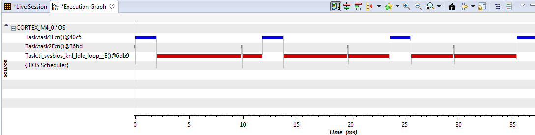
Rebuild/reload/run. Let the code run for a while and have another look at the Execution Graph, does it look any different? Note: you may have to zoom out to see the transitions.
Now we see that Idle was given a chance to run. For low power devices, going into idle will allow the device to transition to lower power modes.
Note: if the task function does not show in the execution graph, you can close reference the task handle in ROVs Task Detailed view.
Number of Log Records
You can control the number of kernel records via the LoggingSetup.sysbiosLoggerSize variable in the .cfg file. Each record is ~20-48 bytes since they are stored as binary codes (not ASCII). In this example we had 1024 bytes, so we get around 30-35 records. For a more complex execution application, you'll probably need more Log records for a detailed execution graph.
Task 4 - Executing urgent work
Next we are going to expand on the original code by adding a doUrgentWork function and task.
In our system, this will represent the most important work processing the system needs to do. This is more important than the work done by the workTask and should execute as quickly as possible.
Setting up the new task
- First copy, paste and rename the
workTaskFuncfunction to create a new task function calledurgentWorkTaskFunc. - Let
urgentWorkTaskFunccalldoUrgentWork. - Copy, paste and rename the
Task_Structand the task stack storage as well forurgentTask. - Construct the new task (copy and rename the parameters and the construction) and set the priority of the new task to 1. We'll play with this later... Note: Higher priority number means higher priority.
- Reduce the
Task_sleep()time to 50ms inurgentWorkTaskFunc.
   /* TI-RTOS Header files */
  #include <xdc/std.h>
  #include <ti/sysbios/BIOS.h>
  #include <ti/sysbios/knl/Task.h>
  #include <ti/sysbios/knl/Clock.h>

  #include <ti/drivers/GPIO.h>

  /* Driver configuration */
  #include "ti_drivers_config.h"

  void myDelay(int count);

  /* Could be anything, like computing primes */
  #define FakeBlockingSlowWork()   myDelay(12000000)
  #define FakeBlockingFastWork()   myDelay(2000000)

  Task_Struct workTask;
  Task_Struct urgentWorkTask;
  /* Make sure we have nice 8-byte alignment on the stack to avoid wasting memory */
  #pragma DATA_ALIGN(workTaskStack, 8)
  #define STACKSIZE 1024
  static uint8_t workTaskStack[STACKSIZE];
  static uint8_t urgentWorkTaskStack[STACKSIZE];

  void doUrgentWork(void)
  {
      GPIO_write(CONFIG_GPIO_LED_1, CONFIG_LED_OFF);
      FakeBlockingFastWork(); /* Pretend to do something useful but time-consuming */
      GPIO_write(CONFIG_GPIO_LED_1, CONFIG_LED_ON);
  }

  void doWork(void)
  {
      GPIO_write(CONFIG_GPIO_LED_0, CONFIG_LED_OFF);
      FakeBlockingSlowWork(); /* Pretend to do something useful but time-consuming */
      GPIO_write(CONFIG_GPIO_LED_0, CONFIG_LED_ON);
  }

  Void workTaskFunc(UArg arg0, UArg arg1)
  {
      while (1) {

          /* Do work */
          doWork();

          /* Wait a while, because doWork should be a periodic thing, not continuous.*/
          //myDelay(24000000);
          Task_sleep(500 * (1000 / Clock_tickPeriod));
      }
  }

  Void urgentWorkTaskFunc(UArg arg0, UArg arg1)
  {
      while (1) {

          /* Do work */
          doUrgentWork();

          /* Wait a while, because doWork should be a periodic thing, not continuous.*/
          //myDelay(24000000);
          Task_sleep(50 * (1000 / Clock_tickPeriod));
      }
  }

  /*
   *  ======== main ========
   *
   */
  int main(void)
  {
      Board_init();
      GPIO_init();

      /* Set up the led task */
      Task_Params workTaskParams;
      Task_Params_init(&workTaskParams);
      workTaskParams.stackSize = STACKSIZE;
      workTaskParams.priority = 2;
      workTaskParams.stack = &workTaskStack;

      Task_construct(&workTask, workTaskFunc, &workTaskParams, NULL);

      workTaskParams.priority = 1;
      workTaskParams.stack = &urgentWorkTaskStack;

      Task_construct(&urgentWorkTask, urgentWorkTaskFunc, &workTaskParams, NULL);

      /* Start kernel. */
      BIOS_start();

      return (0);
  }

  /*
   *  ======== myDelay ========
   *  Assembly function to delay. Decrements the count until it is zero
   *  The exact duration depends on the processor speed.
   */
  __asm("    .sect \".text:myDelay\"\n"
        "    .clink\n"
        "    .thumbfunc myDelay\n"
        "    .thumb\n"
        "    .global myDelay\n"
        "myDelay:\n"
        "    subs r0, #1\n"
        "    bne.n myDelay\n"
        "    bx lr\n");
Tasks
A Task has some information associated with it. This is stored in the Task_Struct, which holds the variables the TI-RTOS kernel needs to act on the Task; for example, to make it pend on a Semaphore, place it in a Ready queue, or just check the current priority.
A Task also needs a Stack to place function-local variables. The stack is just an array of bytes that we tell TI-RTOS to use. When a specific Task is running, the CPU's stack pointer will point into the memory area of this array. This is a part of how multi-threading is accomplished, because each Task thinks on a low level that it is operating independently.
For example workTaskFunc uses workTaskStack for its local variables and function calls.
For more information on tasks, refer to the TI-RTOS kernel documentation in the <SimpleLink_SDK_Install_dir>/docs/documentation_overview.html file.
Rebuild/load/run!
Which LED is flashing at the desired rate?
Why is LED1 not running at the desired rate?
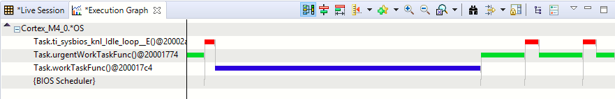
Let's look at the execution graph again.
Changing priority
Let's just change the workTaskParams.priority from 1 to 3 and rebuild/reload/run again.
    workTaskParams.priority = 3;
    workTaskParams.stack = &urgentWorkTaskStack;

    Task_construct(&urgentWorkTask, urgentWorkTaskFunc, &workTaskParams, NULL);
The "urgent" LED1 is now flashing at the desired rate (because it's a higher priority task now).
Additional Resources
Additional training and reference material for TI-RTOS is available in the following places:
SimpleLink Academy
Online
This work is licensed under a Creative Commons Attribution-NonCommercial-NoDerivatives 4.0 International License.