Introduction
TI 15.4-Stack is an IEEE 802.15.4e/g RF communication stack. It is a main part of the SimpleLink Software Development Kits (SDK), and provides support for star-topology networks for a Sub-1GHz application or a 2.4GHz application. TI 15.4-Stack runs on MCUs from TI's SimpleLink microcontroller (MCU) family of devices. The Sub-1 GHz implementation offers several key benefits such as longer range in FCC band and better protection against in-band interference by implementing frequency hopping, as well as the ability to send 2.4GHz BLE beacon packets while operating on a Sub-1GHz TI 15.4-Stack network when using dual-band mode on the CC1352. This complete stack offering provides an accelerated time to market with a complete end-to-end node-to-gateway solution.
In this lab, we will run a pair of examples based on the complete TI 15.4-Stack, one Sensor and one Collector - creating a star network of sensor node(s) sending data to a collector.
- The Collector Example Application implements the PAN-Coordinator, or the central node in the network. This application starts the network, allows devices to join the network, and configures the joining devices on how often to report the sensor data. It then sends periodic tracking request messages (to which it expects tracking response messages) to determine whether or not the sensor nodes are alive in the network.
- The Sensor Example Application implements the networked device, which joins the network started by the Collector. The Sensor periodically sends sensor data reports at the report interval configured by the Collector and responds to the tracking messages it receives.
The purpose of this lab is to familiarize the reader with the TI 15.4-Stack and with tools such as Code Composer Studio, by importing existing examples into the IDE. The lab contain several tasks:
Task 1: Building and loading the collector example
Task 2: Building and loading the sensor example
Task 3: Using the Collector and Sensor
Task 4: Updating the sensor's reporting rate
Further reading
This lab is the recommended first step for getting started with the TI 15.4-Stack, it is intended to teach you to quickly bring up a working network. As such, many useful features in TI 15.4-Stack are not discussed here. To learn more about features such as beacon vs. non-beacon mode, frequency hopping and more, please see the TI 15.4-Stack User's Guide
Technical support
For any questions you may have, please consult the relevant E2E forum - TI Sub-1 GHz E2E Forum.
Supported Devices/SDKs
This lab is intended to be used with the newest SDKs for each of these TI devices:
| TI Device | SDK |
|---|---|
| CC13x0 | SIMPLELINK-CC13X0-SDK |
| CC13x2 & CC26x2 | SIMPLELINK-CC13X2-26X2-SDK |
SysConfig support
This SimpleLink Academy lab supports both devices with (CC13x2 and CC26x2 devices) and without (CC13x0 devices) SysConfig. Please note instructions are sometimes divided in two in the following way.
Here are instructions for using SysConfig.
Here are instructions for when you're not using SysConfig.
Prerequisites
Background
- Basic TI-RTOS and CCS knowledge
- Some basic familiarity with embedded programming.
Software
- Code Composer Studio. Make sure your version of CCS is supported by the SimpleLink SDK you are using. You can find supported CCS versions in the SDK release notes.
- The corresponding SDK(s) from the list above
- Tera term or any equivalent terminal program
Hardware
- 2 x Compatible LaunchPads, refer to the Supported Devices/SDKs section
- 2 x USB Cables
Note
- These labs were done using CC13x2 LaunchPads and the CC13x2_CC26x2 SDK, though the procedure should be the same for every supported platform.
- Some screenshots in this lab may have been taken with an older version of the respective SDK or tool, so your actual screen may look a bit different, however the functionality and overall look and feel should be the same.
Group training additional requirements
Channel allocation
If you are part of a group training, the instructor should give each student a unique number. In this lab, each student uses a designated channel matching their student number: Student #1 should use channel 1, Student #2 should use channel 2, and so on.
Make sure to always use your designated channel, to avoid interfering with other students' operations.
Task 0: Label your LaunchPads
Label each of your LaunchPads with its XDS Device ID, as described here.
Additionally, label one LaunchPad as "Sensor" and the other as "Collector". These labels will be referred to throughout this lab. It is recommended to use a non-permanent marking for this (e.g. sticky notes), as these labels may only be relevant for this specific lab.
Task 1: Building and loading the collector example
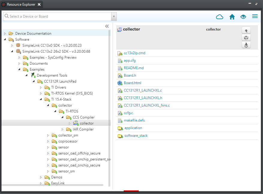
In CCS, open the resource explorer (view → Resource Explorer)
Expand the folders and select as in the following capture, then click Import To IDE: (Note: make sure to select the appropriate collector project for your platform. E.g. if you are using CC2652, select the CC2652 collector project in the CC13x2/CC26x2 SDK)
Update the target of the collector project to associate it with the "Collector" LaunchPad - as explained here.
If you are using a 2.4GHz project, skip to step 6. Otherwise update the radio settings as explained below.
Selecting the right PHY
The regulations in different parts of the world require the use of different frequency bands. A rough version is:
- 915 MHz in the US
- 868 MHz in Europe
- 433 MHz in China
For each of the frequency bands above, TI 15.4-Stack provides selection between operation modes:
- A faster default mode (50kbps data rate)
- LRM - long-range mode (5kbps data rate over a longer range)
- A high speed mode (200kbps data rate)
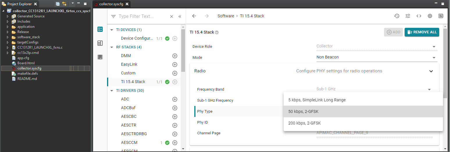
For this lab, please select the 50 kbps mode of the required frequency band. After finishing the official lab content, you may also experiment with the other modes.
Updating the channel mask
The stack can be configured to enable any of the supported channels. If more than one channel is enabled, the best ("most quiet") channel is selected by the collector when starting the network. When the sensor looks for a network to join, it scans all the enabled channels until it finds the collector.
In a group, each student should update their channel map such that only their designated channel is enabled, and all other channels are disabled.
Note that the number of supported channels may be limited, depending on the frequency band being used. Please make sure to select a channel within the supported range - see the note box below.
Available channels
- The number of supported channels depend on the selected frequency band:
- 2.4 GHz band - channels 11 to 26 - total of 16 channels
- 915 MHz band - channels 0 to 128 - total of 129 channels
- 868 MHz band - channels 0 to 33 - total of 34 channels
- 433 MHz band - channels 0 to 6 - total of 7 channels
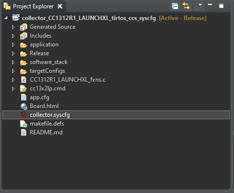
Locate the file collector.syscfg in the project explorer, and open it by double-clicking it.
You are responsible to select the right PHY, according to the region of operation and the desired range. This is done by modifying the value of Sub-1 Ghz frequency under the Radio Tab with one of the values from the drop down list.
To enabled the required channel and disable the other channels, you will need to edit the channel mask definition under the Network Settings in the collector.syscfg file. This configuration item is a bitmask representing all the available channels, this is represented as a drop down menu and you can select the channels you want transmit on by checking the box.
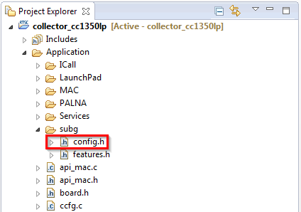
Locate the file config.h in the project explorer, and open it by double-clicking
You are responsible to select the right PHY, according to the region of operation and the desired range. This is done by modifying the value of
CONFIG_PHY_ID(defined in config.h) with one of the supported values fromapi_mac.h(see code snippets below)./*! Setting for Phy ID */ #define CONFIG_PHY_ID (APIMAC_STD_US_915_PHY_1)Example from config.h: by default, the US-compatible PHY is selected
   /*! PHY IDs - 915MHz US Frequency band operating mode # 1 */
   #define APIMAC_STD_US_915_PHY_1                 1
   /*! 863MHz ETSI Frequency band operating mode #1 */
   #define APIMAC_STD_ETSI_863_PHY_3               3
    /*! 433MHz China Frequency band operating mode #1 */
   #define APIMAC_GENERIC_CHINA_433_PHY_128        128
    /*! PHY IDs - 915MHz LRM US Frequency band operating mode # 1 */
   #define APIMAC_GENERIC_US_LRM_915_PHY_129       129
    /*! 433MHz China LRM Frequency band operating mode #1 */
   #define APIMAC_GENERIC_CHINA_LRM_433_PHY_130    130
    /*! 863MHz ETSI LRM Frequency band operating mode #1 */
   #define APIMAC_GENERIC_ETSI_LRM_863_PHY_131     131
   /*! PHY IDs - 915MHz US Frequency band operating mode # 3 */
  #define APIMAC_GENERIC_US_915_PHY_132            132
   /*! 863MHz ETSI Frequency band operating mode #2 */
  #define APIMAC_GENERIC_ETSI_863_PHY_133          133
The available PHY options are defined in api_mac.h. Note that the 868 MHz Band in the code is referred to as 863 MHz, named after the lowest supported frequency rather than the band's middle frequency.
To enable the required channel and disable the other channels, you will need to edit the CONFIG_CHANNEL_MASK definition in config.h. This configuration item is a bitmask representing all the available channels. For example, in the 915 MHz band, there are 129 channels available. The first byte in CONFIG_CHANNEL_MASK represents channels 0 to 7, the second byte represents channels 8 to 15, and so on. The last byte corresponds to channels 128 to 135 - but in this case, only bit 0 represents an actual channel (128), while the upper 7 bits are ignored.
Each student should update the definition of this configuration item such that only its designated channel is enabled, and all other channels are disabled. For example, student #10 should have it defined as follows:
  #define CONFIG_CHANNEL_MASK { 0x00, 0x04, 0x00, 0x00, 0x00, 0x00, \
                                  0x00, 0x00, 0x00, 0x00, 0x00, 0x00, \
                                  0x00, 0x00, 0x00, 0x00, 0x00 }
Student #10 channel configuration (enable channel 10, disable all other channels)
Multiple ways to prevent conflicts
In this lab, each student uses a different channel in order to avoid conflicts. Using TI 15.4-Stack, there is another way to avoid conflicts, which allows using the same channels by everybody. This method involves pre-assigning the same PAN-ID to every device in the intended network, and different PAN-IDs to different networks. The stack will automatically filter and accept only the packets targeted for its PAN. The downside of this would be that in a large classroom with many setups this could lead to channel congestion and a high rate of dropped packets.
Connect the "Collector" LaunchPad to the PC
Build the project and download it to the LaunchPad by selecting the collector project in the project explorer and clicking the green bug (or hitting F11)
When programming is finished, terminate the debug session by clicking the red square (or, select Run→Terminate).
Troubleshooting: CCS says source file could not be found
Sometimes, after closing and then reopening CCS, it may display an error message saying a source file could not be found, and request you to hit F5 to refresh. Simply pressing F5 does not work. To clear this error message and solve the issue, you need to right click on the containing folder in the project explorer (e.g. the folder "Application"), and select Refresh.
Task 2: Building and loading the sensor example
Repeat Task 1, but this time select the sensor project when importing and building and use the "Sensor" LaunchPad.
Update the Channel Mask!
Make sure you did not forget to change the radio settings and the channel mask for the sensor project as well.
Task 3: Using the Collector and Sensor
Close CCS
Make sure no terminal program is running.
Disconnect, then reconnect both LaunchPads to your PC. Otherwise, the LaunchPads' Application UART may not be available.
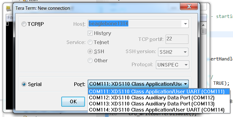
Open two instances of the terminal program. Connect each to a different LaunchPad's COM port - these ports should have the word 'UART' in their names. For example, in the following image, the you should select COM111 and COM114:
Configure the UARTs as follows:
- Baud rate: 115200
- Data: 8 bit
- Parity: none
- Stop: 1 bit
- Flow control: none.
Reset each of the LaunchPads to Factory New state by pressing and holding BTN-2, and then pressing the Reset button (while BTN-2 is held down).
Observe and Understand
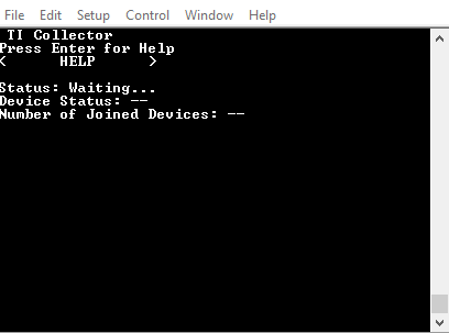
- The collector terminal should look like this:
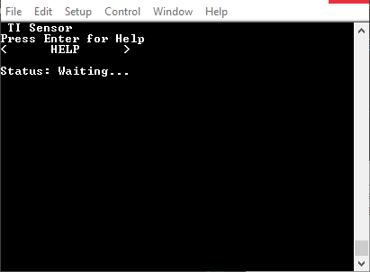
- The sensor terminal like this:
- The collector terminal should look like this:
Press BTN-1 on the collector to start the network, the red LED on the collector should turn on after a short while, and the LEDs on the sensor should both remain off. The red LED on the collector means that it has successfully created a network. The collector terminal will now also say "Started--Mode=NBCN, Addr=0xaabb, PanId=0x0001, Ch=x, PermitJoin=Off", where x will be the number of the actual channel that was selected.
Press BTN-2 on the collector to allow new devices to join the network. The red LED will start blinking, meaning that the network is now open for joining, and the collector's terminal will say "PermitJoin=On".
Press BTN-1 on the sensor to start looking for a network to connect to.
Observe and Understand
The sensor will join the network after a short while, indicated by the sensor red LED turning on (otherwise, see Troubleshooting below). The collector's terminal will say "Joined: 0xX" where 0xX is the sensor ID, and the sensor's terminal will say "Status: Joined--Mode=NBCN, Addr=0xX, PanId=0x0001, Ch=x" (0xX is the sensor ID), indicating successful network connection.
Troubleshooting
If the sensor does not join after a short while, please reset it using the reset button.
To close the network from allowing new devices to join, press the collector's BTN-2 again. The collector red LED will stop blinking and remain on.
Observe and Understand
- The Collector's terminal will say "Device Status: Sensor - Addr=0xX, Temp=x, RSSI=-x" when a reading is received from the sensor.
- Whenever a reading is sent from the sensor or received by the collector, the green LED will toggle on the sensor / collector respectively.
- Readings are sent from the sensor periodically. By default, the period configured by the collector is 3 seconds, but if the sensor fails to receive the configuration from the collector, it will send the readings every 3 seconds.
- Commands from the collector to the sensor can be sent only after the sensor is polling for data. These poll requests are sent by the sensor periodically, the sensor is allowed to sleep in the meantime. The default sensor poll rate is 2 seconds. This poll rate can be changed by the collector as part of the configuration message.
Toggle command: By pressing BTN-1 on the collector, you can toggle the red LED on the sensor. Try this a few times. Notice that the LED state may take up to 6 seconds to change, since the collector can only send the toggle command following a poll request from the sensor.
Using the toggle command when more than one sensor is connected
Note that if more than one sensor is connected to the same collector, the toggle command will only be sent to sensor #1 (the first to join the collector).
Task 4: Updating the sensor's reporting rate
Now let's make the reporting and the polling rate higher, to get a more responsive demo. All values below are in milliseconds.
Open CCS, using the same workspace you used before
Open collector.syscfg and sensor.syscfg, navigate to TI 15.4 Stack, open the Network settings and scroll down to the Application tab.
Update the reporting interval of the sensor: In sensor.syscfg set Reporting Interval(ms) to 1500 (instead of 3000). (Do not change the polling interval in this file.)
Update the reporting interval that the collector will request from the sensor: In collector.syscfg, set Reporting Interval to 1500 (instead of 3000)
In the same file, Update the polling interval that the collector will request from the sensor - set CONFIG_POLLING_INTERVAL to 1000 (instead of 2000)
Update the reporting interval of the sensor: In the sensor project, in config.h, set CONFIG_REPORTING_INTERVAL to 500 (instead of 180000)
Update the reporting interval that the collector will request from the sensor: In the collector project, in config.h, set CONFIG_REPORTING_INTERVAL to 1000 (instead of 90000)
In the same file, Update the polling interval that the collector will request from the sensor - set CONFIG_POLLING_INTERVAL to 100 (instead of 6000)
Sensor default polling interval
The default polling interval (that is in effect in the sensor until configured otherwise by the collector) is defined by CONFIG_POLLING_INTERVAL in sensor config.h (default is 2000). Don't change this value.
Rebuild the collector and sensor projects, and program the LaunchPads with the new builds, by following the next steps for each of the two projects:
- Select the project in Project Explorer
- Build and download to target by clicking the green bug icon
- Stop the debug session by clicking the red square icon once it becomes available
Reset both devices to Factory New (press the Reset button while holding BTN-2) and have the sensor connect to the collector as explained in the previous task.
Observe and Understand
See how the changes you made affect the sensor operation:
- As soon as the sensor connects to the network, the reporting rate is 1500 ms.
- After about 2 seconds, the sensor polls for data and the configuration message is sent from the collector.
- Reporting rate is changed to 1 second.
- After a few more seconds, when the existing polling timer expires, the polling rate is increased to 1000 ms - as evident by the high responsiveness of the sensor's red LED when pressing the collector's BTN-1 (i.e when sending the Toggle command).
References
TI 15.4-Stack User's Guide – Available here.
TI Sub-1 GHz E2E Forum – TI Sub-1 GHz E2E Forum
CC13xx/CC26xx Software Overview – Available at https://www.ti.com/tool/cc13xx-sw and https://www.ti.com/tool/SIMPLELINK-CC13X2-26X2-SDK.
CC13x0 Technical Reference Manual – Available here
CC13x2/CC26x2 Technical Reference Manual – Available here
This work is licensed under a Creative Commons Attribution-NonCommercial-NoDerivatives 4.0 International License.