Introduction
This workshop is an introduction to the Bluetooth® Mesh part of the SimpleLink™ CC26x2 and CC13x2 Software Development Kits (SDK). The 4 tasks in this lab session are targeted to be completed within a 2.5-hour time frame. An intermediate level of knowledge of the C programming language and some experience with embedded software development is needed to be able to complete the tasks.
This lab session uses the SimpleLink™ CC26X2R1 wireless MCU LaunchPad development kit to demonstrate the tasks in this module. The first task shows how to download a project to the device and run it, and the subsequent tasks will explore various configurations of a Bluetooth mesh node and make some small changes to the mesh application. This lab will only focus on the configuration of a single mesh node. To simplify, this lab will statically provision nodes to a mesh network with preconfigured device addresses and application keys.
Kit and SDK compatibility
Multiple of the CC13x2 and CC26x2 development kits support Bluetooth Low Energy operation. See the Hardware Requirement for details. In this lab we will use the CC26x2R Launchpad as an example.
Prerequisites
Hardware
For this lab, you need a minimum of two or more Bluetooth-enabled development boards. Supported development boards for Bluetooth Mesh are:
Software
- CCS 10.3 or IAR 8.50.9 installed with support for CC13xx/CC26xx devices.
- SimpleLink™ CC13x2 and CC26x2 SDK 5.10
Recommended reading
- README.html file located at:
simplelink_cc13x2_26x2_sdk\examples\rtos\CC26X2R1_LAUNCHXL\ble5stack\simple_mesh_nodesimplelink_cc13x2_26x2_sdk\examples\rtos\CC1352P_2_LAUNCHXL\ble5stack\simple_mesh_node
- TI BLE5-Stack Quick Start
- Bluetooth Mesh Chapter of the TI BLE5-Stack User's Guide
- Zephyr Mesh Documentation
Background
Bluetooth Mesh is standardized by the Bluetooth SIG in the Bluetooth Mesh Specification and defines fundamental requirements to enable an interoperable mesh networking solution for Bluetooth Low Energy (BLE) wireless technology. For a full description of TI's Bluetooth Mesh solution, please refer to the TI Bluetooth Mesh section of the TI BLE5-Stack User's Guide.
Mesh Network Basics
A mesh network is a network topology where each node may send a message to any node on the network. A Bluetooth mesh node communicates to a mesh network using BLE advertisements. The Bluetooth Mesh Specification defines many standardized mesh models that you can use to create your mesh product. For example, the spec defines models targeted specifically for lighting , sensor control, and a suite of generic models that one can use to make a mesh node for your application. Models are used to implement standardized functionality (if using SIG defined Models) for a particular end node. End nodes can really be anything: a light bulb, a switch, a speaker, etc. This tutorial describes how to configure a mesh node for your application using Texas Instruments' Bluetooth Mesh solution. It is meant to be a start to your mesh development, and will only cover the configuration of a single node. When a mesh network is designed, it usually consists of multiple nodes. You may use this tutorial to configure multiple nodes in your network, however, the topology of your network (i.e. how many nodes, network layout, number of friend/relay/proxy nodes, how each node communicates at what interval, etc) is entirely up to you to decide.
Mesh Node Types
Before configuring a Bluetooth mesh node, the node type must be selected. As defined by the Bluetooth SIG, the following node types are supported:
| Node Type | Description |
|---|---|
| Basic | Includes basic node functionality for receiving and processing broadcast, multicast and unicast messages designated for the node as well as transmission of local mesh data |
| Relay | Basic node features as well as mesh message relaying for range extension within a mesh network (Multiple hops supported) |
| Proxy | Proxying between GATT-Bearer and Advertise bearer. This allows transmission to devices that support GATT-bearer only (e.g. mobiles phones) |
| Low Power | A power limited node which wakes up on specific time intervals to send messages or receive messages which are aggregated by a designated friend node. |
| Friend | Used to aggregate messages for LPN during their sleep cycles and deliver their messages upon wake-up |
Which node type enables provides extended range in a mesh network?
Mesh Node Composition Data
Each mesh node has composition data which contains information about the node. This data consists of the node's address, addresses the node subscribes to and elements the node has defined. An element is an addressable entity within a node. Each node has at least one element, the primary element, and may have one or more additional secondary elements.
Within each element is a model. A model defines the basic functionality of a node by defining the required states, the messages that act upon those states, and any associated behavior. Foundation configuration and health server models are mandatory in every node.
Below is a brief look at a typical mesh node and its element, model, and state information.
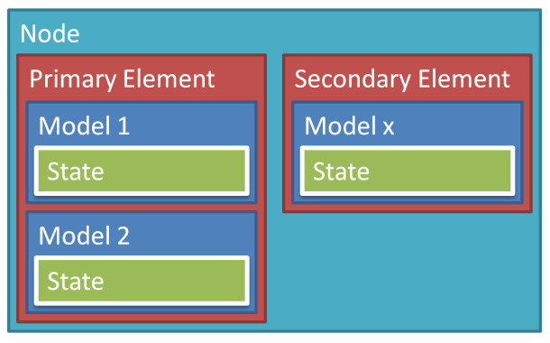
To recap:
- Node: One device
- Element: Addressable entity in the network
- Model: Implements functionality
- State: Contains the condition of a model
For more information, refer to Section 2.3 Architectural concepts section of the Mesh Profile Bluetooth Mesh Specification.
Getting started – Desktop
At the end of this module you must have:
- SimpleLink™ CC13X2-26X2 SDK installed
- A basic knowledge of the capabilities of a Bluetooth Mesh node
- A basic knowledge of how to add and configure a Bluetooth Mesh node
Install the Software
If not already done, download the SimpleLink™ CC13X2-26X2 SDK shown in the section Prerequisites above.
Run the SimpleLink™ SDK installer. This gives you the SDK with TI-RTOS included at the default location:
C:\ti\simplelink_cc13x2_26x2_sdk_x_xx_xx_xx
Task 1 - Run the simple_mesh_node project
Configure the node using SysConfig
Open CCS 10.2.
Import the simple_mesh_node example from:
simplelink_cc13x2_26x2_sdk\examples\rtos\CC26X2R1_LAUNCHXL\ble5stack\simple_mesh_nodeOpen the
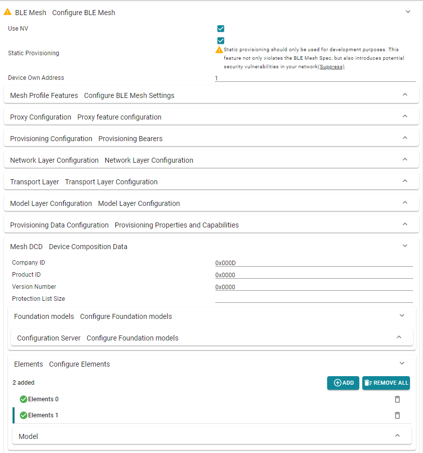
simple_mesh_node.syscfgfile to configure the node.Enable Static Provisioning under the BLE Mesh section of the BLE configuration SysConfig tab. Once selected, the Device Own Address field will appear. Here, configure the node's unique "Own Address"
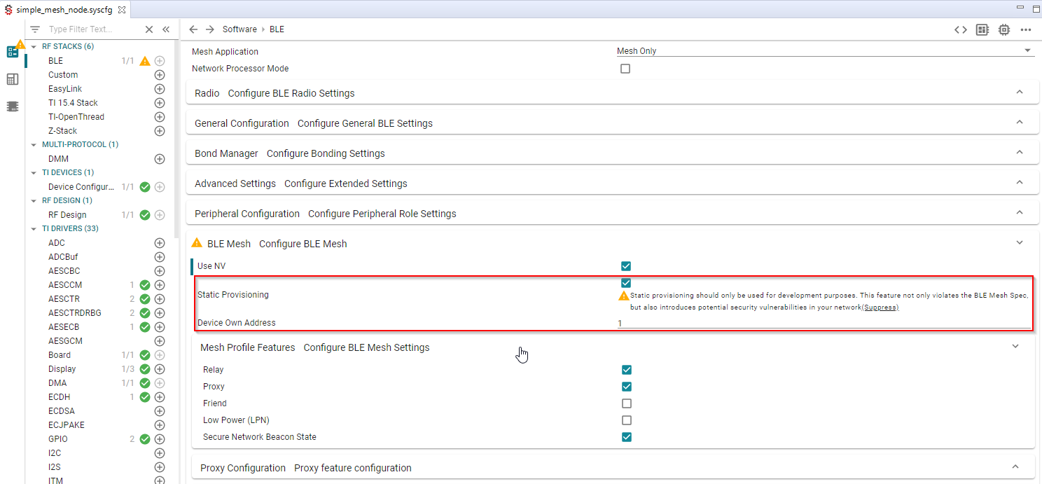
Static Provisioning
By default, Static Provisioning is disabled. A mesh node requires a provisioning client to be added to a mesh network. For the simplicity of this guide we use Static Provisioning, which skips the provisioning process and uses pre-programmed mesh network data like device keys, device addresses, etc. This should only be used for quick mesh network evaluation and for debug purposes where a provisioner is not necessary. Checking this box will result in a warning triggered by SysConfig.
Open the Mesh Profile Features section to select the node type, as shown in the picture above. By default, Relay and Proxy modes are selected. For this training, we will use the default selected node types.
Selecting appropriate nodes for your network
In general, there are no limitations around selection of node types in your network. A node can support multiple types (i.e. be a Friend and a Relay). A network can consist of any combination of supported nodes, however, there is one thing to keep in mind:
- Low Power Nodes (LPNs) cannot exist without a Friend node, as LPNs wake up periodically to receive messages that are cached by the Friend node. You can have more than one LPNs per Friend node. Here, care must be taken to ensure the Friend node has enough memory available to cache messages for its LPNs.
Build the Projects and Flash the Device
simple_mesh_node_CC26X2R1_LAUNCHXL_tirtos_ccs
- Build the
simple_mesh_node_CC26X2R1_LAUNCHXL_tirtos_ccsproject by right-clicking on it and selecting Build Project. - Download and run the project by either
- Right clicking on it and selecting Debug As → Code Composer Debug Session, or
- Pressing F11 when the project is marked as active (see image above)
- Clicking the green bug icon in the toolbar
- When the project is downloaded and halted at
main(), press F8 or the Play/Pause button to start executing the code.
After the application runs you should observe something like the following in your terminal application:

The status lines shown above (i.e. BTN OFF, LED OFF, etc) update whenever a message is sent or received to/from the network. For more information about the menu, refer to the project's README.
Use the two-button menu to initialize the device
Under default conditions, this step does not need to be performed. This is because a mesh provisioning client performs the necessary initializations by providing the node with its security keys and device address. However, if you recall, we enabled Static Provisioning in the previous step. For this reason, we must initialize the device.
Navigate to MESH INIT menu
Select MeshInit & static provisioning
After performing step 2, you should see following in your serial terminal:
Add more nodes to the network
After all, a mesh network cannot be called a network without multiple nodes!
Repeat the above steps to generate a new hex file, making sure to change the Device's Own Address to a unique, unused address. You can do so for up to 32767 nodes, as defined in Bluetooth Mesh Specification. For now, we'll stick to 2 nodes. We'll give the first node an Own Address of 1. The second node will be given an Own Address of 2.
Get familiar with the menu
Try navigating to the MESH BUTTON menu and turning on/off the LEDs of each mesh node in the network. This will give you a sneak peek at our next Task!
The LEDs on the LaunchPads are not configured and won't turn on.
Check the serial terminal for a change in the LED status instead!
Task 2 - Analyze mesh composition data
In this task, we'll take a finer look at the code that enables the functionality
shown in the default simple_mesh_node example. This will include a look at
the node's composition data and how SysConfig enables you to quickly add models
and elements as you see fit.
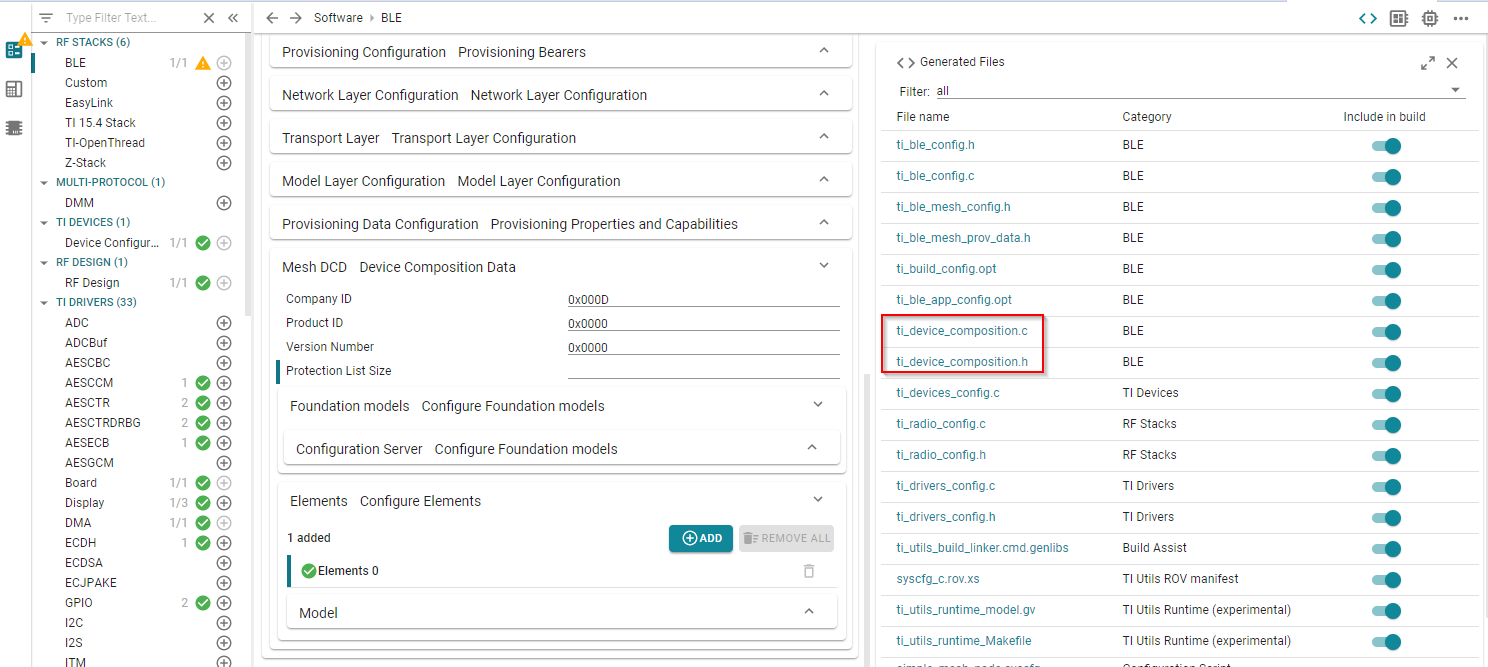
Take a look at the SysConfig module and find the generated composition data.
This is stored in ti_device_composition.c/h, as shown below.
After opening up the file, let us walk through the various structures defined.
Note: All of the following code is automatically generated by SysConfig.
SysConfig generated files should not be modified (i.e.
ti_device_composition.c) directly as the SysConfig tool will overwrite your
changes. Be sure to use the SysConfig GUI to configure your mesh node.
Composition Data
Device composition data contains information about the node, the elements it contains and the models and features it supports.
At the bottom of ti_device_composition.c, you'll find the struct that holds
the device's composition data:
const struct bt_mesh_comp comp = {
    .cid = 0xD,
    .elem = elements,
    .elem_count = ARRAY_SIZE(elements),
};
ti_device_composition.c – Send the built messageMesh Node Composition Data
Elements
The default example defines a single element. At the
bottom of ti_device_composition.c, you'll find the element initialization:
/*======================Elements======================
*/
struct bt_mesh_elem elements[] = {
    BT_MESH_ELEM(0, root_models, vnd_models0),

};
/*
*======================Elements End======================
*/
ti_device_composition.c – Mesh Node Elements
Above, BT_MESH_ELEM is a helper macro to define a mesh element within an array. For more information, navigate to Mesh> → zephyr → include → bluetooth → mesh → access.h. You can also refer to the Zephyr Mesh Documentation.
Next, we'll go over the various contents of this element (i.e. models).
Foundation Models
Mesh nodes are required to support mandatory Foundation models to enable
configuration and health of each node. For this reason, we find the first
required Configuration Server Model below inside ti_device_composition.c. This
struct contains information about the supported features, time-to-live (used to
manage message "flooding"), and heartbeat message parameters (used to indicate
the node is still alive and active). For more
information about the Configuration Server Model, refer to Section 4.4.1 of the
Profile Bluetooth Mesh Specification.
struct bt_mesh_cfg_srv cfg_srv = {
    .relay = BT_MESH_RELAY_ENABLED,
    .beacon = BT_MESH_BEACON_ENABLED,
    .gatt_proxy = BT_MESH_GATT_PROXY_ENABLED,
    .frnd = BT_MESH_FRIEND_NOT_SUPPORTED,
    .default_ttl = 7,
    /* 2 transmissions with 20ms interval */
    .net_transmit = BT_MESH_TRANSMIT(2, 20),
    /* 3 transmissions with 20ms interval */
    .relay_retransmit = BT_MESH_TRANSMIT(3, 20),
    .hb_sub.func = heartbeat,

};
ti_device_composition.c – Configuration Server Model Struct
The second required model is the Health Server model. This model is used for reporting faults and handling diagnostic information for a node. For more information about this, refer to Section 4.4.3 of the Profile Bluetooth Mesh Specification.
Vendor Models
The next set of models available in the default simple_mesh_node example is a
vendor model. Vendor models are models defined by vendors, i.e. these are custom
models that are not defined by the Bluetooth SIG. Here, you can specify
different message types, each given a particular opcode, as well as a callback
that the Mesh Stack will trigger when a message with a valid opcode is received.
In our default example, when the user navigates to the MESH BUTTON menu and
toggles an LED, the application will send a message to the Group address. When
any node that subscribes to this Group address receives this message, the
vnd_button_pressed_cb will be triggered. Below shows the message types
defined by the default application.
struct bt_mesh_model_op vnd_ops_0_0[] = {
    { BT_MESH_MODEL_OP_3(0x0,0xD ), 0  , vnd_button_pressed_cb },
    { BT_MESH_MODEL_OP_3(0x1,0xD ), 0  , vnd_get_status_cb },
    { BT_MESH_MODEL_OP_3(0x2,0xD ), 0  , vnd_notify_status_cb },
    BT_MESH_MODEL_OP_END,
};
ti_device_composition.c – Vendor Model Struct
Bluetooth Mesh Operation Codes
BT_MESH_MODEL_OP_3() is a macro that formats opcodes as defined in the Bluetooth Mesh Specification. See Section 3.7.3.1 of the Profile specification for more information.
Since we are using a vendor specific opcode, we must define a 3-octet opcode. Similar macro's are defined for 1 and 2-octet opcodes (i.e. BT_MESH_MODEL_OP_1, BT_MESH_MODEL_OP_2). These are defined at Mesh → zephyr → include → bluetooth → mesh → access.h
Bluetooth SIG defined Models
The default application supports several models defined by the Bluetooth SIG. For detailed information about each SIG defined model, refer to the Model Bluetooth Mesh Specification.
The following set of models defined in the ti_device_composition.c file are
the Bluetooth SIG defined models. The default example includes the following
models: Generic OnOff Server/Client, Generic Level Server/Client, Generic
Default Transition Time Server/Client, Generic OnPowerUp Server/Client, and
Generic Battery Server/Client. Additionally, Sensor Server/Client and Sensor
Setup models are supported. The above models are defined in the following
struct:
struct bt_mesh_model root_models[] = {
    BT_MESH_MODEL_CFG_SRV(&cfg_srv),
    BT_MESH_MODEL_CFG_CLI(&cfg_cli),
    BT_MESH_MODEL_HEALTH_SRV(&health_srv_0, &health_srv_pub_root),
    BT_MESH_MODEL(BT_MESH_MODEL_ID_GEN_ONOFF_SRV,
    .
    .
    .
};
ti_device_composition.c – Bluetooth SIG defined models
Task 3 - Sending mesh messages
This task will use the simple_mesh_node example's two button menu to show how
messages are sent to the mesh network. For simplicity, let's take a look at the
MESH BUTTON menu.
- Navigate to
simple_mesh_node_menu.c Locate the MESH BUTTON menu object and corresponding menu actions.
- Following the menu logic, we arrive at the following user defined application
function:
MeshApp_button_pressed()
Let's take a look at this function.
First, we need to find the model we'd like to use to tie the message to.
  struct bt_mesh_model *pModel;
  .
  .
  .
  pModel = bt_mesh_model_find_vnd(&comp.elem[SAMPLE_APP_MODELS_ELEMENT], BT_COMP_ID, 0);
  if (pModel == NULL)
  {
      Display_printf(dispHandle, SMN_ROW_NTFY_ST, 0, "The vnd model doesn't exist in the comp data, add it in order to send this msg");
      return -1;
  }
simple_mesh_node.c::MeshApp_button_pressed() – Find the vendor model to use for this message
We also need to give the recipient of the message additional information, to use to decrypt the packet (i.e. an application key index), a target destination address, and a time to live (TTL) setting. TTL is used to give the message a "lifespan". It limits the number of times a message can be relayed (i.e. # of hops). This prevents the network from being flooded with outdated messages.
  struct bt_mesh_msg_ctx ctx = {
          .app_idx = app_idx, //pass in the appkey index
          .addr = mesh_btn_target_addr, //set a target destination address
          .send_ttl = BT_MESH_TTL_DEFAULT, //include TTL information
  };
simple_mesh_node.c::MeshApp_button_pressed() – Pass in necessary metadata to the message
Finally, we're ready to build our message. Below, you'll find a buffer is
allocated and initialized. The message is initialized with the appropriate
OPCODE that was defined earlier in ti_device_composition.c. Once that's done,
we pass in the data to our message buffer and send it off to the stack. The mesh
stack will then send this message to the mesh network.
  NET_BUF_SIMPLE_DEFINE(msg, 3 + 5); //Allocate 3 bytes for the OPCODE, 4 bytes for the transMIC, and 1 byte for the message payload

  bt_mesh_model_msg_init(&msg, OP_VENDOR_BUTTON);    //use appropriate OPCODE
  net_buf_simple_add_u8(&msg, onoff_state);         //add custom message data
  if (bt_mesh_model_send(pModel, &ctx, &msg, NULL, NULL)) { //send the message
      return -1;
  }
simple_mesh_node.c::MeshApp_button_pressed() – Send the built message
Similar procedures are followed with the other SIG defined models. For more information about the message structure, refer to section 3.7.3 Access Payload in the Profile Bluetooth Mesh Specification.
For more information about this, refer to the Message Handling inside the BLE Mesh section of the TI BLE5-Stack User's Guide.
Task 4 - Adding elements and models
In this task, you will modify the `simple_mesh_node example to add an additional element and vendor model. For simplicity, we will modify the MESH BUTTON menu to use our new element and vendor model. The messages sent using the model can be anything, however in this task, let us treat this as a custom LED light bulb.
Add Elements and Models using SysConfig
- Navigate to the SysConfig tool by opening the
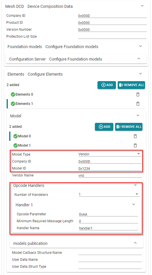
simple_mesh_node.syscfgfile in your project. - Navigate to BLE → BLE Mesh Configure BLE Mesh → Mesh DCD Device Composition Data → Elements Configure Elements directory within SysConfig.
- Hit the Add button to create another Element.
Next, open the Model dropdown menu and add a vendor model.
- This time, let us change the Model ID.
- Let's also add a callback handler for the new model, with a custom opcode. For this guide, let's use 0xAA.
- Change the Company ID to your assigned Company Identifier (see Bluetooth SIG website for more info)
Modify the Device Own Address
Warning!
As we statically provision the nodes in this network, care must be taken when assigning the device address for each node. As the SPEC defines, each element is an addressable entity with its own unicast address. Each element is assigned an addressed based off the Device Own Address. So, if there are 2 elements in Node #1, this means we must assign Node #2's Device Own Address to at least 3.
If static provisioning is not enabled, this is handled by the configuration client.
Modify the code
For simplicity, let us modify the existing MESH BUTTON menu and leverage the example. This way, we will send a message using our new element and model to the mesh network by simply selecting Turn LED ON .
See the comments below to modify the menu function accordingly.
 /* Add the following new OPCODE (0xAA) for our custom vendor model */
 #define OP_VENDOR_CUSTOM BT_MESH_MODEL_OP_3(0xAA, CONFIG_BT_COMPANY_ID)

 int MeshApp_button_pressed(uint8_t onoff_state)
 {
   struct bt_mesh_model *pModel;
   NET_BUF_SIMPLE_DEFINE(msg, 3 + 5);

   struct bt_mesh_msg_ctx ctx = {
           .app_idx = app_idx,
           .addr = mesh_btn_target_addr,
           .send_ttl = BT_MESH_TTL_DEFAULT,
   };

 /* MODIFY THIS LINE */
   pModel = bt_mesh_model_find_vnd(&comp.elem[1], BT_COMP_ID, 0x1234); //pass in element index: 1, and a new Model ID: 0x1234
 /* MODIFY LINE END */
   if (pModel == NULL)
   {
       Display_printf(dispHandle, SMN_ROW_NTFY_ST, 0, "The vnd model doesn't exist in the comp data, add it in order to send this msg");
       return -1;
   }
 /* MODIFY THIS LINE*/
   bt_mesh_model_msg_init(&msg, OP_VENDOR_CUSTOM); //pass in custom opcode
 /* MODIFY LINE END */
   net_buf_simple_add_u8(&msg, onoff_state);
   if (bt_mesh_model_send(pModel, &ctx, &msg, NULL, NULL)) {
       Display_printf(dispHandle, SMN_ROW_NTFY_ST, 0, "Msg error code: 0x%x", ret);
       return -1;
   }

   return 0;
 }
simple_mesh_node.c::MeshApp_button_pressed()** – Modify function to use our new element/model
Add the callback function to
simple_mesh_node.c. This handler function will be called when a message is received with the above OPCODE.void handler1(struct bt_mesh_model *model,struct bt_mesh_msg_ctx *ctx, struct net_buf_simple *buf) { uint8_t msg; // get message contents from the stack msg = net_buf_simple_pull_u8(buf); // check own address if (ctx->addr == mesh_own_addr) { return; } #ifdef USE_APP_MENU // Handle the message Display_printf(dispHandle, SMN_ROW_MESH_CB, 0, "MESH CBK: CUSTOM VENDOR callback from addr=0x%x", ctx->addr); #endif }simple_mesh_node.c::handler1()** – Add handler1() to process the message.
For nodes to send/receive messages, models need to be binded with an application encryption key. This process is normally done using a Configuration Client (i.e. cell phone). However, since we enabled Static Provisioning, we must add the necessary bindings to the node. The following should be added to
static_prov.c::MeshApp_provConfigure()./* Bind to vendor model bt_mesh_cfg_mod_app_bind_vnd Input Parameter Deep-dive net_idx: Pass in the network index addr: Address of the node elem_addr: Address of the element of the node. Here we refer to the second element, so we add 1. mod_app_idx: Application Key Index mod_id: Model ID. Here we set 0x1234 to match our Model ID in SysConfig. cid: Company ID status: Not needed */ bt_mesh_cfg_mod_app_bind_vnd(net_idx, addr, addr+1, app_idx, 0x1234, CONFIG_BT_COMPANY_ID, NULL);static_prov.c::MeshApp_provConfigure() –Bind the application key to the second element's vendor model.
Nodes must finally subscribe to specific addresses to receive messages sent to a group. Since the Turn LED ON menu item sends a message to a GROUP_ADDR, we must explicitly subscribe to the newly added model. The following should be added to
static_prov.c::MeshApp_provConfigure()./* Add model subscription */ bt_mesh_cfg_mod_sub_add_vnd(net_idx, addr, addr+1, GROUP_ADDR, 0x1234, CONFIG_BT_COMPANY_ID, NULL);static_prov.c::MeshApp_provConfigure() – Subscribe to the new model
That's it! You should now be able to see each node publish a message using the second element's vendor model to the GROUP_ADDR. Each node on the network should print "MESH CBK: CUSTOM VENDOR callback" to the UART terminal when it receives a message.
Debug the application
Not seeing the proper output? Most of the mesh API's return statuses that you can use to debug the application. Print those to the terminal to start debugging your application! Below is a quick example of how to do so for the bt_mesh_model_send() API:
  int ret = 0;
  if (ret = bt_mesh_model_send(pModel, &ctx, &msg, NULL, NULL)) {
      Display_printf(dispHandle, SMN_ROW_NTFY_ST, 0, "Msg error code: 0x%d", ret);
      return -1;
  }
Analyze the return code
Once you have the return code, follow code to the access layer where these return codes are available. Remember, Texas Instruments uses the Zephyr Project's Mesh open-source solution ported for SimpleLink™ devices. Use that to your advantage! This means you are welcome to read through the Zephyr Mesh Documentation which will provide more information about our Bluetooth Mesh solution.
References and Resources
Bluetooth Mesh Models Technical Overview
This work is licensed under a Creative Commons Attribution-NonCommercial-NoDerivatives 4.0 International License.