Introduction
TI 15.4-Stack is an IEEE 802.15.4e/g RF communication stack. It is a main part of the SimpleLink CC13x2_CC26x2 Software Development Kits (SDK), and provides support for star-topology networks for a Sub-1GHz application or a 2.4GHz application, depending on your selected device.
In this lab, we will run a pair of examples based on the complete TI 15.4-Stack, one Sensor and one Collector - creating a star network of sensor node(s) sending data to a collector.
The purpose of this lab is to familiarize the users with the TI 15.4-Stack and with performing Over the Air Downloads to the LPSTK. The lab contain several tasks:
Task 1: Modifying the collector example for the LaunchPad SensorTag Sensor data
Task 2: Programming the LPSTK-CC1352R with the 15.4 Sensor example using OAD
Task 3: Using the Collector and Sensor
Further reading
To learn more about TI-15.4 Stack features such as beacon vs. non-beacon mode, frequency hopping and more, please see docs\ti154stack\ti154stack-software-developers-guide.html, under the SDK installation folder.
You can also refer to the SimpleLink Academy module "Sensor and Collector - TI 15.4-Stack Project Zero" located in the TI 15.4-Stack folder
For more information about the LaunchPad SensorTag Kit, plese refer to the LPSTK Out-of-Box SimpleLink Academy Lab
Prerequisites
Software
- Code Composer Studio v9.2 or later
Make sure that CCS is using the latest updates: Help → Check for Updates - SIMPLELINK-CC13X2-26X2-SDK
- Tera term or any other equivalent terminal program
- The SimpleLink Starter smartphone application.
Hardware
- 1x LAUCHXL-CC1352R LaunchPad (to act as a collector for the network)
- 1 or more LPSTK-CC1352R (to act as sensors in the network)
Task 1: Building and loading the collector example
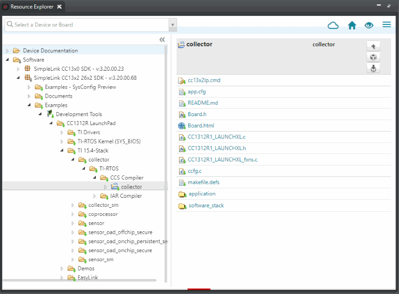
In CCS, open the resource explorer (view → Resource Explorer)
Expand the folders and select as in the following capture, then click Import To IDE: (Note: make sure to select the appropriate collector project for your platform. e.g. if you are using CC2652, select the CC2652 collector project in the CC26x2 SDK)
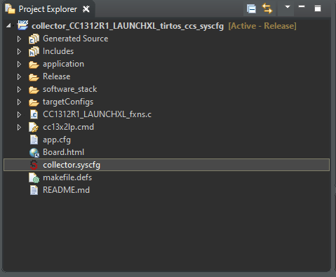
Locate the file collector.syscfg in the project explorer, and open it by double-clicking
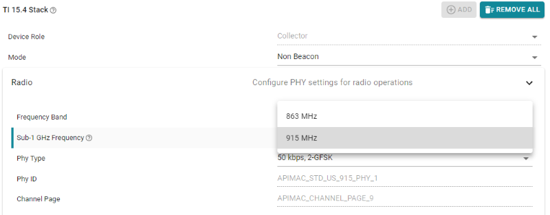
In the SysConfig view, click on "TI 15.4 Stack" under the "RF Stacks" category
Expand the "Radio" category, and select the appropriate Sub-1GHz Frequencey for your region
- The regulations in different parts of the world require the use of different frequency bands:
- 915 MHz in the US
- 863 MHz in Europe
- The regulations in different parts of the world require the use of different frequency bands:
Next, we need to modify the collector to print sensor values from the LPSTK. To do this, we will add additional serial terminal prints to the CSF file
Open the Colector Specific Functions file, located in
/application/collector/csf.cand replace lines 839 and 840CUI_statusLinePrintf(csfCuiHndl, deviceStatusLine, "Sensor - Addr=0x%04x, Temp=%d, RSSI=%d", pSrcAddr->addr.shortAddr, pMsg->tempSensor.ambienceTemp, rssi);csf.c, original code
with the following code
CUI_statusLinePrintf(csfCuiHndl, deviceStatusLine, "Sensor - Addr=0x%04x, Temp=%d, Humidity=%d, Light=%d, RSSI=%d", pSrcAddr->addr.shortAddr, pMsg->humiditySensor.temp, pMsg->humiditySensor.humidity, pMsg->lightSensor.rawData, rssi);csf.c, modified code
Connect the "Collector" LaunchPad to the PC
Build the project and download it to the LaunchPad by selecting the collector project in the project explorer and clicking the green bug (or hitting F11)
When programming is finished, terminate the debug session by clicking the red square (or, select Run→Terminate).
More info
For more information regarding the available configuration settings, please see docs\ti154stack\ti154stack-software-developers-guide.html, under the SDK installation folder.
Task 2: Loading the sensor example to the LPSTK
In this section we will use the OAD (Over the Air Download) feature of the mobile app to load the pre-built TI 15.4 Sensor example to your LPSTK. The Sensor project source code can be found in the CC13x2 CC16x2 SDK at \examples\rtos\CC1352R1_LAUNCHXL\dmm\dmm_154sensor_remote_display_oad_lpstk_app.
Make sure your LPSTK is in the Out of Box state. If not, hold down BTN-1 (left button) and toggle power on then off. On the next power-up, your LPSTK will revert to the Out-of-Box image.
Note
if you have flashed an image besides the 3 LPSTK examples in the mobile app, you may not be able to revert to the factory image. You will need to debug your LaunchPad SensorTag and re-program it with the Multi Sensor example. For more information, please refer to the LPSTK OOB SimpleLink Academy and the README for the
multi_sensorproject in the SDK.Alternatively, you can program the example project
dmm_154sensor_remote_display_oad_lpstk_appfound in the CC13x2 CC16x2 SDK in the folder\examples\rtos\CC1352R1_LAUNCHXL\dmm\Open the SimpleLink Starter App and select your LPSTK from the list of devices
Select Sensor View
Click "FW Download (Enhanced)"
Click "Select FW File"
From the list of Supported Factory Images, select "Sensor Node Example for LPSTK-CC1352R - US" or "Sensor Node Example for LPSTK-CC1352R - EU" depending on your reigon
Click "Program" on the next screen
After a successful download, toggle the power on your LaunchPad Sensor tag off, then on again
Task 3: Using the Collector and Sensor
Close CCS
Make sure no terminal program is running.
Disconnect, then reconnect the CC13x2 LaunchPad (Collector) to your PC. Otherwise, the LaunchPads' Application UART may not be available.
Open your terminal program and connect to your LaunchPad's COM port - this port should have the word 'UART' in the name.
Configure the UART as follows:
- Baud rate: 115200
- Data: 8 bit
- Parity: none
- Stop: 1 bit
- Flow control: none.
Reset the TI 15.4 settings on your by pressing and holding BTN-2, and then pressing the Reset button (while Btn-2 is held down).
- The collector terminal should look like this:
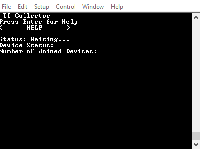
- The collector terminal should look like this:
Press BTN-1 on the collector to start the network, the red LED on the collector should turn on after a short while, and the LEDs on the sensor should both remain off. The red LED on the collector means that it have successfully created a network. The collector terminal will now also say
"Started--Mode=NBCN, Addr=0xaabb, PanId=0x0001, Ch=x, PermitJoin=Off", where x will be the number of the actual channel that was selected.- Press BTN-2 on the collector to allow new devices to join the network . The red LED will start blinking, meaning that the network is now open for joining, and the collector's terminal will say "PermitJoin=On".
Press BTN-1 on the sensor to start looking for a network to connect to.
Observe and Understand
The sensor will join the network after a short while, indicated by the red LED turning on on the sensor (otherwise, see Troubleshooting below). The collector's terminal will say "Joined: 0xX" where 0xX is the sensor ID
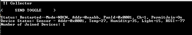
Once your sensor has joined the network, you will see sensor data printed on the terminal, as shown below
Troubleshooting
If the sensor does not join after a short while, please reset it by toggling the power switch off then on again and repeating the process for the sensor node to join the network.
- To close the network, press the collector's BTN-2 again, and its red LED will stop blinking and remain on.
Observe and Understand
- The Collector's terminal will say "Device Status: Sensor - Addr=0xX, Temp=x, RSSI=-x" when a reading is received from the sensor.
- Whenever a reading is sent from the sensor or received by the collector, the green LED will toggle on the sensor / collector respectively.
- Readings are sent from the sensor periodically. By default, the period configured by the collector is 3 seconds, but if the sensor fails to receive the configuration from the collector, it will send the readings every 3 seconds.
- Commands from the collector to the sensor can be sent only after the sensor is polling for data. These poll requests are sent by the sensor periodically, so it allows the sensor to sleep in the meantime. The default sensor poll rate is 2 seconds. This poll rate can be changed by the collector as part of the configuration message.
Note
To perform a factory reset on either device, hold down the BTN-2 button on the LaunchPad while restarting the device (power cycle or pressing the reset button). This will erase all NV memory which contains network information such as binding tables, PanID, network keys, etc.
References
TI 15.4-Stack are at https://www.ti.com/wireless-connectivity/simplelink-solutions/sub-1-ghz/overview.html
CC13xx/CC26xx Software Overview – Available at https://www.ti.com/tool/cc13xx-sw and https://www.ti.com/tool/SIMPLELINK-CC13X2-26X2-SDK.
CC13x0 Technical Reference Manual – Available here
CC13x2/CC26x2 Technical Reference Manual – Available here
This work is licensed under a Creative Commons Attribution-NonCommercial-NoDerivatives 4.0 International License.