Introduction
In this module we will learn about the Thread Border Router. What is a border router? How does the border router facilitate secure joining? How does the border router enable device to device and device to cloud communication? This tutorial will give you an overview of the workings of a border router and get you started with one based on BeagleBone Black and the SimpleLink™ Ecosystem.
In this lab we will be working with a BeagleBone Black, a WiFi router, an Android device, and a few LaunchPads to create a working Thread Network. The first three tasks will be to setup the BeagleBone Black, setup the LaunchPads, and install the necessary components onto an Android device. In the next three tasks we will look at; forming a Thread network with the border router, securely joining an example application into the Thread Network, and interacting with the example application.
This tutorial will take about three hours to complete and requires basic understanding of the Linux runtime and BeagleBoneBlack Development (see the Prerequisites section for details).
Prerequisites
BeagleBone Black Getting Started
It is highly recommended that you read and get familiar with the BeagleBone Black documentation. Specifically the getting started guide available here.
Other SimpleLink Academy Labs
You should be familiar with building and programming Thread Examples explained in the Thread CLI Project Zero.
Software
CCS version 10.3 or later with support for CC13xx/CC26xx devices installed
Serial terminal program, such as:
SD card programmer, such as:
Archival tool, such as:
- tar
- 7-Zip
Hardware
2x LaunchPads of either
1x uSD Card with minimum 8 GB storage
1x WiFi Router
1x Android Device
Recommended Reading
It is recommended to familiarize yourself with the Thread Specification.
It is recommended to read the TI-OpenThread User's Guide alongside this lab for details and further information.
Overview
In this section we give an overview of the Thread Border Router and its function within the Thread Network.
About the Thread Border Router
A Thread Border Router is a Thread Network's gateway to the outside world. A Border Router offers an off-mesh route for addressing packets. This allows a Thread Device connected to a Thread Network to communicate with an adjacent IPv6 network. In this way the Border Router facilitates device to device and device to cloud communication.
A Thread Border Router will also offer management and control functionality for a Thread Network as well as the ability to form a network. It is not necessary to start a Thread Network with a Border Router. But, since the Border Router offers a user interface and an avenue for secure Commissioning a Border Router is the natural starting place for a user.
A Thread Border Router also offers a mechanism to discover the Thread Network. The Border Router does this Through mDNS advertisements. This is the mechanism through which a Thread Commissioning Application discovers a Thread Network.
About Commissioning
Commissioning is the act of joining an untrusted device into a Thread Network by securely authenticating the device and disseminating the network information.
Attention
This section is an overview of the Commissioning process. Consult chapter 8 the Thread 1.1.1 Specification for a more in-depth explanation. Section 8.4 contains informative diagrams of the messages exchanged.
All communication on a Thread Network is secured with ENC-MIC-32. However, communication off-mesh does not benefit from the same level of security and may be transported over unsecured links. This also means that a new, untrusted, Thread device must be securely given the keys to talk with other Thread devices on the network. Thread uses DTLS with EC-JPAKE to secure connections over untrusted links when adding devices into the Thread network.
On the off-mesh side, a Commissioner discovers a Thread Network through mDNS and creates a secure connection with the Border Agent. The pass-phrase for this DTLS connection is the Border Router's administrator password, setup when the Border Router was configured. The Commissioner uses this secure tunnel to send messages to the Border Agent. The Border Agent then relays the messages onto the Thread Network. In this fashion, the Commissioner petitions the Leader to become the Active Commissioner and add its prospective joiners to the commissioning dataset.
On the Thread side, a Joiner discovers the network by sending a Discovery Request broadcast on all possible channels. If the joiner is in the Active Commissioning Dataset a router for our network will respond with a Discovery Response message, this router is called the Joiner Router. Once the Joiner has discovered the Thread Network it will begin a DTLS connection to the Active Commissioner using its PSK. This DTLS connection is proxied through the Joiner Router and Border Router if necessary. If this DTLS session is established, the Commissioner instructs the Joiner Router to securely give the Joiner the Thread Master Key.
After the commissioning process, the Joiner has been securely added to the network and can form links with other Thread devices on the network. Some important things to note; no messages were sent unencrypted, no hard coded keys were used, the Joiner's PSK was only on the Commissioner, and the network key was only sent between the Joiner Router and the Joiner with a one time link key.
About Interfaces
The Border Router is configured to bridge its available interfaces by default.
This allows for a device on the Thread Network to natively communicate with
adjacent IPv6 devices or to the cloud. By default the on-mesh prefix used by
the Border Router is fd11:22::/64. This is in the ULA
IPv6 prefix block (fc00::/7), specifically the Probabilistically Unique
prefix (fd00::/8). These addresses should not be routed on the larger
internet, and most wide area routers will refuse to forward traffic with these
addresses as a source or destination. Keep this in mind when trying to connect
with the Internet.
For this lab we will assume that you do not have an ISP that issues IPv6 addresses, or you do not wish to connect these
devices to your network just yet. We will have the BeagleBone Black issue
router advertisements on its Ethernet interface for the prefix fd11::33::/64
to allow other devices to configure ULAs routable to the Thread Network.
Task 1 – Setup the BeagleBone Black
Attention
You may be able to use newer versions of the software than is indicated in this guide. Be wary, this may introduce new functionality.
Setup Debian
Download the Debian image from the BeagleBoard website.
- For this guide the
bone-debian-9.1-lxqt-armhf-2017-08-31-4gb.img.xzimage is used, however, any newer image should work just fine.
- For this guide the
Unzip the image with tar or 7-Zip.
Write the image to your uSD Card using Etcher or Win32 Disk Imager. Consult the BeagleBoard Getting Started page for more information on updating the uSD Card image.
Connect the BeagleBone Black to your WiFi router with an Ethernet Cable. Make sure to connect the BeagleBone Black to a LAN port, not the WAN port.
Insert the programmed uSD Card into the BeagleBone Black and boot the device.
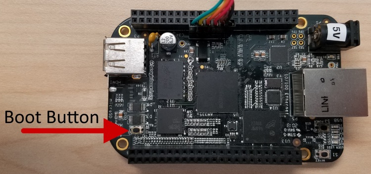
The BeagleBone Black is configured to attempt to boot from the AM335x internal storage. We want to boot from the uSD card instead. To force booting from the uSD card, hold the boot button when applying power to the BeagleBone Black.
Connect to the BeagleBone Black using SSH or through the UART port. The username for logging on is
debianwith the passwordtemppwd.The BeagleBone Black will request to have the IP address
192.168.7.2. Depending on how your router is configured, the BeagleBone Black may show up on a different IP address, the most reliable way to find the BBB's location is to log into your router and look at the DHCP table.Once you have discovered the BeagleBone Black's IP address, use PuTTY to connect to the BBB over SSH. By selecting
SSHand inputting the Host Name (or IP address) in the basic options.On connection your SSH client will prompt you to save the RSA key of the new server. PuTTY displays this as "WARNING - POTENTIAL SECURITY BREACH!". Accept the new RSA key.
Don't forget to make sure that your computer is connected to the same WiFi router as the BeagleBone Black.
The BeagleBone Black has a UART header labeled
J1. You can connect to this terminal with a USB-to-UART.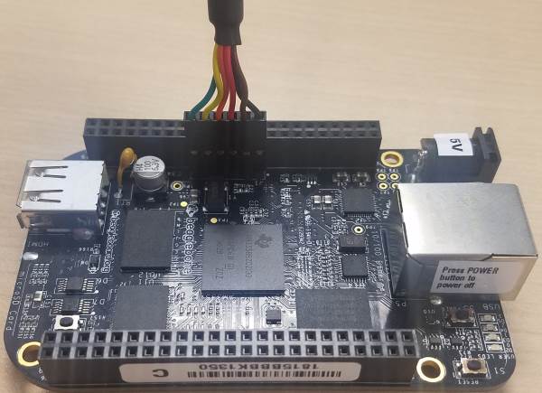
Expand the Image
The Debian image for the BeagleBone Black is most likely 3Gb large, this is not enough to build the border router source code. We will assume that you have an 8Gb or larger uSD Card for this guide. Adjust the numbers to fit your specific use-case.
We will start by deleting the partition table for the Linux file-system. Then we will create a new partition of 7Gb; we don't fill the uSD Card in-case your card isn't exactly 8Gb or you want to clone the uSD Card to another card that isn't exactly the same size. This will only change the partition table, not the contents of the partition. We then have to tell the Linux file-system to expand, filling the partition.
You will have to be logged into the BeagleBone Black for the following steps.
Some commands may need privilege escalation and may prompt you for an
administrator password. The debian user has privileges to run these
commands, you should use that user's password.
Determine the Device and Partition
Determine the current partition and start location with the command df -Th /.
debian@beaglebone:~$ df -hT /
Filesystem     Type  Size  Used Avail Use% Mounted on
/dev/mmcblk0p1 ext4  3.3G  1.6G  1.5G  52% /
/bin/sh
You will notice that the device is /dev/mmcblk0 and there is one partition
p1. If you have more than one partition, this guide might not work for you.
Use fdisk to Delete and Recreate the Partition
Start
fdiskwith the commandsudo fdisk /dev/mmcblk0.debian@beaglebone:~$ sudo fdisk /dev/mmcblk0 Welcome to fdisk (util-linux 2.29.2). Changes will remain in memory only, until you decide to write them. Be careful before using the write command. Command (m for help):/bin/sh
fdiskrequires Super User privileges to be able to edit the partition table. If you are already logged in as a Super User, such asroot, you do not need to prefixsudo.Important
fdiskwill open up an interactive shell to enter commands, the following instructions assume that you are in this shell.Print the partition table with the
pcommand.Command (m for help): p Disk /dev/mmcblk0: 7.3 GiB, 7867465728 bytes, 15366144 sectors Units: sectors of 1 * 512 = 512 bytes Sector size (logical/physical): 512 bytes / 512 bytes I/O size (minimum/optimal): 512 bytes / 512 bytes Disklabel type: dos Disk identifier: 0x0aa8d2b0 Device Boot Start End Sectors Size Id Type /dev/mmcblk0p1 * 8192 6963199 6955008 3.3G 83 Linux Command (m for help):fdisk
This shows more detailed information than the
df -hT /command did. Here we can see that the partition starts at the8192sector, this will be important later.Delete the partition with the
dcommand.Command (m for help): d Selected partition 1 Partition 1 has been deleted. Command (m for help):fdisk
Create a new partition with the
ncommand. It is important that this partition starts at the same sector we found in step 2. We will create this partition to be 7Gb large by setting the last sector as+7G. fdisk may ask to remove the ext4 signature, do not remove the signature.Command (m for help): n Partition type p primary (0 primary, 0 extended, 4 free) e extended (container for logical partitions) Select (default p): p Partition number (1-4, default 1): 1 First sector (2048-15366143, default 2048): 8192 Last sector, +sectors or +size{K,M,G,T,P} (8192-15366143, default 15366143): +7G Created a new partition 1 of type 'Linux' and of size 7 GiB. Partition #1 contains a ext4 signature. Do you want to remove the signature? [Y]es/[N]o: N Command (m for help):fdisk
(Optional) Determine the last sector of the partition with the
pcommand.Command (m for help): p Disk /dev/mmcblk0: 7.3 GiB, 7867465728 bytes, 15366144 sectors Units: sectors of 1 * 512 = 512 bytes Sector size (logical/physical): 512 bytes / 512 bytes I/O size (minimum/optimal): 512 bytes / 512 bytes Disklabel type: dos Disk identifier: 0x0aa8d2b0 Device Boot Start End Sectors Size Id Type /dev/mmcblk0p1 8192 14688255 14680064 7G 83 Linux Command (m for help):fdisk
We can see that the last sector is
14688255. The sector size is512bytes. By adding 1 for sector 0, we can determine the exact size in bytes by(14688255 + 1) * 512 = 7,520,387,072. This is useful if you want to read the uSD Card and truncate the image to exactly the right size.Write the partition table with the
wcommand.Command (m for help): w The partition table has been altered. Calling ioctl() to re-read partition table. Re-reading the partition table failed.: Device or resource busy The kernel still uses the old table. The new table will be used at the next reboot or after you run partprobe(8) or kpartx(8).fdisk
This will exit the fdisk interactive shell and return you to your main shell program. Reboot the BeagleBone Black with the command
sudo shutdown
-r now
. This may close your SSH session, wait until the BeagleBone is back up to reconnect.If you are connected to the UART debugging header, you may see the following output during the next boot:
Loading, please wait...
[    4.873285]  remoteproc1: failed to load am335x-pru0-fw
[    4.918852]  remoteproc1: request_firmware failed: -2
[    4.924046] pru-rproc 4a334000.pru0: rproc_boot failed
[    5.052414]  remoteproc1: failed to load am335x-pru1-fw
[    5.069652]  remoteproc1: request_firmware failed: -2
[    5.074889] pru-rproc 4a338000.pru1: rproc_boot failed
fsck: error 2 (No such file or directory) while executing fsck.ext4 for /dev/mmcblk0p1
fsck exited with status code 8
syslog
The BeagleBone might hang for a minute before continuing with the boot. This will be fixed in a following section.
Expand the Linux File-System
Now that we have expanded the partition in the partition table, we need to tell
the Linux file-system that it can use that extra space. For this we can use the
resize command.
debian@beaglebone:~$ sudo resize2fs /dev/mmcblk0p1
resize2fs 1.43.4 (31-Jan-2017)
Filesystem at /dev/mmcblk0p1 is mounted on /; on-line resizing required
old_desc_blocks = 1, new_desc_blocks = 1
The filesystem on /dev/mmcblk0p1 is now 1835008 (4k) blocks long.
/bin/sh
Reboot the BeagleBone Black to ensure the file-system has changed.
Fix the Initial RAM File System
The error on boot we encountered earlier can be fixed with the command
update-initramfs. This will update the initial ram file-system used on boot.
debian@beaglebone:~$ sudo update-initramfs -u
update-initramfs: Generating /boot/initrd.img-4.4.91-ti-r133
/bin/sh
Clone the border router repository
The source-code for the border router is hosted on a Git repository.
Internet Connectivity
The BeagleBone Black must be connected to the internet to clone the border router repository and download the dependent packages.
Check your connectivity by using the command wget -O /dev/null
https://github.com. The output of that command should have the phrase HTTP
request sent, awaiting response... 200 OK, if it does not you may have to
setup your proxies.
Your environment may have a proxy server setup by your network administrator. If you do, you will need to setup the BeagleBone Black with the proxy information.
Consult your network administrator for your proxy details. Then edit the
profile file /etc/profile with super user permissions and add the
following:
if true
then
    http_proxy=http://your_proxy.domain.com:80
    https_proxy=https://your_proxy.domain.com:80
    ftp_proxy=https://your_proxy.domain.com:80
    no_proxy=domain.com

    export http_proxy
    export https_proxy
    export ftp_proxy
    export no_proxy
fi
/etc/profile
The if true is to allow you to easily disable your proxy configuration if
you connect to a network that doesn't need these settings.
The BBB Setup scripts rely on the program apt for installing
dependencies. This program requires super user privileges to install. Type
sudo visudo to edit the sudo environment. This will open an editor (nano
in my case) to edit a temp file, when your changes are finished exit the
program normally.
By default all environment variables are ignored in the super user shell. To propagate the proxy information, add the following line to the sudoers environment file:
Defaults env_keep="http_proxy https_proxy ftp_proxy no_proxy"
/etc/sudoers
Then reload the environment by either; logging out and in, or by rebooting
the BBB. Finally, ensure your internet connectivity with the above wget
command.
Clone the OpenThread border router repository with git.
debian@beaglebone:~$ git clone https://github.com/openthread/ot-br-posix.git
Cloning into 'ot-br-posix'...
remote: Enumerating objects: 47, done.
remote: Counting objects: 100% (47/47), done.
remote: Compressing objects: 100% (39/39), done.
remote: Total 5267 (delta 13), reused 25 (delta 6), pack-reused 5220
Receiving objects: 100% (5267/5267), 24.60 MiB | 1.86 MiB/s, done.
Resolving deltas: 100% (2380/2380), done.
/bin/sh
Tested commit
This guide was tested with git tag
thread-br-certified-20180819 from the border router
repository.
Build the border router
These scripts will build and setup the border router on your BeagleBone Black.
The following instructions will execute the commands within a script command.
Wrapping the commands in a script call saves the output to a file, this is
helpful if you want to look at the output later on. You can remove the script
call if you don't care about the log.
The command script script.log -c 'bash ./script.sh' will save the output of
the script script.sh to the file script.log. The equivalent command without
saving the console output would be ./script.sh.
There are two sets of scripts in the border router repository;
${ot-br-posix}/bootstrap and ${ot-br-posix}/script/bootstrap. The
${ot-br-posix}/bootstrap is specific for the border router source files, the
${ot-br-posix}/script/bootstrap is platform specific setup.
Bootstrap
This bootstrap script will download and install the necessary dependencies
using apt and sets up the border router code to build.
Internet Connectivity
The BeagleBone Black must to be connected to the internet to download the border router dependencies.
Run the script/bootstrap script found in the border router repository.
debian@beaglebone:~$ cd ot-br-posix
debian@beaglebone:~/ot-br-posix$ script bootstrap.log -c 'bash ./script/bootstrap'
/bin/sh
The bootstrap step downloads all the dependencies, checks the BeagleBone Black's environment, and builds the codebase. This step will take a fair amount of time.
Setup
This setup script will build and install the border router code on the BeagleBone Black.
Run the script/setup script found in the border router repository.
debian@beaglebone:~$ cd ot-br-posix
debian@beaglebone:~/ot-br-posix$ script setup.log -c 'bash ./script/setup'
/bin/sh
The setup script builds all the necessary source files for your configuration, installs the libraries, and sets up the startup environment. This step will take some time.
Configure the border router
Now we have to configure wpantund to connect to the Network Co-Processor (NCP) LaunchPad.
LaunchPad UART
We are assuming you are going to connect a LaunchPad to the BeagleBone Black using the XDS110 USB-to-UART bridge. If you are trying to support a different configuration, this configuration will change.
Add the following lines to /etc/wpantund.conf and comment out any existing
SocketPath configurations.
Config:NCP:SocketPath "/dev/ttyACM0"
/etc/wpantund.conf
On the next boot, your BeagleBone Black will be setup to be a Border Router. Don't restart the BBB until you have setup and connected the Network Co-Processor.
Configure a Local IPv6 Network
Be a good neighbor
For this guide we are going to assume that you are trying to setup a small Local Area Network for experimentation with Thread. If you are trying to connect to a Wide Area Network, consult with the administrator of that network for proper configuration. Disconnect the BBB and WiFi router from your Internet connection
We are going to setup radvd to advertise a route to a Unique Local prefix on the BeagleBone Black's Ethernet interface. This will allow devices that support SLAAC to assign IPv6 addresses under that prefix.
It may be useful to you to enable router advertisements on the ethernet interface of your BeagleBone Black. To do this, run the standalone ipv6 script and follow the instructions printed on screen. After restarting you should disconnect the BeagleBone Black from the Wide Area Network and connect it to the Local Area Network.
debian@beaglebone:~$ cd ot-br-posix
debian@beaglebone:~/ot-br-posix$ ./script/standalone_ipv6
/bin/sh
This will install and configure radvd.
Check out the changes to /etc/radvd.conf and /etc/network/interfaces to see
what the script did. They should look something like below.
interface eth0 {
    # We want to send router adverts
    AdvSendAdvert on;

    # This is not a proper IPv6 router
    # it is only for openthread
    AdvDefaultPreference low;

    # We should advertize this prefix
    prefix fd11:33:aaaa:bbbb::/64 {
        # we want this "on link"
        AdvOnLink on;
        # devices should self-assign addresses with this prefix
        AdvAutonomous on;
        AdvRouterAddr on;
    };
};
/etc/radvd.conf
# ensure ETH0 is configured at boot
auto eth0

# Configure the IPv6 address static
# Note: IPv4 is not effected by this
iface eth0 inet6 static
    address fd11:33:aaaa:bbbb::1/64
    netmask 64
/etc/network/interfaces
This will configure the networking kernel to automatically setup the eth0
interface. These lines also tell the networking stack to statically set the
IPv6 address for that interface to fd11:33:aaaa:bbbb::1.
Task 2 – Setup the LaunchPads
This section will instruct you on how to build the NCP and Doorlock example projects, and how to flash them onto a LaunchPad. Read the READMEs that come with the examples to get more information on the specific examples.
The NCP example will be connected to to the BeagleBone Black to serve as the border router's Thread interface. The Doorlock example will be commissioned onto the Thread Network.
Import The Projects
Open CCS with an empty workspace
Open the import dialog by going to
Project→Import CCS Projects...Select
Browse...next to theSelect search-directory:dialog and navigate to theexamplesdirectory in the SDK.In
Discovered projects:selectncp_ftd_<BOARD>_tirtos_<TOOL>anddoor_lock_<BOARD>_tirtos_<TOOL>, where<BOARD>and<TOOL>are the development board and toolchain you are using.- E.g. with a CC26x2R1 LaunchPad and using the TI-CGT toolchain the
corresponding projects
ncp_ftd_CC26X2R1_LAUNCHXL_tirtos_ccsanddoor_lock_CC26X2R1_LAUNCHXL_tirtos_ccsare used.
- E.g. with a CC26x2R1 LaunchPad and using the TI-CGT toolchain the
corresponding projects
Click
Finishto import the example projects and library projects.
Build and Program the LaunchPad
First we need to setup the Network Co-Processor.
Select the NCP FTD project in the project explorer on the left.
Build the project by clicking the hammer icon on the toolbar, or by selecting to
Project→Build Project.Connect a LaunchPad to your computer with a USB cable.
Start a debugging session with the NCP project by clicking the green bug icon on the toolbar, or by selecting
Run→Debug.CCS may prompt you to update your emulator. Click the update dialog and watch the console to see if the update is successful. Close the dialog if the update is successful.
CCS may prompt you to select a debugger by the serial number if you have multiple debuggers attached. Select one and remember which LaunchPad CCS programs.
Stop the debug session by clicking the red stop icon on the toolbar.
Unplug the LaunchPad from your computer.
Plug the LaunchPad into the BeagleBone Black with the USB cable.
The NCP is now setup to work with the BeagleBone Black as a border router. We will form a Thread network with this later.
Now we need to setup a Doorlock example to demonstrate the Thread Network.
Select the doorlock project in the project explorer on the left.
Build the project by clicking the hammer icon on the toolbar, or by selecting to
Project→Build Project.Connect the second LaunchPad to your computer with a USB cable.
Start a debugging session with the doorlock project by clicking the green bug icon on the toolbar, or by selecting
Run→Debug.CCS may prompt you to update your emulator. Click the update dialog and watch the console to see if the update is successful. Close the dialog if the update is successful.
CCS may prompt you to select a debugger by the serial number if you have multiple debuggers attached. Select one and remember which LaunchPad CCS programs.
Open a terminal emulator like PuTTY, Tera Term, or use CCS with Ctrl + Shift + Alt + T and select
Serial Terminal.Discover the COM port for your LaunchPad with Device Manager.
The default settings for this UART are;
115200Baud,8Data bits, No Paraty,1Stop bit, and No Flow Control.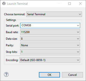
Continue the debug session by clicking the green play button on the toolbar.
You should see something like the following over the serial terminal:
TI Thread Doorlock
Press Enter for Help
<      HELP      >

Device Info: [EUI64] 0x00124b001ca76bd7  [PSKD] DRRLCK1
   Nwk Info: [Network Name] OpenThread  [ExtPanID] 0xdead00beef00cafe
   Nwk Info: [Masterkey] 0x00112233445566778899aabbccddeeff
   Nwk Info: [PAN ID] 0xffff  [Channel] 14  [Short Addr] 0xfffe
  Role Info: [Device Role] Disabled
  Conn Info: [Status] Disabled
   APP Info: [Doorlock State] unlock
doorlock terminal
If you have an LCD screen connected to your LaunchPad, you will see something like the following on-screen:
pskd:
DRRLCK1
EUI64:
0x00124b0013149681
doorlock display
This information will be useful when commissioning the doorlock into the
Thread network later. The commissioning application will need to know the
EUI64 of the joining device and its PSK.
This can either be entered manually or by embedding the information in a QR
code. This QR code can be created with any QR code generator, for example
this one. The string for the QR code is v=1&&eui=<EUI64>&&cc=<PSKD>
where <EUI64> is the joiner's EUI64 and <PSKD> is the joiner's pre-shared
key. The EUI64 must have capital letters and not have the 0x prefix. The
string for the above Doorlock example would be
v=1&&eui=00124B0013149681&&cc=DRRLCK1.
Task 3 – Setup Off-mesh Devices
The Thread Group has created an Android application for commissioning devices onto a Thread Network. This application discovers Thread Border Routers through mDNS and acts as an off-mesh Commissioner for those networks.
You can download the Thread 1.1 Commissioning application. The source code for this application is available to Thread Group Members by request.
The example applications in the SDK use CoAP to expose endpoints. A CoAP client is required to connect with the CoAP servers hosted on the embedded devices. Spitfirefox is a simple CoAP client for Android devices. Copper is a CoAP client built as a plug-in for the Firefox browser.
Firefox compatibility
Firefox 56+ removed some features that were necessary for the copper plug- in to function. If you wish to use the copper plug-in, it is required to install an old version of Firefox.
Task 4 – Start the Border Router
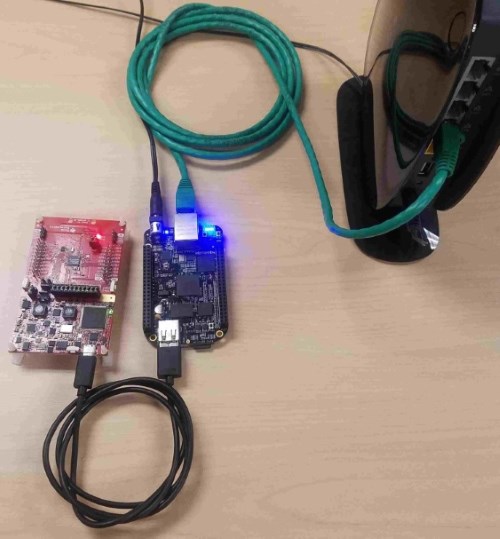
Make sure that the BeagleBone Black and the LaunchPad you programmed with the Network Co-Processor firmware are connected like the image below:
Restart your BeagleBone Black to make sure that all configurations have taken effect.
The BeagleBone Black will host a web server that can be used to manage the
border router. Log into the BeagleBone Black and use the command ifconfig to
discover the IPv4 address of the eth0 interface. You could also log into your
router to find the DHCP address table.
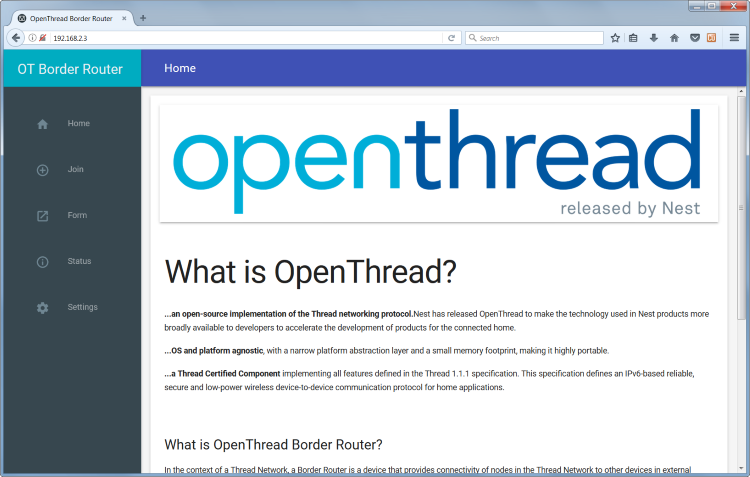
Navigate to the address of the BeagleBone Black with a web browser. The
BeagleBone Black in my network is at address 192.168.2.3. You should see the
following home screen:
Click on the Form button in the tray on the left.
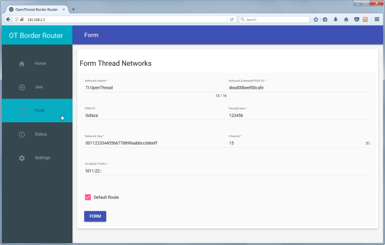
Set the parameters of your new network. The defaults are fine to start a
network. Remember the value that is in Passphrase, this will be important
with the commissioning application.
Click the FORM button at the bottom of the page to start forming a Thread
network.
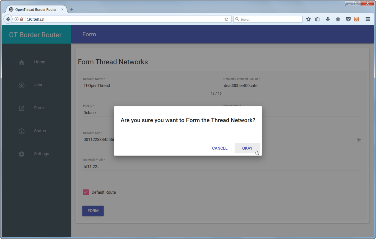
Your Thread Network is now setup with the Network Co-Processor as the Leader. If you have a sniffer running, you should see the network being formed.
Task 5 – Commission the Doorlock Example
Plug in the LaunchPad you programmed with the Doorlock example earlier.
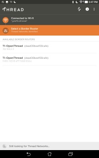
Connect your Android Device to the network and open up the Thread 1.1 Commissioning App. You should see the following screen.
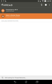
If the Border Router's mDNS service is in scope of the mobile device the IPv4 and IPv6 addresses should appear.
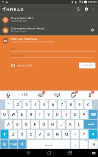
Select one of the addresses from the list. You will be asked to enter the Administrator Password, this is the Passphrase you entered when you formed the network earlier.
The Thread Commissioning app may ask for permission to use the camera. You can either grant the permissions to the app, or you can enter the EUI and PSK manually. This information should have been obtained at the end of the Task 4.
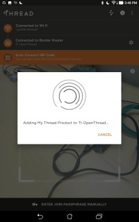
Once a dialog appears with the phrase "Adding My Thread Product to
TI-ThreadDemo", the Commissioner is ready to join the Doorlock into the Thread
Network. Click the right button (BTN-2) on the LaunchPad to start the joining
process. The phrase Joining NWK... should appear on the LCD screen or on the
UART serial port.
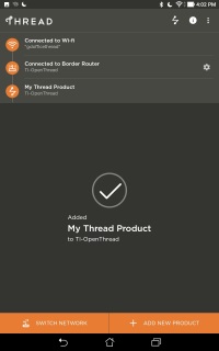
After a few moments the Doorlock should be allowed to join the Thread Network. You will see the lock icon appear on the LCD screen or the state change being logged out the UART serial port. You should also see the Thread Commissioning App notify that the device has joined the Thread Network.
Task 6 – Interact with the Doorlock example
Connect to the network the border router is connected to. Your computer should
have an address under the fd11:33::/64 prefix or something similar, as
specified in radvd.conf.
Check the connection with pings
If you were to type the command ifconfig in a terminal, you should get
something like the following:
$ ifconfig eth0
eth0: flags=4163<UP,BROADCAST,RUNNING,MULTICAST>  mtu 1500
        inet 192.168.2.4  netmask 255.255.255.0  broadcast 192.168.2.255
        inet6 fe80::d41a:e707:2ade:469c  prefixlen 13  scopeid 0x20<link>
        inet6 fd11:33::d41a:e707:2ade:469c  prefixlen 64  scopeid 0x0<global>
Or on Windows use the command ipconfig:
>ipconfig

Windows IP Configuration


Wireless LAN adapter Wireless Network Connection:

   IPv6 Address. . . . . . . . . . . : fd11:33::d41a:e707:2ade:469c
   Temporary IPv6 Address. . . . . . : fd11:33::ec0a:8ed:91cd:ab6f
   Link-local IPv6 Address . . . . . : fe80::d41a:e707:2ade:469c%13
   IPv4 Address. . . . . . . . . . . : 192.168.2.4
   Subnet Mask . . . . . . . . . . . : 255.255.255.0
   Default Gateway . . . . . . . . . : fe80::6ac9:bff:feee:635e%13
                                       192.168.2.1
You can use the command ping6 to ensure that you are connected to the
example.
$ ping6 -c 4 fd11:22::1
PING fd11:22::1(fd11:22::1) 56 data bytes
64 bytes from fd11:22::1: icmp_seq=1 ttl=64 time=39.8 ms
64 bytes from fd11:22::1: icmp_seq=2 ttl=64 time=34.5 ms
64 bytes from fd11:22::1: icmp_seq=3 ttl=64 time=34.9 ms
64 bytes from fd11:22::1: icmp_seq=4 ttl=64 time=35.1 ms

--- fd11:22::1 ping statistics ---
4 packets transmitted, 4 received, 0% packet loss, time 3004ms
rtt min/avg/max/mdev = 34.594/36.147/39.883/2.171 ms
Or the command ping on Windows.
>ping fd11:22::1

Pinging fd11:22::1 with 32 bytes of data:
Reply from fd11:22::1: time=33ms
Reply from fd11:22::1: time=32ms
Reply from fd11:22::1: time=30ms
Reply from fd11:22::1: time=31ms

Ping statistics for fd11:22::1:
    Packets: Sent = 4, Received = 4, Lost = 0 (0% loss),
Approximate round trip times in milli-seconds:
    Minimum = 30ms, Maximum = 33ms, Average = 31ms
Change the lock's state with Copper
On your device, open Firefox and navigate to the URL
coap://[fd11:22::1]:5683/doorlock/lockstate. This will open up a page to use
the Copper CoAP client.
Try to get the current state of the lock by clicking the GET button at the
top. You should see either lock or unlock depending on the current state.
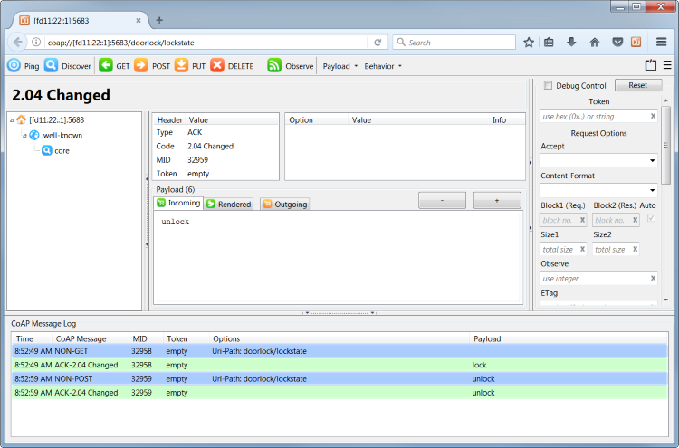
Now click on the Outgoing tab in the center and enter the opposite state that
the lock is in right now. If it is locked, enter unlock; if it is unlocked,
enter lock. When you click POST at the top, the image on the embedded
device's screen should change. If you don't have an LCD screen hooked up, you
can see the state change with the UART serial port.
You now have communication from a Thread device to an Ethernet or WiFi device.
Further Reading
It is recommended that you read the Developing Thread Applications chapter of the TI-OpenThread User's Guide for more information on the software development environment.
Familiarize yourself with the TI-OpenThread APIs and OpenThread APIs.
Consider looking at the RFCs that define UDP (RFC 768) and CoAP (RFC 7959).
This work is licensed under a Creative Commons Attribution-NonCommercial-NoDerivatives 4.0 International License.