Note
As of 2021, this document follows the Appropriate Language nomenclature directive from Bluetooth SIG. The SDK project names, APIs and code are not yet ported and use the old nomenclature. For details on how to correlate between the two, please open the PDF document Appropriate Language Mapping Tables.
Introduction
This module is an advanced study of the Over the Air Download (OAD) feature of the TI BLE5-Stack. The estimated time to complete this lab is between 1-2.5 hours. It is assumed that the reader has a basic knowledge of embedded C tool chains and general C programming concepts. This lab is intended as additional material for users who are already familiar with the OAD concepts presented in the OAD Chapter of the BLE5-Stack User's Guide.
OAD refers to the ability for an image to download a new executable image, over the air using the BLE5 protocol stack. A number of software components are involved in this process and TI uses OAD to refer to all of them as a software system.
First, the lab will cover an overview of a typical BLE5-Stack image and examine
the high level anatomy of an OAD image. The next task will be running the out of
the box demo for OAD using BTool, highlighting critical concepts along the way.
After the user is comfortable with performing an OAD, the lab will cover adding
OAD to an existing project, using multi_role as an example. The lab will
conclude with a study of OAD debugging techniques and explain how to avoid
common OAD pitfalls. As a bonus, the lab will review how to create an OAD
production image.
Prerequisites
Hardware
For this lab, you need two Bluetooth-enabled development boards. Supported devices are:
- SimpleLink™ CC26x2R LaunchPad™
- SimpleLink™ CC1352R LaunchPad™
- SimpleLink™ CC1352P LaunchPad™
- SimpleLink™ CC2652RB LaunchPad™
Software for desktop development
- CCS 11.0 or IAR 8.50.9 installed with support for CC13xx/CC26xx devices
- SimpleLink™ CC13XX and CC26XX 5.30 SDK
- BTool (located in the
\tools\ble5stackdirectory of the SimpleLink™ Device SDK) - SRecord
- UNIFLASH
These devices are interchangeable in the lab.
Recommended reading
- SimpleLink Academy: Bluetooth Low Energy Fundamentals
- SimpleLink Academy: Making a Custom Profile
OAD Documentation
It is recommended to review the OAD Chapter of the BLE5-Stack User's Guide before starting this lab.
Getting started – Desktop
Install the Software
Run the SimpleLink SDK installer. This gives you the SDK with TI-RTOS included at the default location
C:\ti\simplelink_cc13xx_cc26xx_sdk_x_xx_xx_xx.
Additionally, for flashing hex files UNIFLASH will be needed
Modify/Load the Software
Load Board #1
Load the first board with the host_test sample application that will enable communication with BTool.
The host_test project is found in the ble5stack examples folder:
<SDK_INSTALL_DIR>\examples\rtos\CCxxxx_LAUNCHXL\ble5stack\host_test\tirtos
Load Board #2
Load the second board with simple_peripheral_oad_offchip project that supports OAD. The simple_peripheral_oad_offchip project is found in the ble5stack examples folder:
<SDK_INSTALL_DIR>\examples\rtos\CCxxxx_LAUNCHXL\ble5stack\simple_peripheral_oad_offchip\tirtos
Additionally, later in the lab we will use the following projects:
multi_role: <SDK_INSTALL_DIR>\examples\rtos\CCxxxx_LAUNCHXL\ble5stack\multi_role\tirtos
project_zero: <SDK_INSTALL_DIR>\examples\rtos\CCxxxx_LAUNCHXL\ble5stack\project_zero\tirtos
As detailed in the introduction, the following tasks will cover some of the primary topics related to OAD using the BLE5-Stack.
Anatomy of an OAD
This section seeks to explain the various components involved in an OAD image from a high level. Each software component will be treated as a building block that is added to a vanilla BLE5-Stack image to eventually build an OAD image.
Default Non OAD Image
We will begin with the template for a standard BLE5-stack image that does not have OAD enabled.
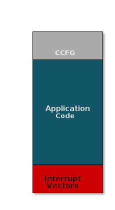
There are three main components of this image:
- The instructions/constants that implement the compiled form of the program (application code)
- The reset vectors in the ARM Cortex M format: ARM Cortex M4F Vector Table
- The CCFG, which contains chip configuration parameters, see the Technical Reference Manual
These three components are required for any image that is to run on the CC26x2R or CC13x2R. The goal of OAD is to get an executable image of this form on the device via an over the air update, no JTAG or wires required.
However, in order to achieve the goal of making the image pictured above upgradeable over the air, a few software components must be set in place.
Image Fragmentation/ Image Header
Even with the largest payload size supported by the Bluetooth Low Energy Specification, an entire CC26x2/CC13x2 image cannot be sent in an single packet. Therefore, the image to be sent over the air must be fragmented into a size that will fit into BLE GATT payloads.
The figure below pictures fragmentation of the stock image into GATT payloads.
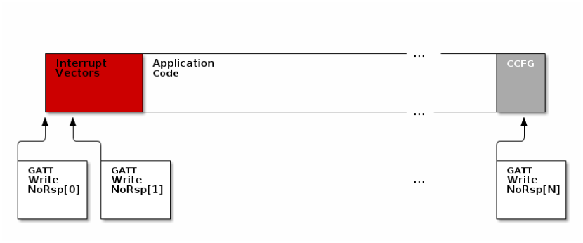
As seen in the figure above, it will take many GATT packets to send a complete image over the air using the BLE protocol. Each of these packets containing OAD image information is referred to as an OAD Block.
However, there is no way for the receiving device to know information about the incoming image. This problem is solved by using the OAD Image Header. The OAD Image Header contains metadata describing the image and is used by the application and BIM to determine the suitability of an image for downloading or loading. Other benefits of the OAD Image Header are:
- Image metadata is bundled as part of the image
- A running image can query knowledge about itself by reading the header
- Bootloader software can read the header to determine which image(s) are present and active
- Information about the incoming image is available to the target early in the OAD process.
Now, that we are sold on the benefits of an image header in an OAD system, here is an updated drawing of the stock image with an image header added.
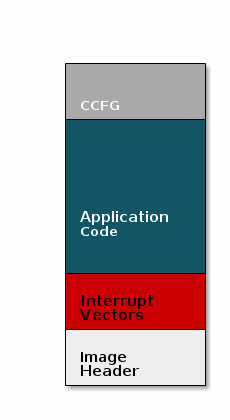
Comparison: Image with and without header
The space available to the code section of the image is shrunk to accommodate
the header, and the reset vectors are pushed back to accommodate the header.
These changes are specified in the linker script (shrinking app space) and the
RTOS .cfg file (relocating reset vectors).
Quiz
Why is an image header needed for OAD? (Select all that apply)
Boot Image Manager (BIM)
A running image cannot update itself. This means that incoming OAD image must be stored in a temporary location while it is being received. This temporarily location can be a reserved location in internal flash outside of the executable area covered in the first image. Alternatively, the temporary location can be in an external flash chip
After the download is complete, some code must determine if the new image is valid, and if current image should be overwritten, and finally execute the new image.
This piece of code is referred to the Boot Image Manger (BIM) in the TI OAD solution.
BIM is intended to permanently remain on the device, meaning it persists through many OADs and cannot be updated.
BIM will run every time the device boots and determine if a new image should be loaded and run (based on image header).
Furthermore, the BIM and CCFG structure are tied together, because both are required for a successful device boot.
The CCFG is needed by the boot ROM and startup firmware for device trim and to
determine where program execution is to start from. By default the boot ROM will
jump to address 0x00000000 and look for a vector table, but this region is
now occupied by the image header. A custom CCFG must be used to instruct the
device to jump directly to the BIM.
From there the BIM will perform device trim based on the CCFG settings, and determine and load the optimal image based on the OAD image header.
The BIM code will require more reserved space in our system. See below for the memory map after a BIM has been added to the last image.
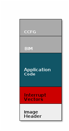
CCFG and BIM
The BIM is responsible for linking and defining the CCFG structure, instead of the application as in the non OAD case. This ensures that the device always will always execute the BIM after boot.
Quiz
Should the file ccfg_app_ble.c be included and linked as part of the
application?
OAD Protocol/ BLE Profile
Currently we have covered all the necessary building blocks for updating an image local to the target device. The only missing piece is a vehicle for sending the OAD blocks over the air, and storing them on the target device.
This functionality is implemented by the BLE5-Stack OAD profile. As covered in the Custom Profile lab, the GATT profile is the vehicle for sending data over BLE.
At a high level, the BLE5-Stack OAD profile is responsible for receiving the following
- Determining if the candidate image should be accepted for download
- Receiving and unpacking image blocks and storing them
- Writing the received blocks to non volatile storage
- Verifying the received image post download
The BLE5-Stack OAD profile is implemented in the oad.c file and its associated
flash wrappers. Later, the module will cover the steps required to add the
BLE5-Stack OAD profile to a project.
Quiz
Does the image updated via OAD need to contain OAD related services in order for subsequent OADs to work?
Task 1 – Running the OAD Demo
The BLE5-Stack User's Guide has two sections dedicated to performing an BLE OAD using BTool.
First, you will need to setup the OAD environment by flashing the devices with their required images and initializing them properly. These steps are covered by the Setting up the BLE OAD Environment Chapter. Follow the steps in the guide to prepare for an OAD. Use the
simple_peripheral_oad_offchipDebugconfiguration as the sample application.Debug
Don't forget to use the
Debugbuild configuration. If you do not use this config then certain menu options will not be available to you later in this lab. In addition, you must enable the OAD_DEBUG define by checking the box inside: Sysconfig → BLE → Advanced Settings → OAD Only Defins → OAD Debug.
Quiz
In the OAD ecosystem, BTool and host_test image combined together fulfill
which role?
Using the two button menu feature on
simple_peripheral_oad_offchipkey in the following sequence OAD Debug → Create Factory Image. This will overwrite the current factory image in external flash. Wait until the message Successfully created factory image appears.Update factory image
In order to view the menu you will need to open the COM port on this device. For information on how to open the COM port, see the "Connect a terminal program" section of the BLE Fundamentals Lab
Do not unplug or reset the device during factory image update. This should take around 30s to complete, wait until the success message is displayed.
Now that the OAD ecosystem is ready for use, switch over to project_zero.
- Re-build the
project_zeroproject, but do not flash it on the device. Instead, follow the steps detailed in the BLE5-Stack User's Guide chapter titled Performing a BLE OAD. At this point you will have updated yoursimple_peripheral_oad_offchiptoproject_zerousing OAD.
Quiz
Select all of the following that are true about OAD Target devices.
Task 2 – Revert to Factory Image
We have now updated to a completely new application via OAD. In an actual software development cycle, it is possible that this new application may contain a bug. When designing an OAD solution, it is always important to allow a downloaded application to be reverted to a known working configuration.
TI has created a factory image check procedure to be performed in the
main() of the application project. The code is simple and will check the state
of a given PIN at boot, and if the PIN is asserted, it will corrupt the CRC
value of the running application and reboot.
After reboot the BIM will revert back to the factory image.
The check shall occur before any of the stacks boot or other user threads have been created. The sample applications in the SDK have aligned on using the left button on the LaunchPad to check for factory image.
For the TI OAD profile this recovery mechanism is called the factory image. In this task we will revert back to the factory image created in task 1.
Press both the reset button and the left button at the same time.
Release the reset button while leaving the left button pressed.
Continue to hold the left button,
project_zerowill display the following:

At this point the device should have booted back into the original
simple_peripheral_oad_offchip image.
Task 3 – Add OAD to Multi Role
This section will detail how to add BLE OAD to an existing project. The intention is to start with an unmodified sample app from the SDK that does not currently use OAD, and add OAD to it.
Customers can use this section to add OAD to their existing projects. The example project used to demonstrate these steps will be multi_role.
Project Changes
In order to add OAD, certain files and include paths should be added to the project, these are detailed in the list below.
Change the linker file.
- Remove or exclude the
cc13x2_cc26x2_app.cmdfile from the project and addcc13x2_cc26x2_app.cmdfrom the simple peripheral oad offchip project instead.
- Remove or exclude the
Add the following to the linker defines:
OAD_IMG_E=1: Tell the linker that off-chip OAD is to be usedSECURITY=1: Enable security if desired (optional)
(optional) Add the following define to the compiler predefined symbols (Project → Properties → BUILD → ARM Compiler → Predefined Symbols)
SECURITY: Enable security if desired
In SysConfig, make the following configurations:
- In BLE config → General Configuration, set Maximum size of PDU (bytes) to 251.
Changing PDU Size
This define will control the negotiated block size. Block Size is derived from MTU size, which is derived by the minimum of the local supported PDU size and peer's supported MTU. Refer to the notes about OAD Block size in the BLE5-Stack User's Guide (Over the Air Download (OAD) → BLE-Stack OAD Profile → OAD Block Size Rules)
- In Advanced Settings → OAD Only Defines, check for Led Debug and OAD Feature.
- In TI Devices → Device Configuration, uncheck the Enable Bootloader box.
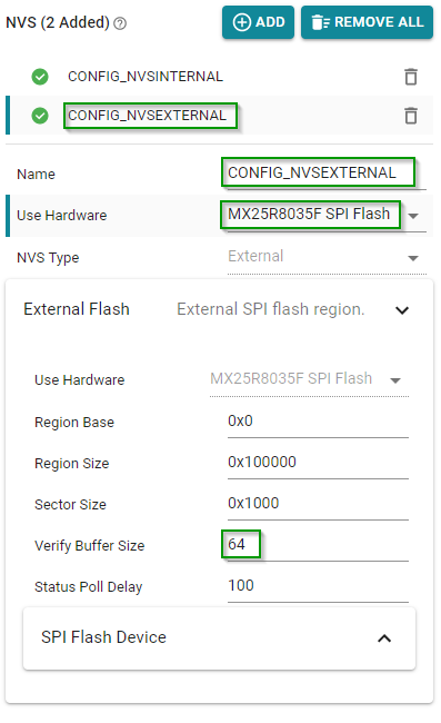
- In TI DRIVERS config, add an NVS instance by pressing the plus sign next to NVS. Configure it as follows:
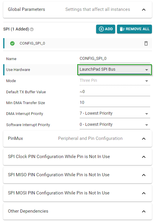
- Configure an SPI instance. (SPI is used for communication with the external flash.) If you are using a LaunchPad, you can choose the LaunchPad SPI Bus hardware and not need to make any other changes. If you are using a custom board, configure accordingly.
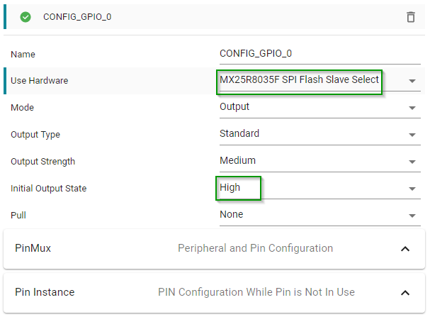
- Add a GPIO for the SPI Slave Select. Configure as follows:
Relocate the TI-RTOS reset vectors in the application's
.cfgfile. Replacem3Hwi.resetVectorAddress = 0x0;with:/* Put reset vector after OAD metadata */ var compilerOpts = prog.build.target.ccOpts.prefix; // Get the target compiler options var regex = /(?:\-\-define\=)(\w*)(?:\=*\w*\s)/g; var compilerDefs = []; while ((tmp = regex.exec(compilerOpts)) !== null) compilerDefs.push(tmp[1]); // Parse compiler symbols if (compilerDefs.indexOf('SECURITY') > -1) { // Check for SECURITY compiler symbol m3Hwi.resetVectorAddress = 0x90; // Image B Reset Vector Address } else { m3Hwi.resetVectorAddress = 0x50; // Image A Reset Vector Address }Add the following files to the project. These files can be found in the following locations:
<SimpleLink SDK> → source → ti → ble5stack → profiles → oad → cc26xx
<SimpleLink SDK> → source → ti → common → cc26xx → crc
<SimpleLink SDK> → source → ti → common → cc26xx → flash_interface
<SimpleLink SDK> → source → ti → common → cc26xx → flash_interface → external
<SimpleLink SDK> → source → ti → common → cc26xx → oad
<SimpleLink SDK> → source → ti → common → cc26xx → bimoad.c: OAD profile implementationoad.h: Public OAD profile API definitioncrc32.c: CRC32 algorithm and helper functionscrc32.h: CRC32 public API definitionflash_interface.h: A flash abstraction layer that abstracts flash operations for on and off-chip OAD.flash_interface_ext_rtos_NVS.c: TI-RTOS NVS driver implementation of flash interface for off-chip OAD.oad_image_header.h: Structure definitions for the OAD image headeroad_image_header_app.c: Application definition of image header.oad_defines.h: Common header containing OAD definitionsoad_util.c: Implementation of OAD utility functionsoad_util.h: Public API definition of OAD utility functionsbim_util.h: Public API definition of utility functions shared between the BIM and application.bim_util.c: Implementation of BIM utility functions
The following files are only required if the optional revert to factory image feature is required:
mark_switch_factory_img.h: Public API definition for factory image switch.mark_switch_factory_img.c: Implementation of factory image switching mechanism.
The following pre-processor include paths should be added to the project.
${COM_TI_SIMPLELINK_CC13XX_CC26XX_SDK_INSTALL_DIR}/source/ti${COM_TI_SIMPLELINK_CC13XX_CC26XX_SDK_INSTALL_DIR}/source/ti/ble5stack
Add the OAD image tool post build step to the project. Be sure to not delete the existing hex file step. Place the OAD step after it!
The following should be used with secure OAD (i.e.
SECURITYdefined);${COM_TI_SIMPLELINK_CC13XX_CC26XX_SDK_INSTALL_DIR}/tools/common/oad/oad_image_tool --verbose ccs ${PROJECT_LOC} 7 -hex1 ${ConfigName}/${ProjName}.hex -k ${COM_TI_SIMPLELINK_CC13XX_CC26XX_SDK_INSTALL_DIR}/tools/common/oad/private.pem -o ${ConfigName}/${ProjName}_oadThe following should be used with unsecure OAD (i.e. no
SECURITYdefined):;${COM_TI_SIMPLELINK_CC13XX_CC26XX_SDK_INSTALL_DIR}/tools/common/oad/oad_image_tool --verbose ccs ${PROJECT_LOC} 7 -hex1 ${ConfigName}/${ProjName}.hex -o ${ConfigName}/${ProjName}_oad
Post build steps
Some applications in the SDK will generate output files that are formatted as ${ProjName}_${ConfigName}.hex while others are ${ProjName}.hex. Check to be sure that your ouput hex file format matches the one in the OAD post build step above.
Remove or exclude the
cc13x2_cc26x2_app_and_stack_agama.icffile from the project and addcc26xx_app_and_stack_agama.icffrom the simple peripheral oad offchip project instead. Change also the linker file in the project options.$SIMPLELINK_CC13XX_CC26XX_SDK_INSTALL_DIR$/examples/rtos/CC26X2R1_LAUNCHXL/ble5stack/simple_peripheral_oad_offchip/tirtos/iar/cc26xx_app_and_stack_agama.icf(optional) Add the following define to the compiler predefined symbols
-DSECURITY: Enable security if desired (optional)
In SysConfig, make the following configurations:
- In BLE config → General Configuration, set Maximum size of PDU (bytes) to 251.
Changing PDU Size
This define will control the negotiated block size. Block Size is derived from MTU size, which is derived by the minimum of the local supported PDU size and peer's supported MTU. Refer to the notes about OAD Block size in the BLE5-Stack User's Guide (Over the Air Download (OAD) → BLE-Stack OAD Profile → OAD Block Size Rules)
- In Advanced Settings → OAD Only Defines, check for Led Debug and OAD Feature.
- In TI Devices → Device Configuration, uncheck the Enable Bootloader box.
- In TI DRIVERS config, add an NVS instance by pressing the plus sign next to NVS. Configure it as follows:
- Configure an SPI instance. (SPI is used for communication with the external flash.) If you are using a LaunchPad, you can choose the LaunchPad SPI Bus hardware and not need to make any other changes. If you are using a custom board, configure accordingly.
- Add a GPIO for the SPI Slave Select. Configure as follows:
Relocate the TI-RTOS reset vectors in the application's
.cfgfile. Each application has two of these (debug, release), apply change for both. Replacem3Hwi.resetVectorAddress = 0x0;with:/* Put reset vector after OAD metadata */ var compilerOpts = prog.build.target.ccOpts.prefix; // Get the target compiler options var regex = /(?:\-\-define\=)(\w*)(?:\=*\w*\s)/g; var compilerDefs = []; while ((tmp = regex.exec(compilerOpts)) !== null) compilerDefs.push(tmp[1]); // Parse compiler symbols if (compilerDefs.indexOf('SECURITY') > -1) { // Check for SECURITY compiler symbol m3Hwi.resetVectorAddress = 0x90; // Image B Reset Vector Address } else { m3Hwi.resetVectorAddress = 0x50; // Image A Reset Vector Address }The following files should be removed from the project:
ccfg_app_ble.c(in Startup folder) : The BIM links the CCFG in an OAD system.
Add the following files to the project. These files can be found in the following locations:
<SimpleLink SDK> → source → ti → ble5stack → profiles → oad → cc26xx
<SimpleLink SDK> → source → ti → common → cc26xx → crc
<SimpleLink SDK> → source → ti → common → cc26xx → flash_interface
<SimpleLink SDK> → source → ti → common → cc26xx → oad
<SimpleLink SDK> → source → ti → common → cc26xx → bimoad.c: OAD profile implementationoad.h: Public OAD profile API definitioncrc32.c: CRC32 algorithm and helper functionscrc32.h: CRC32 public API definitionflash_interface.h: A flash abstraction layer that abstracts flash operations for on and off-chip OAD.oad_image_header.h: Structure definitions for the OAD image headeroad_image_header_app.c: Application definition of image header.oad_defines.h: Common header containing OAD definitionsoad_util.c: Implementation of OAD utility functionsoad_util.h: Public API definition of OAD utility functionsbim_util.h: Public API definition of utility functions shared between the BIM and application.bim_util.c: Implementation of BIM utility functionsflash_interface_ext_rtos_NVS.c: TI-RTOS NVS driver implementation of flash interface for off-chip OAD.
The following files are only required if the optional revert to factory image feature is required:
mark_switch_factory_img.h: Public API definition for factory image switch.mark_switch_factory_img.c: Implementation of factory image switching mechanism.
The following pre-processor include paths should be added to the project.
$SIMPLELINK_CORE_SDK_INSTALL_DIR$\source\ti$SRC_BLE_DIR$
Modify the post build step to support OAD on the project. On IAR, a batch script is used to execute multiple post build commands.
Ensure the following post-build command line is entered in IAR:
$SIMPLELINK_CC13XX_CC26XX_SDK_INSTALL_DIR$/tools/ble5stack/oad/oad_postbuild.bat $TARGET_BPATH$ $PROJ_DIR$ $CONFIG_NAME$ $PROJ_FNAME$ $SIMPLELINK_CC13XX_CC26XX_SDK_INSTALL_DIR$ $EXE_DIR$ $TARGET_BNAME$With the above post-build command entered, navigate to the oad_postbuild.bat file and open it with a text editor.
Note
Example projects in the SDK supporting OAD have SECURITY defined by default. As such, the above oad_postbuild.bat script should only be used for secure OAD.
If an unsecure OAD is desired, the oad_postbuild.bat script needs to be modified. The instructions below should only be followed for unsecure OAD.
Warning
Do not modify the oad_postbuild.bat script directly. This will likely break the functionality of the out-of-box, default example OAD projects in the SDK . Copy the oad_postbuild.bat script and rename it to oad_postbuild_unsecure.bat. When doing this, don't forget to modify the post-build command line mentioned above to point to the new unsecure version you just created.
After you've followed the above instructions for unsecure OAD, proceed by modifying the oad_postbuild_unsecure.bat file. Be sure to only modify the second command in the file.
The following should be used with unsecure OAD (i.e. no
SECURITYdefined):%5/tools/common/oad/oad_image_tool.exe --verbose iar %2 7 -hex1 %3/Exe/%4.hex -o %6/%7_oad
Post build steps
Some applications in the SDK will generate output files that are formatted as ${ProjName}_${ConfigName}.hex while others are ${ProjName}.hex. Check to be sure that your output hex file format matches the one in the OAD post build step above.
Code Changes
The following changes need to be performed in the source code of the application
Performing the following changes in the high level application task file.
Add the required include directives in
multi_role.cnear the other include directives:#include <profiles/oad/cc26xx/oad.h> #include <ti/common/cc26xx/oad/oad_image_header.h> #include <ti/devices/DeviceFamily.h> #include DeviceFamily_constructPath(driverlib/sys_ctrl.h)Add the OAD events to the app's
*_ALL_EVENTSmacro (be sure to add line breaks as necessary) inmulti_role.c:OAD_QUEUE_EVT | \ OAD_DL_COMPLETE_EVT)After the above step the
MR_ALL_EVENTSshould look like this#define MR_ALL_EVENTS (MR_ICALL_EVT | \ MR_QUEUE_EVT | \ OAD_QUEUE_EVT | \ OAD_DL_COMPLETE_EVT)Add the following declarations under the LOCAL VARIABLES section in
multi_role.c:static uint8_t numPendingMsgs = 0; static bool oadWaitReboot = false;Add the following forward declarations under the LOCAL FUNCTIONS section in
multi_role.cstatic void multi_role_processOadWriteCB(uint8_t event, uint16_t arg); static void multi_role_processL2CAPMsg(l2capSignalEvent_t *pMsg); static void multi_role_processConnEvt(Gap_ConnEventRpt_t *pReport);Add the following callback initializers under the PROFILE CALLBACKS section in
multi_role.cstatic oadTargetCBs_t multi_role_oadCBs = { .pfnOadWrite = multi_role_processOadWriteCB // Write Callback. };Inside the
multi_role.c::multi_role_init(), add the following:// Open the OAD module and add the OAD service to the application if(OAD_SUCCESS != OAD_open(OAD_DEFAULT_INACTIVITY_TIME)) { /* * OAD cannot be opened, steps must be taken in the application to * handle this gracefully, this can mean an error, assert, * or print statement. */ } else { // Register the OAD callback with the application OAD_register(&multi_role_oadCBs); }Add the OAD event processing in
multi_role.c::multi_role_taskFxn()do this after ICall event processing:// OAD events if(events & OAD_QUEUE_EVT) { // Process the OAD Message Queue uint8_t status = OAD_processQueue(); // If the OAD state machine encountered an error, print it // Return codes can be found in oad_constants.h if(status == OAD_DL_COMPLETE) { // Report status } else if(status == OAD_IMG_ID_TIMEOUT) { // This may be an attack, terminate the link GAP_TerminateLinkReq(OAD_getactiveCxnHandle(), HCI_DISCONNECT_REMOTE_USER_TERM); } else if(status != OAD_SUCCESS) { // Report Error } } if(events & OAD_DL_COMPLETE_EVT) { // Register for L2CAP Flow Control Events L2CAP_RegisterFlowCtrlTask(selfEntity); }Process L2CAP messages from the stack. This will replace the existing
L2CAP_SIGNAL_EVENTcase statement inside ofmulti_role.c::multi_role_processStackMsg().case L2CAP_SIGNAL_EVENT: { // Process L2CAP free buffer notification multi_role_processL2CAPMsg((l2capSignalEvent_t *)pMsg); break; }Make an application level L2CAP handler function as below. Add this function at the end of
multi_role.cstatic void multi_role_processL2CAPMsg(l2capSignalEvent_t *pMsg) { static bool firstRun = TRUE; switch (pMsg->opcode) { case L2CAP_NUM_CTRL_DATA_PKT_EVT: { /* * We cannot reboot the device immediately after receiving * the enable command, we must allow the stack enough time * to process and respond to the OAD_EXT_CTRL_ENABLE_IMG * command. This command will determine the number of * packets currently queued up by the LE controller. */ if (firstRun) { firstRun = false; // We only want to set the numPendingMsgs once numPendingMsgs = MAX_NUM_PDU - pMsg->cmd.numCtrlDataPktEvt.numDataPkt; // Wait until all PDU have been sent on cxn events Gap_RegisterConnEventCb(multi_role_processConnEvt, GAP_CB_REGISTER, OAD_getactiveCxnHandle()); /* Set the flag so that the connection event callback will * be processed in the context of a pending OAD reboot */ oadWaitReboot = true; } break; } default: break; } }Add a connection event processing function, do this at the bottom of
multi_role.cstatic void multi_role_processConnEvt(Gap_ConnEventRpt_t *pReport) { /* If we are waiting for an OAD Reboot, process connection events to ensure * that we are not waiting to send data before restarting */ if(oadWaitReboot) { // Wait until all pending messages are sent if(numPendingMsgs == 0) { // Reset the system SysCtrlSystemReset(); } else { numPendingMsgs--; } } else { // Process connection events normally } }Add an event handler function to process OAD events, do this at the bottom of
multi_role.cstatic void multi_role_processOadWriteCB(uint8_t event, uint16_t arg) { Event_post(syncEvent, event); }Add the following code to the
ATT_MTU_UPDATED_EVENThandler. This should be processed by the application when it receives a messages ofgattMsgEvent_tfrom the stack. You can find this inmulti_role.c::multi_role_processGATTMsg()OAD_setBlockSize(pMsg->msg.mtuEvt.MTU);
Reset OAD if connection drops
Add the following code to the
GAP_LINK_TERMINATED_EVENThandler. This can be found inmulti_role.c::multi_role_processGapMsg()// Cancel the OAD if one is going on // A disconnect forces the peer to re-identify OAD_cancel();
(Optional) Add revert to factory image feature to application:
Add the following code to
main.c#include <profiles/oad/cc26xx/mark_switch_factory_img.h>Place this code inside
main( )beforeICall_init()if(!PIN_getInputValue(Board_PIN_BUTTON0)) { markSwitchFactoryImg(); }
(Optional) Changing external flash pins:
Custom Hardware
This steps is only required for customers wishing to add OAD to their custom boards. The LaunchPad board files will work out of the box.
- The examples will work on the LaunchPad out of the box, but for custom hardware the following is recommended.
Change the pins for the BIM. See
bsp.h, change the defines below.// Board external flash defines #define BSP_IOID_FLASH_CS IOID_20 #define BSP_SPI_MOSI IOID_9 #define BSP_SPI_MISO IOID_8 #define BSP_SPI_CLK_FLASH IOID_10
Quiz
Based on the steps listed above, an OAD enabled application is responsible for which of the following?
Quiz
Can the application access internal flash (SNV) during an off-chip OAD?
Now that we successfully added OAD to the multi_role project, perform an OAD
to update simple_peripheral_oad_offchip to multi_role.
You have now performed an OAD that enabled major application and stack features.
Task 4 – Advanced OAD Debugging
This task divided into a number of subtasks that aim to highlight a debugging technique specific to OAD enabled projects. For each subtask, we will force an issue to occur in order to show a novel way to debug it.
Debugging from the BIM to the application
- Start debugging OAD enabled application by pressing the debug icon in the IDE
- Verify that the program runs correctly while debugging, but do not disconnect the debugger.
- Add the BIM's symbols to the debug session, these should be located in
<CCS_WORKSPACE_DIR>\cc26x2r1lp_bim_offchip\Debug\cc26x2r1lp_bim_offchip.out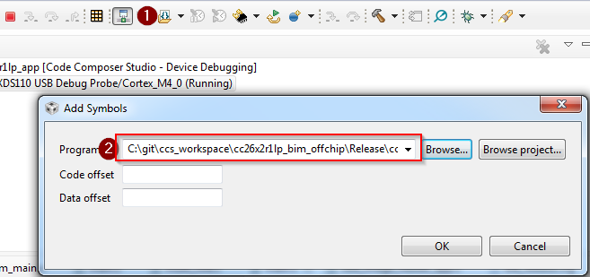
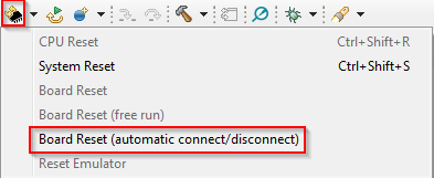
- Reset the device using the debugger. This will disconnect the target.
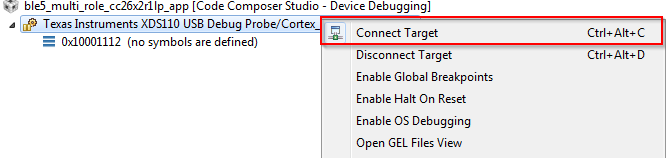
- Connect to the target:
- Set a breakpoint in
bim_main.c::Bim_checkImages()from the BIM project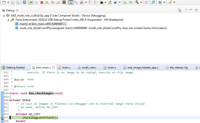
At this point you should be able to single step through the BIM code.
Quiz
Select the following statements that are true about BIM.
Debugging Slow OAD Download Speeds
One of the major improvements of the enhanced OAD profile are its utilization of MTU exchange and scalability of over the air block sizes. There are two major factors that determine the speed of an OAD download:
- The connection interval
- The OAD block size
The connection interval is set by the Central in the connection, but an update can be requested by the Peripheral device. Ultimately, it is up to the Central to set the connection parameters. To configure this request, open the SysConfig file and navigate to BLE → Peripheral Configuration → Connection Update Request Parameters. Here you can set the time for how long the Peripheral will wait from connection is formed until it sends the request, and the parameters to request.
In the case of the OAD sample applications, both project_zero and
simple_peripheral_oad_offchip will request a connection parameter update
about PZ_SEND_PARAM_UPDATE_DELAY or SP_PERIODIC_EVT_PERIOD after a link is
established based on a RTOS clock timeout.
One way to force a slow OAD is to prevent BTool from sending a connection parameter update at the start of OAD. In this case, the OAD Target device will send the parameter update that will slow the connection interval. This is normally a good practice for power savings reasons, but if an OAD is occurring this can be detrimental to speed.
- Connect to the OAD Target device via BTool.
- Navigate to the Over the Air Download tab
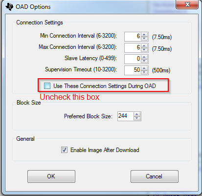
- Select the options pane and disable the check box near
Use These Connection Settings During OAD. This will prevent BTool from
sending a new connection parameter update at the beginning of an OAD.
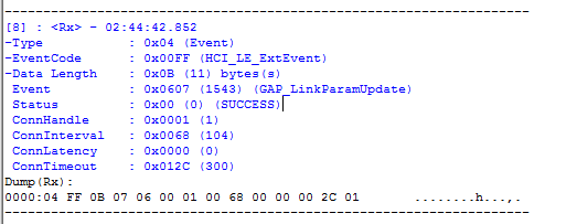
- Wait for the application to send its parameter update, this will appear as
an event in the logs.
- Start the OAD, observe slow speeds
- Cancel the OAD, re-check the box from step 3, and re-start the OAD.
- Repeat step 4
- After the parameter update is received, start the OAD via BTool. Observe that the speed will be much quicker.
Another contributing factor to the overall OAD throughput is the MTU size. The OAD block size is set by the OAD target device based on the MTU exchange. MTU exchanges are initiated by the GATT client device. There are three ways that the OAD session may potentially suffer from low throughput due to MTU size.
The OAD Target device is not built to support large MTU.
- This is controlled by the Maximum size of PDU (Found in SysConfig → BLE → General Configuration). This define can range up to 255.
- The formula for supported MTU based on the PDU size is
local supported MTU
= PDU_SIZE - L2CAP_HDR_SIZE
The OAD Distributor device does not support a large MTU, or the GATT client has not initiated an MTU exchange
- Just as locally the device must support large MTU, so must the peer, legacy or memory constrained peer devices may not support large MTU.
The OAD target is not reporting a negotiated MTU event to the OAD module.
- This is achieved by the the call to
OAD_setBlockSize()
- This is achieved by the the call to
The following steps will detail how to perform an OAD with smaller MTU size
- Open the BTool OAD Options window, and set Preferred Block Size to 24.
- Connect to the device and re-start the OAD.
- Observe that the total download time has greatly increased as the total blocks have increased to ~8000.
Quiz
What can an OAD Target device operating as a peripheral do to ensure high throughput and thus faster OAD speeds?
Task 5 – Bonus: Creating a Production Image
A production image is a single image that is made of all the images involved in an OAD system. In the case of off-chip OAD, the production image will consist of the app image and the BIM. Production images are desirable because they can be used to program devices in a test environment or production line using a single image. These images also must contain a valid image header.
Since the production image must contain a valid image header, the _oad.bin
image output by the TI OAD Image Tool must be used. This bin file contains the
app image. However, the app image cannot boot without a BIM included on the
device, so for a production image the app image must be merged with the BIM image.
To combine the images, we will use the SRecord tool.
The below steps assume that the Debug configuration of the BIM is used, and
the FlashROM_Release configuration of multi_role is used.
The steps can be easily modified or adapted to cover other configurations or
sample applications. The CCS workspace location will be referred to as
<CCS_WORKSPACE_LOC>
Download SRecord
Unzip the SRecord package into a location that will be referred to as <SREC_LOC>
Make sure your application and BIM have been built
Run the following command, you will need to replace <SREC_LOC> and <CCS_WORKSPACE_LOC> to match your environment. This will generate a production image titled
mutli_role_oad_production.hexin <SREC_LOC><SREC_LOC>/srec_cat.exe <CCS_WORKSPACE_LOC>/cc26x2r1lp_bim_offchip/Debug/cc26x2r1lp_bim_offchip.hex -intel <CCS_WORKSPACE_LOC>/ble5_multi_role_cc26x2r1lp_app/FlashROM_Release/ble5_multi_role_cc26x2r1lp_app_FlashROM_Release_oad.bin -bin -o multi_role_oad_production.hex -intelUse Uniflash to flash the
multi_role_oad_production.hexon the device, verify that the device is working and runs through a reset.
SRecord Examples
For more information and SRecord usage samples please see SRecord Examples
You have now created an OAD production image.
References
This work is licensed under a Creative Commons Attribution-NonCommercial-NoDerivatives 4.0 International License.