Introduction
This training will walk you through setting up the Easy Link Network Processor example, as well as using SmartRF Studio for RF evaluation. When you have completed the training you will be able to set up the TI-RTOS EasyLink AT command Network Processor example to run on supported hardware, e.g. the CC13xx or CC2640R2 LaunchPad.
This training lab is divided into the following tasks:
Task 1: Importing the EasyLink Network Processor Example
Task 2: Using the AT Command Interface to Configure RF Settings
Task 3: Exchanging Data Between Two Devices
Task 4: Exchanging Data Between a Device and SmartRF Studio
Task 5: EasyLink Packet Error Rate (PER) Test
Technical support
For any questions you may have, please have a look at the relevant E2E forums: TI Sub-1 GHz E2E Forum, TI 2.4 GHz Proprietary E2E Forum
Prerequisites
Background
- Basic knowledge about TI-RTOS and Code Composer Studio
- Some basic familiarity with embedded programming
Software
In order to start with this exercise you will need to download the correct Software Development Kit (SDK) for your LaunchPad.
For CC13x0:
- SimpleLink CC13x0 SDK 3.10 or later. Note: SysConfig is not available for this device.
For CC13xx/CC26xx:
- SimpleLink CC13xx CC26xx SDK 3.30 or later. (Any older version does not support SysConfig)
For CC2640R2:
- SimpleLink CC2640R2 SDK 3.10 or later. Note: SysConfig is not available for this device.
The following software applies for both device families:
Code Composer Studio 9.2 or higher. (Any older version does not support SysConfig)
Sensor Controller Studio 2.4.0 or later.
Tera term or any other equivalent terminal program
Hardware
- 2 x CC13xx LaunchPads or 2 x CC2640R2 LaunchPads.
Team Up!
Two LauchPads are required in order to transmit and receive data between them. If in a group, you may work in pairs. Then each student will only need one LaunchPad.
Note
This lab can be performed using either CC1310, CC1350, CC1312, CC1352 or
CC2640R2 LaunchPads.
The training material is based on a CC1350 LaunchPad, but for this
training the steps and procedures are the same regardless of type of device.
If you need to make adjustment based on the device you are
using, it will be highlighted during the training.
Group training additional requirements
Make sure to always use your designated frequency, to avoid interfering with other students' operations
Frequency allocation
If you are part of a group training, please ask the instructor for a unique frequency to use during this lab.
For simplicity, it is possible to use a base frequency (2440.0, 915.0, 868.0, 433.0), allocate a running number to each of the students and have each student multiply their number by 100 kHz channel spacing. For example, student #5 would then use 868 + 0.1*5 = 868.5 MHz.
EasyLink API
The RF core has a dedicated driver called the TI-RTOS RF driver. This is used for all interaction with the RF core. The EasyLink API is a simple abstraction layer on top of the RF Driver and is intended as a starting point for customers creating a proprietary protocol or application using the Sub1-GHz or 2.4 GHz frequency band.
EasyLink Examples
The following examples can be found in the resource explorer under the corresponding device SDK:
- rfEasyLinkTx
- rfEasyLinkRx
- rfEasyLinkEchoTx
- rfEasyLinkEchoRx
- rfEasyLinkNp
- rfEasyLinkListenBeforeTalk
- rfWsnConcentrator
- rfWsnConcentratorOadServer
- rfWsnNode
- rfWsnNodeExtFlashOadClient
- rfWsnNodeIntFlashOadClient
OAD = Over the Air Download.
For instructions on using the CC13xx and CC2640R2 MCU SDK examples and the EasyLink API, refer to the CC13xx Proprietary RF User's Guide.
Note
The EasyLink layer does not support any regional RF conformance such as Listen Before Talk, required for the license-free frequency band. Customers need to add support for the regional conformance features that their product requires under the EasyLink API.
Easylink Alternatives
If you do not wish to use the EasyLink abstraction layer, there is also the option to do simple packet RX/TX using the TI-RTOS RF driver directly. For more info, see SimpleLink Academy lab Proprietary RF - Basic RX and TX.
The API
EasyLink programming is utilized through a set of API function calls, encapsulating the required RF operations.
API
The EasyLink API is documented both online and offline in the Proprietary RF User's Guide and is briefly presented here for reference:
| Generic API function | Description |
|---|---|
| EasyLink_init() | Inits and opens the RF driver |
| EasyLink_transmit() | Blocking transmit |
| EasyLink_transmitAsync() | Nonblocking transmit |
| EasyLink_receive() | Blocking receive |
| EasyLink_receiveAsync() | Non-blocking receive |
| EasyLink_abort() | Aborts a non-blocking call |
| EasyLink_GetIeeeAddr() | Gets the IEEE address |
| EasyLink_EnableRxAddrFilter() | Enables/disables RX filtering on the address |
| EasyLink_SetFreq() | Sets the frequency |
| EasyLink_GetFreq() | Gets the frequency |
| EasyLink_SetRfPwr() | Sets the TX power |
| EasyLink_GetRfPwr() | Gets the TX power |
| EasyLink_getAbsTime() | Gets the absolute radio time |
| EasyLink_setCtrl() | Sets advanced configuration options |
| EasyLink_getCtrl() | Gets advanced configuration options |
EasyLink Network Processor
In the EasyLink Network Processor project, the EasyLink API is also exposed via an AT Command Interface such that it can be exercised over serial transport by a host software (running on an PC, MPU or MCU) or manually by using a serial terminal emulator. This manual approach is used and demonstrated in the tasks below.
Task 0: Label your LaunchPads
Label each of your LaunchPads with its XDS Device ID, as described here.
Label one LaunchPad as "A" and the other as "B". These labels will be referred to throughout this lab. It is recommended to use a non-permanent marking for this (e.g. sticky notes), as these labels may only be relevant for this specific lab.
Task 1: Importing the EasyLink Network Processor Example
In this task we will use Code Composer Studio (CCS) to import, build and flash the EasyLink Network Processor example onto the LaunchPad platform.
CCS Alternatives
While the current lab is designed for CCS, it may be useful to note that the various TI-RTOS examples are also compatible with IAR Embedded Workbench ( see here), with GCC as well as with the Cloud based version of Code Composer Studio.
Import the Example Project
Open CCS
To open Resource Explorer, click "Browse examples" in the Getting Started pane, or open it from the menu under View → Resource Explorer
Attention
Do not open Resource Explorer Classic (if it is an available option). In this lab we will be working with the new Resource Explorer.
If this is the first time running Resource Explorer after installing the SimpleLink SDK, make sure it finds the SDK, and let it import it.
Depending on the device you are using:
- For CC13x0, expand the elements: Software → SimpleLink CC13x0 SDK - v:x.x.x.x → Examples → Development Tools → CC13x0 LaunchPad → EasyLink → rfEasyLinkNp → TI-RTOS
- For CC13xx, expand the elements: Software → SimpleLink CC13xx CC26xx SDK - v:x.x.x.x → Examples → Development Tools → CC13x2 LaunchPad → EasyLink → rfEasyLinkNp → TI-RTOS
For CC2640R2, expand the elements: Software → SimpleLink CC2640R2 SDK - v:x.x.x.x → Examples → Development Tools → CC2640R2 LaunchPad → EasyLink → rfEasyLinkNp → TI-RTOS
Make sure to import the correct example!
When browsing the Resource Explorer, make sure to select the SDK that corresponds to the device you are using. This training assumes the CC1350 LaunchPad is used which will be reflected in images and file names.
Select CCS Compiler (i.e. click on CCS Compiler in the folder-tree view on the left). Your view should look similar to this:
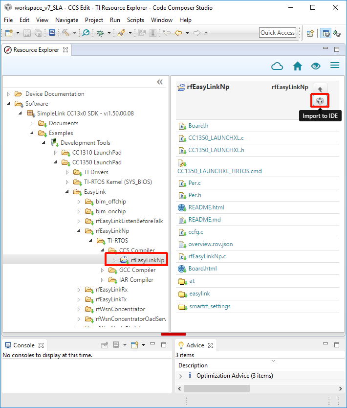
Click on Import to IDE icon in top right corner (see image above).
You have now imported the rfEasyLinkNp example project
There should now be a new project in the Project Explorer called rfEasyLinkNp_CCxxxx_LAUNCHXL_tirtos_ccs:
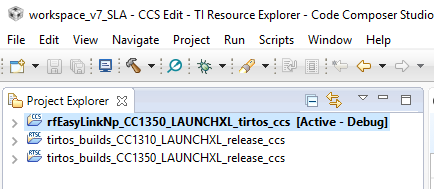
Note
The TIRTOS kernel is now included as a separate project imported with the example project - In the screen capture above, see the tirtos_builds_CCxxxx_LAUNCHXL_release_ccs project. The TIRTOS kernel project is specific to the board type and compiler and shared by all examples for that Board type / compiler.
Build and flash the Example
Connect one LaunchPad to your PC via USB. This will enumerate two serial COM ports on the PC, one of them will have the word "UART" in its name string - this is referred to as the Application UART.
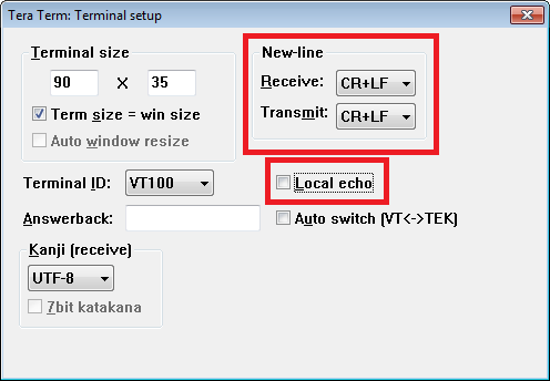
Connect a PC terminal emulator program (e.g. Tera Term) to the LaunchPad via the Application UART port, using the configuration 115200,8,N,1.
Configure the terminal program to add <LF> character to each incoming and outgoing <CR> character, and disable local echo of outgoing characters
In CCS, Build and download the example by clicking "Debug" (shortcut F11):

Run the example by clicking on the Resume button (F8).

Verify the program operation:
Watch the terminal program on the PC
You should now see "EasyLink" and version information being printed to the terminal via UART. The device is now ready to accept AT commands.
Terminate the CCS debug session (by clicking the red square icon)
If working in pairs, or this is already the second LaunchPad that you are programming, skip ahead to Task 2. Otherwise, perform the next steps to program the second LaunchPad.
Disconnect the terminal program from the first LaunchPad
Disconnect the first LaunchPad from the PC
Repeat the procedure above from step 1, using the second LaunchPad this time.
Task 2: Using the AT Command Interface to Configure RF Settings
The AT Command Interface uses ASCII characters, so that a user can easily send and receive the commands through a terminal emulator. Additionally, it makes use of framing characters, to enable a host software to send and receive the AT commands programmatically.
The frame format is shown below:
| Start of Frame | Command Type | Command ID | parameters | End Of Frame |
|---|---|---|---|---|
| "AT" | "P" or "+" | {i} | {xxxx} | <CR> |
<CR> represents Carriage Return, i.e. ASCII character 0x0D. When typing in the commands in a terminal, simply press ENTER to execute.
Avoid using backslash and similar keys as they can be interpreted as command characters.
Keep in mind that the EasyLink API is documented both online and offline in
the Proprietary RF User's Guide. The AT interface documentation can be found
inside the README.html file found inside the rfEasyLinkNp example
project.
Team work?
If working in pairs, make sure both students use the same RF settings, including the frequency that was allocated to one of you by the instructor.
At this point, you should have a terminal emulator running, already connected to a LaunchPad.
In order to initialize the radio to 2-GFSK 50kbps mode send the following command using the AT interface via the serial port:
AT+i 0AT+i – Used to initialize the radio.
Make sure to select a supported mode
Depending on the device, different modes are supported. Make sure to select a mode that works for your device. If using the CC2640R2 LaunchPad , you can for example use mode 2, 5 or 6. For this training, it is recommended to use mode 5.
Arguments of the i/I command
For CC13xx devices only:
- 00: 2-GFSK, 50 kbps
- 01: For 625 bps Long Range Mode
04: For 5kbps SimpleLink Long Range Mode
For CC2640R2 devices only:
- 05: For 100kbps 2.4G 2-GFSK Mode
06: For 250kbps 2.4 2-GFKS Mode
For all devices:
- 02: For user defined from smartRF_settings.c/h
Verify the response
The device shall respond with "OK".
Set the frequency to your (your team's) allocated frequency, by sending the FR command (in the example below, it is used to set the frequency to 868.0MHz)
ATPFR=868000000ATPFR: Used to set the communication frequency/channel of the radio.
If you omit this command...
The default frequency is 868.0 MHz for most examples. Depending on the LaunchPad used, the default center frequency used will be different. For example, the CC2640R2 LaunchPad examples operates at a 2440 MHz center frequency and the CC13xx 433 MHz LaunchPad examples operate at 433 MHz.
Find out what the output power is set to, by sending the following command
ATPPW?ATPPW: Used to set/get the radio output power.
See the response
The radio shall reply with the configured output power setting, followed by "OK" (without any spaces), e.g.
12OK.Enabling Maximum Transmit Power
With the default ccfg settings, the Sub-1 GHz transmit power is limited by the DC/DC converter configuration to 12.5 dBm (displayed as 13). See the EasyLink API on how to enable higher transmit power.
When using CC2640R2, the maximum output power is 5 dBm.
If working in pairs, or you have already completed the above steps for the second LaunchPad, skip ahead to Task 3. Otherwise, perform the next steps:
Connect the second LaunchPad to the PC (leave the first LaunchPad connected)
Open another terminal emulator instance and connect it to the second LaunchPad using its application UART. Use the same UART configuration and terminal configuration as before.
Repeat the procedure starting at step 1 above, this time working with the second LaunchPad.
Task 3: Exchanging Data Between Two Devices
Put the LaunchPad labeled "A" in RX mode:
AT+RXAT+RX: Used to set the radio in RX mode.
Note
AT+RX initiates reception of a single packet. To receive another packet, issue AT+RX again.
Send some data from the other ("B") LaunchPad:
AT+TX Hello World!AT+TX: Used to send data.
Did it work?
Look at the terminal of the receiver, and verify you got the text that was sent.
Task 4: Exchanging Data Between a Device and SmartRF Studio
Next we will send packets from a LaunchPad connected to SmartRF Studio to another LaunchPad running the EasyLink NWP (NetWork Processor) example.
As a starting point, you should have LaunchPad "A" connected to a terminal and configured as in Task 2 above (This is probably already the case after completing the tasks above).
Disconnect the terminal emulator from LaunchPad "B" (if currently connected), while keeping this LaunchPad connected to the PC.
Put LaunchPad "A" in RX mode:
AT+RXAT+RX: Used to set the radio in RX mode.
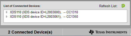
Open SmartRF Studio and double-click LaunchPad "B" in the device listing ( identify it by its XDS Device ID), to open up the Device Control Panel. If the required LaunchPad is not shown in the device listing, click on the green arrow next to Refresh list.
In the mode selection window, select Proprietary mode
Update the RF parameters to match the ones you are using on LaunchPad "A", which is running the EasyLink device. Additionally, make sure you adhere to the EasyLink Frame format:
- Look back to what mode you selected using the "AT+i x" command - double-click the respective configuration option in the Typical Settings pane. If needed, adjust the settings manually to match your device.
- You also used "ATPFR" to set the frequency. Enter the same frequency in the RF Parameters pane.
Enable Address and set it to 00 (which is the default in EasyLink), send Text (ASCII), and do not include a sequence number - see highlighted fields in the following screen capture:
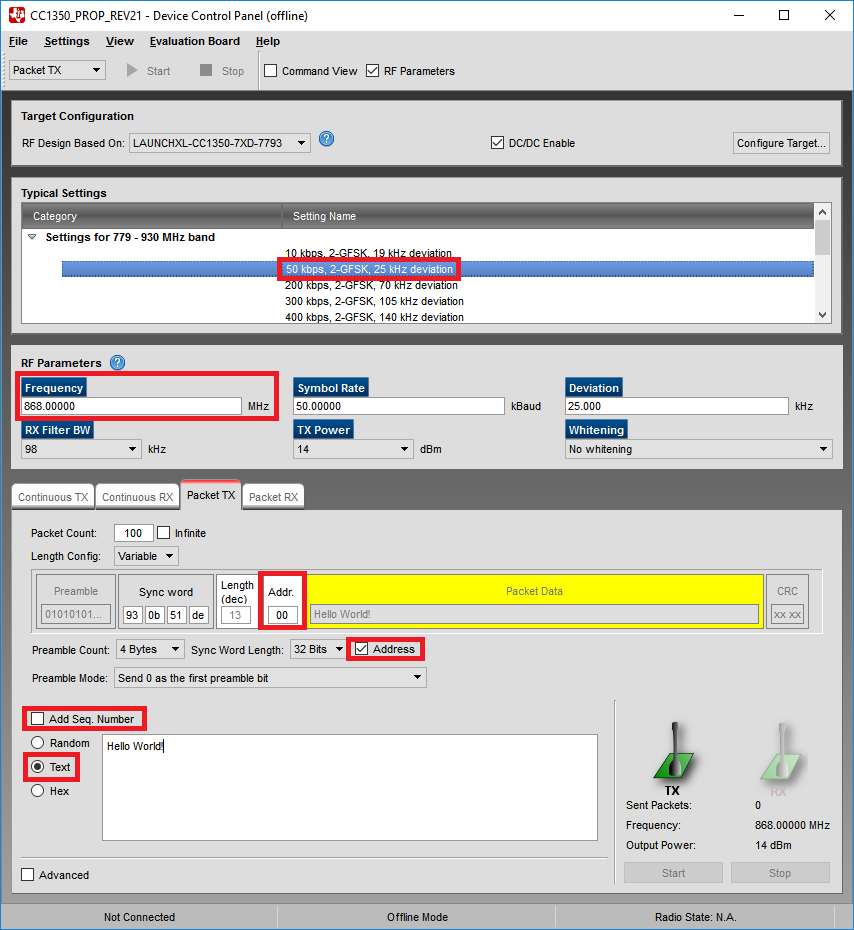
Click on the Start button in the TX tab to send the data.
Does it work?
Verify that you received the data on the device running EasyLink NWP ( LaunchPad "A"). Remember that the AT+RX command only receives a single packet. To receive another packet, run the AT+RX command again.
Now do it the other way around: send data from your EasyLink device and receive it using SmartRF Studio. When configuring the SmartRF Studio RX mode, make sure to set it to Text mode, disable sequence number, enable address check, and set the address to 0.
Task 5: EasyLink Packet Error Rate (PER) Test
In this task we will be setting up a PER test between two devices running the EasyLink NWP example.
Supported tests
The EasyLink AT interface supports the following test modes:
Carrier Wave
Modulated Signal
PER TX
PER RX
Initialize two NWP setups
As a starting point, you should have the two LaunchPads running the NWP firmware and connected to terminals. If any of the LaunchPads is connected to SmartRF Studio, close SmartRF Studio and reset the LaunchPad (e.g. by pressing its reset button), to restart the firmware execution.
Initialize both devices to use 50kbps 2-GFSK mode:
AT+i 0AT+i: Used to initialize the radio.
If in a group, make sure to use your allocated frequency on both LaunchPads. For example:
ATPFR=868000000ATPFR: Used to set the communication frequency/channel of the
radio.
The number of packets to process during the test is determined by the
PPparameter. If this parameter is set to 0, then the test will run indefinitely.Configure the test on both LaunchPads to run for 100 packets:
ATPPP=100ATPPP: Read/Write number of PER TX/RX packets
Check yourself
Make sure you entered the commands above on both of the LaunchPads.
PER Receiver
Select one of the LaunchPads (e.g. "A") to be the receiver. Start a PER RX test (test mode 4), by using:
ATPTM=4ATPTM: Read/Write test mode.
Ready for RX
The device enters RX and accepts 100 packets.
PER Transmitter
Start a PER TX test (test mode 3) on the other LaunchPad (e.g. "B"):
ATPTM=3ATPTM: Read/Write test mode.
Test is running
The device starts TX and transmits 100 packets.
Interpreting the results
While the test is running, the TX device's terminal should look like this:
TPER: 00
TPER: 01
TPER: 02
...
and the RX device should show lines similar to these:
RPER: 00, 0001, 0000, -31
RPER: 01, 0002, 0000, -31
RPER: 02, 0003, 0000, -31
...
The columns reported by the RX device correspond to:
RPER: Sequence Number, Pass Count, Fail Count, RSSI
The sequence number is sent from the TX PER device, and is expected to increment by 1 for each packet. Pass Count increments every time a correct packet is received. Fail Count increments every time an incorrect packet is received.
Once the test is finished, you should see the response below on both the TX and RX devices:
Done OK
Make some practical measurements!
Do some range testing: move around in the building with one of the devices, repeat the PER test from different locations and compare the results.
Bonus Tasks
The instructions of the bonus tasks are much less detailed than those of the main tasks above. To complete the bonus tasks, you may need to refer to the SDK documentation.
The bonus tasks can be done in any order.
Bonus Task 6: Long Range Mode PHY
Change the PHY settings to use the Long Range Mode (LRM), then do some more PER testing. Does the range improve?
LRM is only supported by CC13xx devices
If using the CC2640R2 LaunchPad for this training, skip this section.
Bonus Task 7: Explore the AT Command Interface
Explore what else you can realize by using the EasyLink AT commands API. Remember, the EasyLink API is documented in the Proprietary RF User's Guide and the AT commands here.
References
CC13xx Overview – Available here
CC2640R2 Overview – Available here
CC13x0 and CC2640R2 Technical Reference Manual – Available here
CC13x2 Technical Reference Manual – Available here
EasyLink API: Available in the Proprietary RF User's Guide.
This work is licensed under a Creative Commons Attribution-NonCommercial-NoDerivatives 4.0 International License.