Introduction
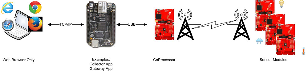
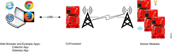
The TI 15.4-Stack Linux SDK example applications helps developers create ultra-low power, very long-range, star-topology network solutions. The TI 15.4-Stack Linux SDK includes the Collector and Gateway Example Applications (in addition to others; See the TI 15.4-Stack Embedded Developer’s Guide for more details). The Linux Collector Example Application interfaces over UART with a CC13x2 LaunchPad™, which acts as a MAC CoProcessor (CoP). The Collector Example Application implements a full-function device which performs the functions of a network PAN coordinator (starting a network and permitting devices to join this network) and also provides an interface for monitoring and collecting sensor data from one or more sensor devices. In addition, the Collector Gateway Example Application provides a socket server interface to the Linux Gateway Application.
The Linux Gateway Application, implemented using the NodeJs framework, connects as a client to the socket server created by the Linux Collector. It then establishes a local web server, to which the user can connect through a web browser, to monitor and control the network devices. The Collector and Gateway Example Applications, constitute together a complete IEEE 802.15.4 to IP Bridge, and is a great starting point to create Internet of Things (IoT) applications based on TI 15.4-Stack.
This lab makes use of pre-built binary files, so no coding or building is required. It provides detailed instructions to assist developers set up and understand the principles behind this working demo of a Linux-Collector-based star network of sensors.
Task 1: Prepare the sensor
Task 2: Prepare the MAC CoProcessor
Task 3: Install the TI 15.4-Stack Linux Gateway SDK
Task 4: Prepare the host
Task 5: Run and use the solution
Technical support
For any questions you may have, please have a look at the relevant E2E forum - TI Sub-1 GHz E2E Forum
Supported Devices/SDKs
This lab is intended to be used with the newest SDKs for each of these TI devices:
| TI Device | SDK |
|---|---|
| CC13x0 | SIMPLELINK-CC13X0-SDK |
| CC13xx & CC26xx | SIMPLELINK-CC13XX-CC26XX-SDK |
Note
2.4GHz operation/CC26x2 is not supported in this release
Prerequisites
Background
Some basic Linux knowledge is required for performing this lab.
Software
- UniFlash
- The corresponding SDK(s) from the list above
- TI 15.4-Stack Linux Gateway SDK
- PROCESSOR-SDK-LINUX-AM335X SD Card Image v. 05.03.00.07 for BeagleBone Black (Only if using Embedded host - see Task 4 below)
- (Optional) You may also use the Linux Debian image for your specific Beaglebone. Use the Stretch IoT (without graphical desktop) image.
- Tera term or any other equivalent terminal program
Hardware
- 2 x Compatible LaunchPads, refer to the Supported Devices/SDKs section
- 2 x USB Cables
- Wired network access (e.g. Wi-Fi router with an available Ethernet connection)
- Host platform - either one of:
- Embedded host platform
- BeagleBone Black rev. C (other revisions of the BBB may be compatible, but were not tested)
- Compatible 5v Power adapter
- Ethernet cable
- TTL-232R-3V3 USB to TTL Serial cable by FTDI, AKA simply as FTDI cable (optional)
- PC host platform
- A PC or a virtual machine connected to the local network and running ubuntu
- A PC or a virtual machine connected to the local network and running ubuntu
- Embedded host platform
- A PC or a virtual machine running ubuntu 18.04 LTS 64bit (required, even if using an embedded host), for extracting the pre-compiled gateway binaries from the Linux SDK installer (other Linux versions may also be compatible but were not tested)
- A Windows PC for running SmartRF Flash Programmer 2 and for installing the SimpleLink CC13xx/CC26xx SDK
Two host platform options
The TI 15.4-Stack Linux Gateway is compatible out-of-the-box with both embedded host (the BeagleBone Black) and PC host (see Hardware Prerequisites above).
Using a PC host may provide easier development and debugging capabilities. If you already have an available ubuntu PC or virtual machine, it will also provide a faster bring-up time, as you will not need to re-install the host environment. On the other hand, while using the BeagleBone as a host may involve some extra steps for setting it up, it provides a more realistic environment, closer to the embedded target product.
Note
This lab can be performed using any CC13xx LaunchPad. The training material is based on CC1312, so if using any other CC13xx device, all references to CC1312 in text and screenshots should be referred to as your particular board.
Task 0: Label your LaunchPads
Label each of your LaunchPads with its XDS Device ID, as described here.
Additionally, label one LaunchPad as "Sensor" and the other as "MAC-CoP". These labels will be referred to throughout this lab. It is recommended to use a non-permanent marking for this (e.g. sticky notes), as these labels may only be relevant for this specific lab.
Task 1: Program the "Sensor" LaunchPad
It is assumed you have already installed your corresponding SDK from the supported device list section. If not, please install it now.
Complete Task 2 of the Sensor and Collector - TI 15.4-Stack Project Zero
Skip the last two steps of the Sensor and Collector - TI 15.4-Stack Project Zero!
Make sure you did not follow the debugging and downloading of the program, we will do this later.
Connect the "Sensor" LaunchPad to the Windows PC.
Run UniFlash, and perform the following steps:
Uniflash will automatically find any LaunchPads that are connected to your PC:
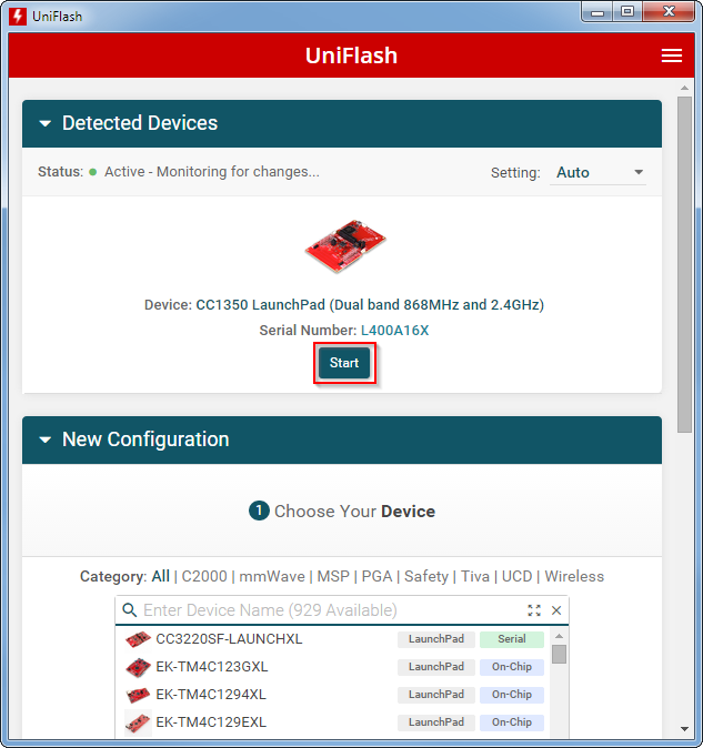
If more than one LaunchPad is connected to the pc:
Make sure to select the correct LaunchPad when programming the firmware: Compare the XDS Device ID that you written on the LaunchPad in Task 0 to the device ID shown in the serial number field of the image above.
Go to the
Settings & Utilitiestab in Uniflash and erase all unprotected sectors: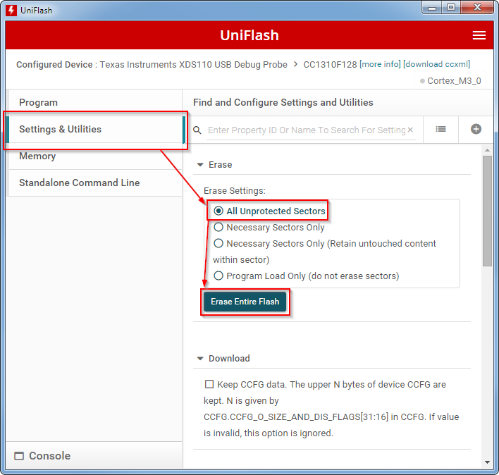
Before programming the device, change the Erase settings back to
Necessary Sectors Only (Retain untouched content within sector), like below: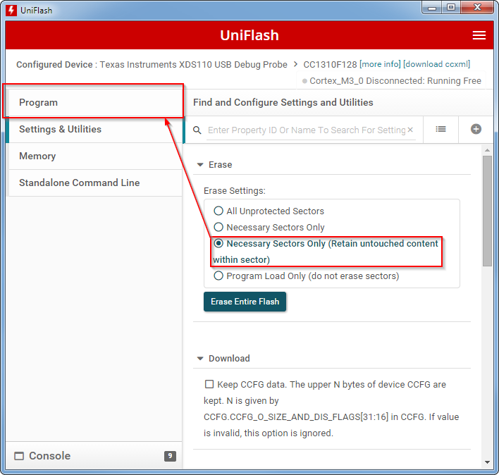
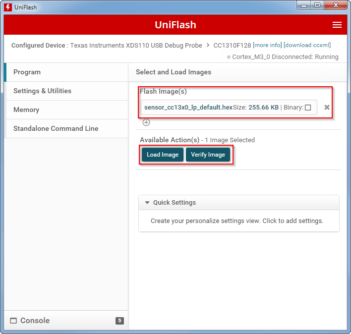
In the Program tab, under Flash image(s), browse to the pre-built sensor hex file, located at:
C:\ti\<workspace_path>\sensor_<your_target_board>_tirtos_ccs_syscfg\release\sensor_<your_target_board>_tirtos_ccs_syscfg.hexWhere
<workspace_path>corresponds to your workspace,<your_target_board>corresponds to the LaunchPad you are using for this lab.Make sure to first Load Image and then afterwards Verify Image
Task 2: Program the "MAC-CoP" LaunchPad
Follow the steps above to program the "MAC-CoP"" LaunchPad using the respective hex image located at:
C:\ti\<sdk_path>\examples\rtos\<your_target_board>\ti154stack\hexfiles\coprocessor_<your_target_board>_tirtos_ccs.hexWhere
<sdk_path>corresponds to your SDK,<your_target_board>corresponds to the LaunchPad you are using for this lab.
NOTE
For CC2652P devices, hex images can be found in:
C:\ti\<sdk_path>\examples\rtos\CC1352P-4\ti154stack\hexfiles\coprocessor_<your_target_board>_tirtos_ccs.hex
Task 3: Install the TI 15.4-Stack Linux Gateway SDK
Download TI 15.4-Stack Linux Gateway SDK to your ubuntu machine. The SDK package comes in the form of a Linux executable, named ti15.4stack_linux_x64_x_xx_xx_xx.run (the x_xx… will show the actual version number).
Assign execute permissions to the installer, and then execute it:
chmod +x ti15.4stack_linux_x64_x_xx_xx_xx.run
./ti15.4stack_linux_x64_x_xx_xx_xx.run
Run the Gateway SDK installer
Follow the installer instructions, accept the license agreement and select a destination path, to extract the SDK content to the Linux filesystem. Wait for the installer to finish.
Task 4a: Prepare the embedded host
This tasks walks through setting up the BeagleBone Black as an embedded host for the TI 15.4-Stack Linux Gateway. If you are using a ubuntu linux PC (or virtual machine) as a host, rather than a BBB, please skip this task and go straight to the next task.
Doing stuff differently
Some of the tasks below can be done on either a Windows or a Linux PC (don't get confused with the host platform discussed above - here we talk about the PC used for performing the lab). For simplicity, for such tasks, only Windows instructions are provided in detail. If you feel you do know how to perform certain tasks on a Linux PC and prefer to do so, please go ahead and try it!
Program the SD card with an appropriate linux image using the following steps, which can be done on either a windows or a linux machine:
Download the prebuilt TI processor SDK SD card image file, am335x-evm-linux-05.03.00.07.img.zip or the Debian Stretch IoT image.
Follow these instructions to program the microSD memory card with the above image:
For Windows instructions, follow this wiki
For Linux instructions, follow this wiki
Connect the FTDI cable to header J1 on the BeagleBone - the black wire should be connected to the pin marked with a dot.
Connect the USB connector of the FTDI cable to the Windows PC.
The FTDI cable should be automatically enumerated as a serial device. If not, please install the required drivers.
Run a terminal program on that PC (e.g. Tera Term), and connect it to the FTDI cable's serial port. Configure it to use 115,200 kbps, 8 data bits, No parity, 1 stop bit, No flow control.
Boot the BBB using the newly prepared SD card:
Make sure no cable is connected to the BBB (e.g. power, USB) other than the FTDI cable.
Connect the BBB to your network using the Ethernet cable
Insert the SD card into the BBB
Press and hold the Boot Select button, which is located near the SD card slot. Note that the boot button is detected only at initial power on, and not on other types of reset:
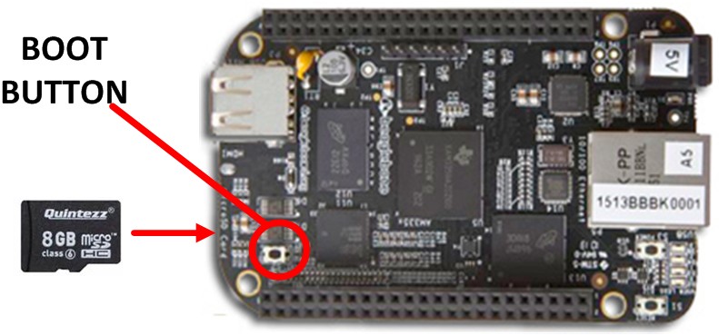
While holding the Boot button, provide power to the BBB by connecting the 5v power supply
Wait a few seconds, then release the Boot button. In about 5 to 15 seconds the LEDs should begin to blink.
Be patient :-)
The first boot from a freshly formatted SD card takes about 1 to 2 minutes longer, during this extended time the BBB Linux distribution performs some one-time-only steps.
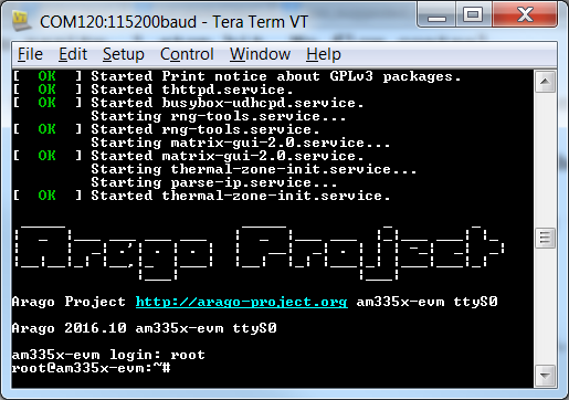
Once the BBB is up and running, you should see the Arago Project wellcome message, and a prompt to enter enter the user name. Type in the user name root and press ENTER:
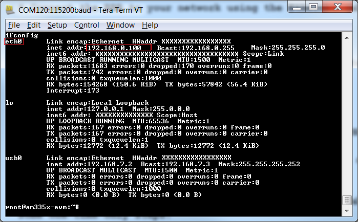
Use the ifconfig command to get the ip address assigned to the BBB for the Ethernet connection (You will need this address in order to transfer files to the BBB and to open additional terminal windows):
Open another terminal window, and connect to the BBB using SSH to the ip address you found above. Use user name root and no password. Close the older terminal window (that is connected via the FTDI cable).
Why?
The console connection over the FTDI cable provides some extra level of debug traces that may be useful during development, but may make user interaction less comfortable.
Locate the file bbb_prebuilt.tar.gz in the Linux Gateway SDK that you installed in Task 3. This file is under the prebuilt directory in the main SDK folder (by default, the SDK is extracted to ~/ti/simplelink/ti-15.4stack-x.xx.xx.xx).
Copy this file from the ubuntu machine to the BBB file system - you may use a USB thumb-drive to do so. Alternatively, if the BBB and the ubuntu machine (where the gateway SDK is installed) are on the same network, you can use scp for transferring the file, by executing the following commands in the ubuntu machine:
First, change your working directory to the directory where the file is located, then call scp (replace <bbb-ip-address> with the actual ip address of the bbb):cd ~/ti/simplelink/ti-15.4stack-x.xx.xx.xx/prebuilt scp bbb_prebuilt.tar.gz root@<bbb-ip-address>:/home/root/Copy the pre-built files onto the BBB
- On the BBB, extract the bbb_prebuilt.tar.gz file by executing the following commands
cd ~/
tar -xvf bbb_prebuilt.tar.gz
Extract the pre-built content
Task 4b: Prepare the PC host
If you are using a BeagleBone Black as a host, please skip this task and go straight to the next task.
Assuming you log in to the ubuntu PC as a standard user and not as root, you will need to execute the following command to gain access to the serial port used for communicating with the LaunchPad:
sudo adduser $USER dialoutAllow access to the LaunchPad's serial port
For the command above to take full effect, please reset your ubuntu PC after executing that command.
Use the ifconfig command to get the ip address assigned to the Ubuntu PC for the Ethernet connection (You will need this address in order to transfer files to the Ubuntu PC)
Locate the file host_prebuilt.tar.gz in the Linux Gateway SDK that you installed in Task 3. This file is under the prebuilt directory in the main SDK folder (by default, the SDK is extracted to ~/ti/simplelink/ti-15.4stack-x.xx.xx.xx).
Copy this file from the ubuntu machine to the Ubuntu PC file system - you may use a USB thumb-drive to do so. Alternatively, if the ubuntu machine (where the gateway SDK is installed) are on the same network, you can use scp for transferring the file, by executing the following commands in the ubuntu machine:
First, change your working directory to the directory where the file is located, then call scp (replace <ubuntu-ip-address> with the actual ip address of the ubuntu PC):cd ~/ti/simplelink/ti-15.4stack-x.xx.xx.xx/prebuilt scp host_prebuilt.tar.gz root@<ubuntu-ip-address>:/home/root/Copy the pre-built files onto the Ubuntu PC
- On the ubuntu PC, extract the host_prebuilt.tar.gz file by executing the following commands
cd ~/
tar -xvf host_prebuilt.tar.gz
Extract the pre-built content
Task 5: Run and use the gateway
In this chapter, the term host is used in reference to either the BBB or the PC host. In places where a distinction should be made, it will be clearly noted.
Connecting the MAC CoProcessor to the host
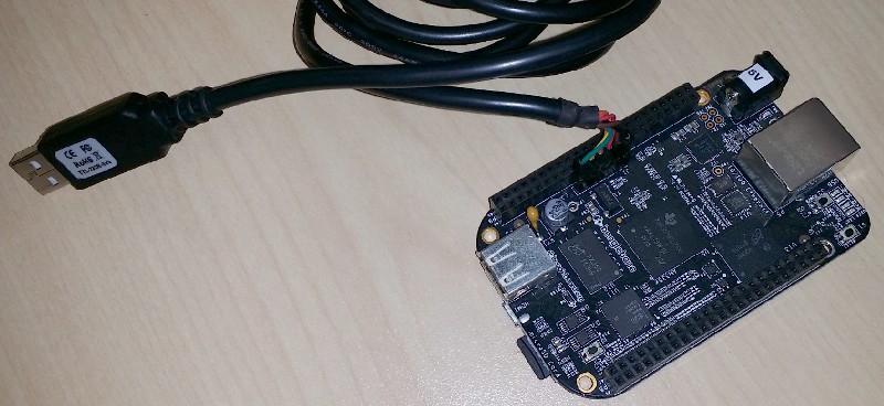
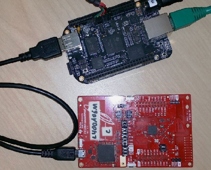
Plug-in the "MAC-CoP" LaunchPad to the host using a USB cable. If you are using the embedded host option, it should look like this:
Wait a few seconds, and then check to see if the LaunchPad enumerated successfully as 2 serial ports, by entering the following command in the host terminal window:
ls –l /dev/ttyACM*Verify correct enumeration of "MAC-CoP"
Did it work
When the "MAC-CoP" LaunchPad has enumerated successfully, you should see the following output. If you don't, keep on reading for a possible solution.
/dev/ttyACM0 /dev/ttyACM1Successful enumeration output
What if it does not work?
If you do not see any new serial port enumerated after plugging in the "MAC-CoP" LaunchPad, wait a few more seconds and try entering the command above again.
It is also possible that the LaunchPad had enumerated using different serial device names (e.g. /dev/ttyACM3). If this is the case, you will need to update the gateway configuration file, which assumes /dev/ttyACM0 by default. To do this, open the file prebuilt/bin/collector.cfg, look for ttyACM0 and update this value accordingly. Note that the LaunchPad enumerates as two separate serial devices - please choose the one with the lower number suffix. If the next steps fail, you may return to this step and try the other serial device name instead.
Starting the Application – Starting the Network
The PREBUILT directory contains a simple shell script called run_demo.sh, which is all you need to get everything up and running.
Change the working directory on the host according to the host platform. If using a PC host, replace the x.xx... with the actual SDK version number:
cd ~/prebuiltIf using BBB host
cd ~/ti/simplelink/ti-15.4stack-x.xx.xx.xx/prebuiltIf using PC host
Execute the following commands on the host. The rm command is for getting rid of any pre-existing network configuration, and is only needed if you have already ran the gateway on this BBB before. The sh script starts the TI 15.4-Stack Gateway and Collector Application.
rm bin/nv-simulation.bin
./run_demo.sh
Start the TI 15.4-Stack Linux Gateway
What to expect
The gateway will start up and show some informational messages, then it will brings back the command prompt while continue running in the background. If using BBB host, the terminal window will look similar to this to the image below. If using a PC host, in addition to similar traces in the console, a web browser will automatically be opened and connected to the collector application (as discussed later on).
Note that the message Connected to App Server may appear a few seconds after the command prompt is displayed.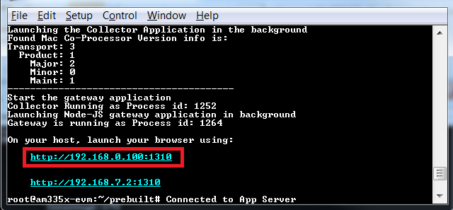
The integrated web server is now accessible via the links provided in the console traces. If using a PC host, a web browser will automatically be opened and connected to this web server. If using BBB host, select the link accessible from your PC (depending on your PC's IP address), open a web browser on the PC, enter this link in the address line and press ENTER. The link you should use will have the same IP address as you discovered earlier with ifconfig, with an addition of a specific port number - 1310. When copying the link to your web browser, make sure to include the complete link, including the port number. If you omit the port number, the browser will default to port 80, which may lead to a different web page which is outside the scope of this lab.
How it should look
Your web browser should now be displaying a page similar to this:
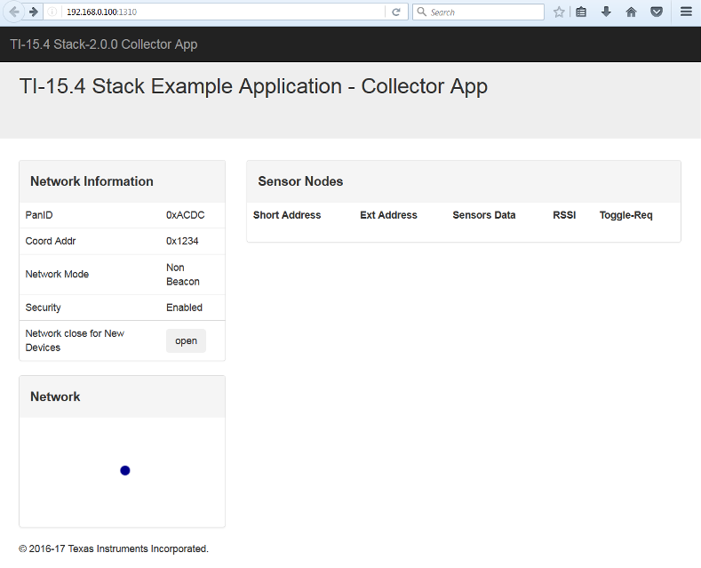
Modifying the network parameters
Notice the PanID value in web page you just opened. This value, as well as the RF channel, the Beacon Order and other RF-related parameters can be easily changed by editing the file prebuilt/bin/collector.cfg, then rebooting the BBB and rerunning the gateway as explained above.
Adding sensor device(s) to the network
When the gateway example application starts for the first time, no devices are present in the Sensor Nodes list and the network is closed for joining meaning it will not accept new device connections.
Connect the "Sensor" LaunchPad to an available powered USB port, or USB power adapter.
Reset the sensor node to factory defaults, by pressing and holding Button 2, then pressing and releasing the Reset button while Button 2 is still being pressed and then releasing Button 2. Following reset, the sensor device will automatically try to connect to an available network.
Click the Open button on the web page, to open the network for new devices. The sensor devices will connect to the gateway/collector after a few seconds
What to expect
Once the "Sensor" LaunchPad is connected to the network, its red LED (DIO6) will light up, and the Sensor Nodes list will show this newly added device.
If it does not connect...
...simply press the "Sensor" LaunchPad's reset button again - no need to press Buttons 1 and 2 this time.
Monitoring sensor data and sending control commands
Watch the web interface you opened in the web browser.
Sensor data reports
After the new device is added to the network, its short and extended addresses should appear in the device list. At the beginning, the data fields are displayed as — (hyphens), indicating no data. 1-2 minutes later, sensor reading values will also be displayed (the exact interval is configured in the Collector application using a #define value - see the TI 15.4-Stack Embedded Developer’s Guide or the Linux Example Collector source code for more details). From that point on, the sensor nodes periodically report their sensor data to the collector, and the display is updated accordingly.
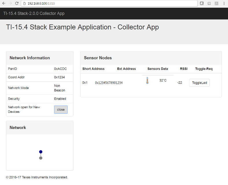
Click the Toggle LED button in the web interface
Interacting with the sensor from the gateway
Clicking the Toggle LED button sends a message to the sensor module to toggle the LED. A slight delay (up to a few seconds) my be observed before the LED is actually toggled. This delay is because the sensor nodes are normally in sleep mode, and only wake up periodically to receive commands buffered on the collector.
Final notes
Network information and state is saved in non-volatile memory by both the Collector (using the host file system) and the Sensor (using the internal Flash memory). This ensures that both devices can re-establish the connection following a power-cycle. If you want to repeat task 5 from scratch, you will need to reset both the Collector and the Sensor to their factory defaults, as explained in the lab material above (button-press combination for the Sensor, and deleting the file nv-simulation.bin for the Collector)
Want to get deeper?
This lab is based on pre-built binaries. To build run the example from the source, please refer to Linux Development Host chapter in the TI 15.4-Stack Linux Developer’s Guide.
References
15.4 Stack Documentation – Available at https://dev.ti.com/tirex/explore/node?node=ACA4JejIBOUb1EEBZyGp1gpTTHBmuLATEST
CC13xx Software Overview – Available at https://www.ti.com/tool/SIMPLELINK-CC13XX-CC26XX-SDK.
CC13xx Technical Reference Manual – Available here
This work is licensed under a Creative Commons Attribution-NonCommercial-NoDerivatives 4.0 International License.