Introduction
This module is an advanced study and walkthrough of the Over the Air Download (OAD) feature of the TI 15.4-Stack. It is assumed that the reader has a basic knowledge of embedded C tool chains and general C programming concepts. This lab is intended as additional material for users who are already familiar with the OAD concepts presented in the OAD Chapter of the TI 15.4-Stack User's Guide.
The lab will contain several tasks:
Task 1: Build and Flash the Sensor
Task 2: Build and Flash the Coprocessor
Task 3: Setup your Linux Gateway with the Coprocessor
Task 4: Join the Sensor to the Network
Task 5: Update the Sensor with OAD
Technical support
For any questions you may have, please have a look at the relevant E2E forum - TI Sub-1 GHz E2E Forum
OAD Overview
In this section, we will go over the various components involved in an OAD image from a high level.
Default Non OAD Image
We will begin with the template for a standard 15.4-stack image that does not have OAD enabled.
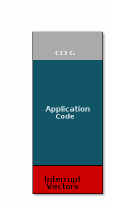
There are three main components of this image:
- The instructions/constants that implement the compiled form of the program (application code)
- The reset vectors in the ARM Cortex M format: ARM Cortex M4F Vector Table
- The CCFG, which contains chip configuration parameters, see the Technical Reference Manual
These three components are required for any image that is to run on the CC26xx or CC13xx. The goal of OAD is to get an executable image of this form on the device via an over the air update, no JTAG or wires required.
However, in order to achieve the goal of making the image pictured above upgradeable over the air, a few software components must be set in place.
Image Fragmentation/ Image Header
Even with the largest payload size supported by the IEEE 802.15.4 Specification, an entire CC26xx/CC13xx image cannot be sent in an single packet. Therefore, the image to be sent over the air must be fragmented into a size that will fit into packet payloads.
However, there is no way for the receiving device to know information about the incoming image. This problem is solved by using the OAD Image Header. The OAD Image Header contains metadata describing the image and is used by the application and BIM to determine the suitability of an image for downloading or loading. Other benefits of the OAD Image Header are:
- Image metadata is bundled as part of the image
- A running image can query knowledge about itself by reading the header
- Bootloader software can read the header to determine which image(s) are present and active
- Information about the incoming image is available to the target early in the OAD process.
Now, that we are sold on the benefits of an image header in an OAD system, here is an updated drawing of the stock image with an image header added.
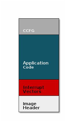
Comparison: Image with and without header
The space available to the code section of the image is shrunk to accommodate
the header, and the reset vectors are pushed back to accommodate the header.
These changes are specified in the linker script (shrinking app space) and the
RTOS .cfg file (relocating reset vectors).
Boot Image Manager (BIM)
A running image cannot update itself. This means that incoming OAD image must be stored in a temporary location while it is being received. This temporary location can be a reserved location in internal flash outside of the executable area covered in the first image. Alternatively, the temporary location can be in an external flash chip
After the download is complete, some code must determine if the new image is valid, and if current image should be overwritten, and finally execute the new image.
This piece of code is referred to as the Boot Image Manger (BIM) in the TI OAD solution.
BIM is intended to be permanently resident on the device, meaning it persists through many OADs and cannot be updated.
BIM will run every time the device boots and determine if a new image should be loaded and run (based on image header).
Furthermore, the BIM and CCFG structure are tied together, because both are required for a successful device boot.
The CCFG is needed by the boot ROM and startup firmware for device trim and to
determine where program execution is to start from. By default the boot ROM will
jump to address 0x00000000 and look for a vector table, but this region is
now occupied by the image header. A custom CCFG must be used to instruct the
device to jump directly to the BIM.
From there the BIM will perform device trim based on the CCFG settings, and determine and load the optimal image based on the OAD image header.
The BIM code will require more reserved space in our system. See below for the memory map after a BIM has been added to the last image.
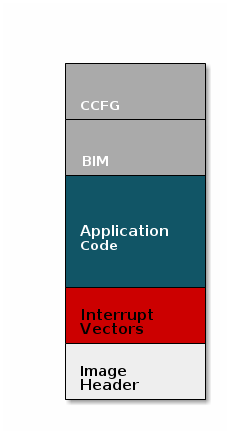
CCFG and BIM
The BIM is responsible for linking and defining the CCFG structure, instead of the application as in the non OAD case. This ensures that the device always will always execute the BIM after boot.
OAD Protocol
Currently we have covered all the necessary building blocks for updating an image local to the target device. The only missing piece is a vehicle for sending the OAD blocks over the air, and storing them on the target device.
This functionality is implemented by the TI 15.4-Stack OAD profile.
At a high level, the TI 15.4-Stack OAD profile is responsible for the following:
- Determining if the candidate image should be accepted for download
- Receiving and unpacking image blocks and storing them
- Writing the received blocks to non volatile storage
- Verifying the received image post download
The TI 15.4-Stack OAD profile is implemented in the oad_client.c file and its associated
flash wrappers.
If you want more information or more detailed dive into OAD, check out the OAD Chapter of the TI 15.4-Stack User's Guide.
Supported Devices/SDKs
This lab is intended to be used with the newest SDKs for each of these TI devices:
| TI Device | SDK |
|---|---|
| CC13xx & CC26xx | SIMPLELINK-CC13XX-CC26XX-SDK |
Prerequisites
Background
Some basic Linux knowledge is required for performing this lab. We recommend that you take a look at the TI 15.4-Stack User's Guide along with working through the Sensor and Collector SimpleLink Academy and the Linux Gateway Project Zero SimpleLink Academy before doing this module. The Sensor and Collector SLA will help you learn about how TI's 15.4-Stack works and the Linux Gateway Project Zero SLA will take you through the initial setup of a Linux Gateway Project with TI 15.4-Stack as well as introduce to you the purpose and uses of the gateway.
Software
- UniFlash
- The corresponding SDK(s) from the list above
- TI 15.4-Stack Linux Gateway SDK 2.2.0 or later (Will be set up in Task 3 below)
- PROCESSOR-SDK-LINUX-AM335X SD Card Image v. 03.02.00.05 for BeagleBone Black (Only if using Embedded host)
- (Optional) You may also use the Linux Debian image for your specific Beaglebone. Use the Stretch IoT (without graphical desktop) image.
- Tera term or any other equivalent terminal program
Hardware
- 2 x Compatible LaunchPads, refer to the Supported Devices/SDKs section
- 2 x USB Cables
- Wired network access (e.g. Wi-Fi router with an available Ethernet connection)
- Host platform - either one of:
- Embedded host platform
- BeagleBone Black rev. C (other revisions of the BBB may be compatible, but were not tested)
- Compatible 5v Power adapter
- Ethernet cable
- TTL-232R-3V3 USB to TTL Serial cable by FTDI, AKA simply as FTDI cable (optional)
- PC host platform
- A PC or a virtual machine connected to the local network and running ubuntu
- Embedded host platform
- A PC or a virtual machine running ubuntu 18.04 64bit (required, even if using an embedded host), for extracting the pre-compiled gateway binaries from the Linux SDK installer (other Linux versions may also be compatible but were not tested)
- A Windows PC for running SmartRF Flash Programmer or Uniflash and for installing the SimpleLink CC13xx/CC26xx SDK
Using a PC host may provide easier development and debugging capabilities. If you already have an available ubuntu PC or virtual machine, it will also provide a faster bring-up time, as you will not need to re-install the host environment. On the other hand, while using the BeagleBone as a host may involve some extra steps for setting it up, it provides a more realistic environment, closer to the embedded target product.
Note
This lab can be performed using any CC13xx or CC26xx LaunchPad. The training material is based on CC1352, so if using any other CC13xx device, all references to CC1352 in text and screenshots should be referred to as your particular board.
Task 0: Label your LaunchPads
Label each of your LaunchPads with its XDS Device ID, as described here.
Additionally, label one LaunchPad as "Sensor" and the other as "MAC-CoP". These labels will be referred to throughout this lab. It is recommended to use a non-permanent marking for this (e.g. sticky notes), as these labels may only be relevant for this specific lab.
Task 1: Build and Flash the Sensor
In this task, we will be importing both a Sensor OAD project and a board
specific Boot Image Manager (BIM) project. When compiled, the Sensor OAD
project will have 3 forms of output files, .out, .hex, and .bin. For the
purpose of this lab, we will only be using the .bin file. The .bin file is
the file that is generated by the OAD post build step. This is the only file
type that will work for OAD as the others will not contain header data. The
.bin file will be loaded onto the Sensor board with the BIM project. The BIM
project's purpose is as its name describes, as the board boots up, the BIM is
in charge of which image on the board to use. This task will show you how to
put an image into off chip flash for the BIM to boot from.
It is assumed you have already installed your corresponding SDK from the supported device list section. If not, please install it now.
Open CCS and import two projects from the SDK you installed:
First, import the Sensos OAD Project found at:
sdk/examples/rtos/YOURBOARD/ti154stack/sensor_oad_offchip_secureSecond, import the BIM found at:
sdk/examples/nortos/YOURBOARD/bim/bim_offchipIt should look something like this:
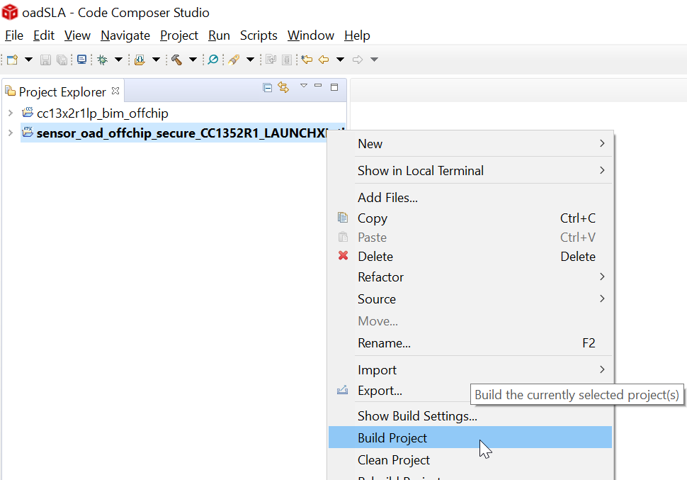
Build both projects
Connect the "Sensor" LaunchPad to the Windows PC.
Run UniFlash, and perform the following steps:
Uniflash will automatically find any LaunchPads that are connected to your PC:
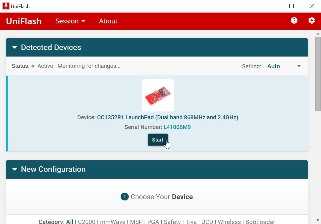
If more than one LaunchPad is connected to the pc:
Make sure to select the correct LaunchPad when programming the firmware: Compare the XDS Device ID that you written on the LaunchPad in Task 0 to the device ID shown in the serial number field of the image above.
Select the board you labeled as Sensor and in the
Select and Load Imagessection, browse and find the BIM image you just built and choose the.hexfile.Hit the
Add Another Imageoption button as shown below: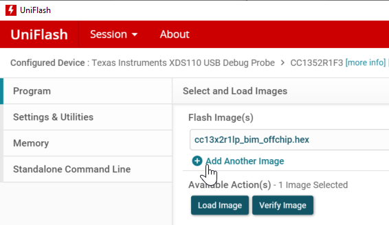
Browse and find the Sensor OAD image you just built and choose the
.binfile. Once chosen, load the images. Make sure to erase the NV to ensure no extraneous data is left on the device.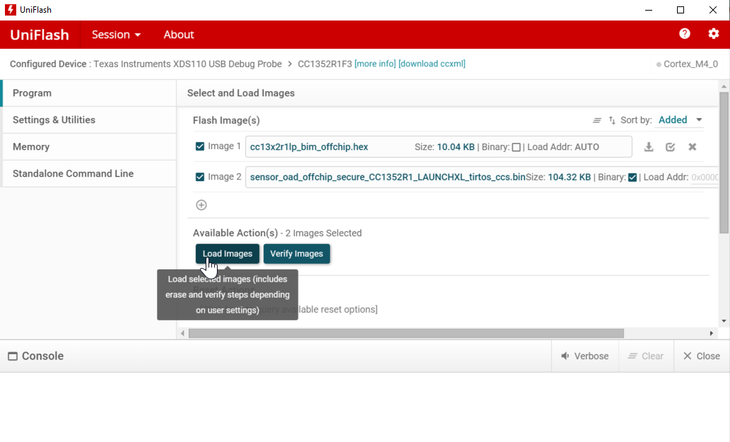
Task 2: Build and Flash the Coprocessor
This task is for building and flashing your coprocessor. Your coprocessor is the way your 15.4 network will be able to connect with a Linux Gateway.
In CCS, import and build the Coprocessor project found at:
sdk/examples/rtos/YOURBOARD/ti154stack/coprocessorConnect your Coprocessor board and load the
.heximage.
Task 3: Setup your Linux Gateway with the Coprocessor
For the purposes of this tutorial, the lab will be run using a Virtual Machine running Ubuntu. If you follow the directions of the Linux Gateway Project Zero SLA, you should be able to run this on a BeagleBone Black or Native Ubuntu PC as well.
Note
If not using a VM skip to step 2. The screenshots used in this training are using a VM as a host, but the steps will work on a native Linux machine, a dedicated BBB, or a VM.
Follow steps 3-4 from the Linux Gateway Project Zero SLA to set up your Linux Gateway SDK on your linux machine.
Once you have the SDK installed and your linux machine ready, connect the Coprocessor board to that machine.
On your VM, connect to your Coprocessor board by going to the
Devicemenu, and inUSB, select the board to connect to: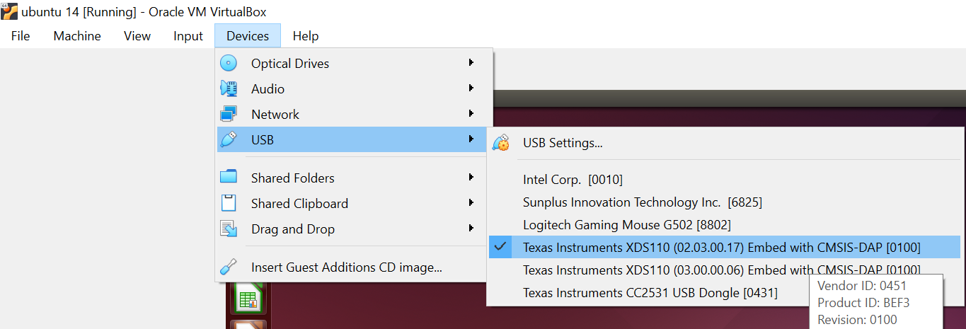
Open up a terminal (in Ubuntu, you can hit
ctrlaltt) and navigate to where you installed the linux SDK.Once inside the SDK, navigate to:
prebuilt/bin.Inside this folder, there are a few binary files along with a few configuration files. We will use these as default to run the demo. Run the command:
./host_collector collector.cfg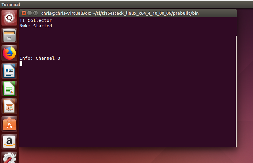
The coprocessor has a number of commands, to open the 15.4 Gateway network, in the terminal, type the command
oand press enter.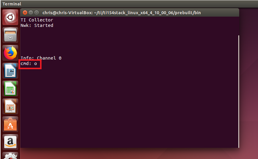
Note:
You can find a list of the available commands located in the Sensor OAD README file.
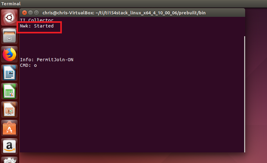
- As you can see below, the network has now started:
Task 4: Join the Sensor to the Network
This task will walk you through how to connect your Sensor OAD to the Linux Gateway Network we formed in Task 3.
Open up a Terminal and connect to your sensor board:
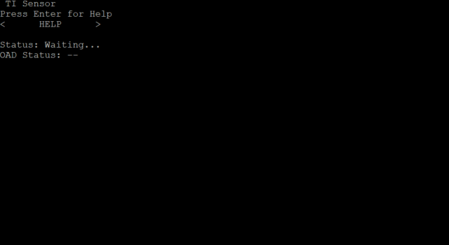
Connect your OAD Sensor by navigating to the
NETWORK ACTIONSmenu, and selectASSOCIATE: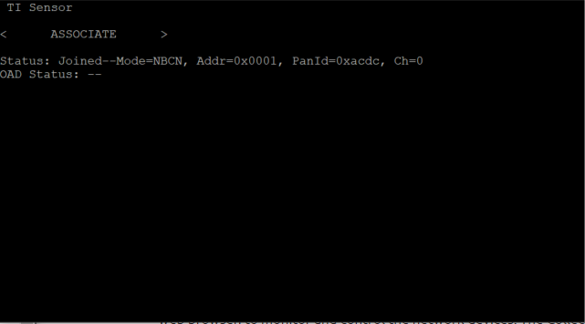
Task 5: Update the Sensor with OAD
Back in the Coprocessor terminal, select the sensor by using the command:
s 1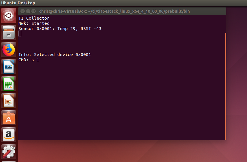
- The command
sis used to select a sensor by its short address. If your Sensor's short address is not 0x0001, then type in your short address following thesand a space (0xnot needed).
- The command
You can check the version of the sensor by using the command
v.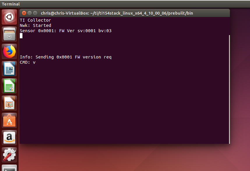
- As you can see above, the Sensor Version (sv) is 1, and the BIM version
(bv) is 3. This is good to know because we can re-run this
vversion request command after performing the OAD to verify that the software version has been updated and therefore the software update was successful.
- As you can see above, the Sensor Version (sv) is 1, and the BIM version
(bv) is 3. This is good to know because we can re-run this
The last step before performing the OAD is to create the updated software image. In the Sensor OAD CCS project, we will make a small change to show the software version is pushed through. Open up the file:
sensor/application/sensor/oad/oad_image_header_app.c.In the constants section, update the Software version:
#define SOFTWARE_VER {'0', '0', '0', '2'}Build the sensor project. Then copy the
.binfile into an easily accessible directory. For the purposes of this tutorial, we put the image into thesdk/prebuilt/bindirectory.To perform the OAD, we have to select the image from within the host collector linux application. To do this use the command
f, space and the location of the file: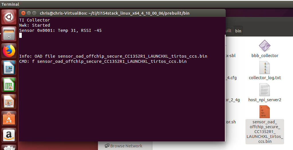
After the image is selected, perform the update by using the command
u: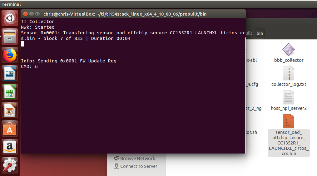
You will see the sensor receiving the image:

Once the download has finished, you have successfully completed TI 15.4-Stack
OAD! You can check by re-running the v command.
Optional Task: Enable Turbo OAD
Turbo OAD is OAD that only sends the delta of the different images to the sensor. This will dramatically decrease the amount of time it takes for the OAD process to complete. The first image made for the sensor must be Turbo OAD enabled.
To enable Turbo OAD, open the
sensor.syscfgfile in CCS and in theTI 15.4 Stackmodule, open theOADsubmodule, and inside theTurbo OADdrop down, you can enable it by selecting the check box for the option:Enable Turbo OAD.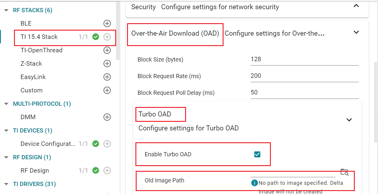
Go through Tasks 1-4 above.
Once you have reached Task 5, make sure you set the path to the old version 1 image in the
sensor.syscfgfile.Finally, when using theLinux Gateway Terminal to select the second image to flash, make sure to select the
.dimfile rather than the.bin.Finish out the remainder of Task 5 and you will have completed the Turbo OAD process!
References
15.4 Stack Documentation – Available at https://dev.ti.com/tirex/explore/node?node=ACA4JejIBOUb1EEBZyGp1gpTTHBmuLATEST
CC13xx Software Overview – Available at https://www.ti.com/tool/SIMPLELINK-CC13XX-CC26XX-SDK.
CC13xx Technical Reference Manual – Available here
This work is licensed under a Creative Commons Attribution-NonCommercial-NoDerivatives 4.0 International License.