Introduction
This SimpleLink Academy lab introduces the reader to the fundamentals of DMM, and it is recommended to use this lab as a starting point for any DMM implementation done on a CC13xx or CC26xx device.
The Dynamic Multi-protocol Manager (DMM) allows multiple wireless stacks to coexist and operate concurrently on a single radio on a CC13xx or CC26xx device. DMM allows the user to define and control the priorities and timing constraints of each stack at run-time.
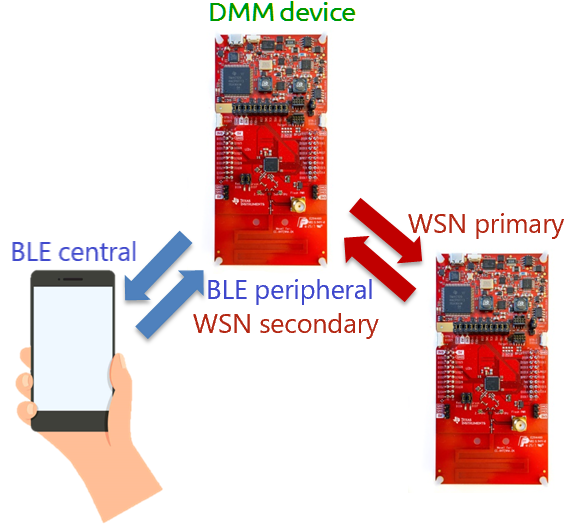
This lab will show how to use a single device as an EasyLink Wireless Sensor Network (WSN) Node on a sub-1 GHz radio frequency (RF) network while simultaneously acting as a BLE peripheral.
It is assumed that the user has previous knowledge of the Bluetooth® Low Energy (BLE) protocol and the EasyLink WSN Node and Concentrator topology. You can learn about this in the BLE and Proprietary RF SimpleLink Academy labs.
Additional examples
This lab focuses on explaining the fundamentals of using DMM, which is why the DMM example with BLE Peripheral and EasyLink is used. DMM is not limited to this combination. There are other DMM examples in the SimpleLink CC13xx / CC26xx SDK with different wireless stack combinations, such as a TI 15.4 Sensor or ZigBee End Device with a BLE Peripheral.
For more information on available combinations and limitations, please refer to the DMM User's Guide.
Prerequisites
Other SimpleLink Academy Labs
- Completion of BLE Fundamentals
- Completion of BLE Connections
- Completion of Proprietary RF Wireless Sensor Network example
Hardware
For the DMM device, 1x LaunchPad of either:
- SimpleLink CC1352R1 LaunchPad,
- SimpleLink CC1352P LaunchPad,
- SimpleLink CC1352P7 LaunchPad,
- SimpleLink CC1352R LaunchPad SensorTag Kit, or
- Any other Sub-1 GHz & BLE DMM-capable LaunchPad variant
For the WSN Concentrator device, 1x Sub-1 GHz LaunchPad
A smartphone with a BLE explorer app
Note
Depending on which LaunchPad is used as the DMM device, the antenna will be tuned for different frequency bands. This is also reflected in the EasyLink examples for the LaunchPad in question.
For the WSN Node to be able to communicate with the collector, the two devices must have compatible settings. If using the same LaunchPad version for both the WSN Node and WSN Collector, the examples will have matching settings per default.
Software
- Code Composer Studio (latest version) with support for CC13xx/CC26xx devices
- SimpleLink CC13xx / CC26xx SDK (latest version)
- If the WSN Concentrator device is a CC1310 or CC1350, then
- SimpleLink CC13x0 SDK (latest version)
Recommended reading
It is recommended to read the DMM User's Guide, BLE5-Stack User's Guide, and Proprietary RF User's Guide alongside this lab for details and further information.
Before you start
Attention
The steps in this lab make reference to the CC1352R1 LaunchPad. Please note that the same steps apply when using either boards listed under required hardware.
Install the SimpleLink CC13xx/CC26xx SDK.
Install Code Composer Studio (CCS). These instructions assume that you install CCS with support for the CC13xx and CC26xx devices.
Setup CCS Workspace
Before we start, create an empty CCS workspace and import the following example projects:
dmm_wsnnode_remote_display_app, found under<SDK>/examples/rtos/<BOARD>/dmm/.rfWsnConcentrator, found under<SDK>/examples/rtos/<BOARD>/easylink/.
where <SDK> is the install location of the SimpleLink SDK, and <BOARD> must
correspond to the board being used for that example project.
To import an example from the SimpleLink SDK, follow these steps within your workspace in Code Composer Studio:
Select
Project→Import CCS Projects...to open the import dialog.Browse to the path of the example as the search directory. Click
Select Folder.Select the example project, and click
Finishto import the example application.Repeat the process for the other example project.
Project README
You can refer to the project's README file for a functional description of each example.
Group Training – Additional Requirements
If you are working in groups, make sure to always use your designated frequency to avoid interfering with other operations. Also, change the BLE scan response to output a uniquely identifiable name.
Feel free to skip this section if you are not participating in a group training.
Frequency Allocation
In order to avoid interfering with other groups when operating on the same frequency, use a unique frequency during this lab.
Ask your Instructor
If you are part of a group training, please ask the instructor for a base frequency and a unique number to generate your unique frequency to use during this lab.
For simplicity, it is possible to select a base frequency (915.0 MHz, 868.0
MHz, 433.0 MHz), allocate a running number to each of the operators and
have each operator multiply their number with a 100 kHz channel spacing. For
example with using base frequency 868.0 MHz, group #5 would use the
following frequency 868 + 0.1 * 5 = 868.5 MHz.
The frequency is configured in both examples with SysConfig as such:
Open SysConfig by double clicking on the
*.syscfgfile.dmm_wsnnode_remote_display.syscfgfordmm_wsnnode_remote_display_app.rfWsnConcentrator.syscfgforrfWsnConcentrator.
In SysConfig, navigate to
EasyLink→Radio→Custom Radio Settings→PHY Properties→Frequency (MHz).Change the value of
Frequency (MHz)to the unique frequency.
Note
If using a CC1310 or CC1350 LaunchPad as the WSN Concentrator device,
the frequency is not configurable using SysConfig. Instead the
ConcentratorRadioTask.c file need to be modified where the following
lines of code need to be uncommented and updated to match the expected
frequency:
    /* If you wish to use a frequency other than the default use
     * the below API */
     EasyLink_setFrequency(868000000);
BLE Scan Response
To make it easier for the operators to distinguish between the BLE advertisements, it is recommended to change the BLE scan response to output a unique identifiable name.
Ask your Instructor
If you are part of a group training, please ask the instructor for a unique number to use in your scan response during this lab.
The BLE scan response is configured in dmm_wsnnode_remote_display_app with
SysConfig as such:
Open SysConfig by double clicking on the
dmm_wsnnode_remote_display.syscfgfile.In SysConfig, navigate to
BLE→Broadcaster Configuration→Advertisement Set 1→Scan Response Data 1→Complete Local Name.Change the value of
Complete Local Nameto the unique identifiable name.
Dynamic Multi-protocol Manager (DMM)
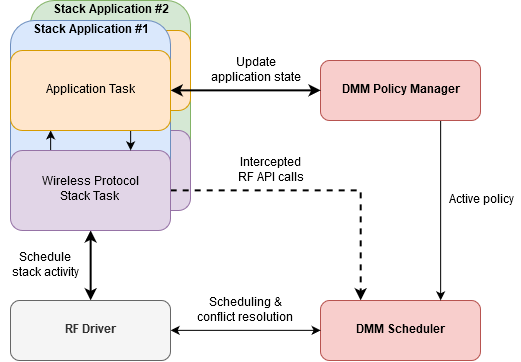
DMM is a layer between the RF protocol stacks and the RF Driver. It provides hooks to the RF driver, replacing the default scheduling behavior. It will modify the order in which RF commands are scheduled based on constraints and requirements from the applications and stacks. For a full description of DMM, please refer to the DMM User's Guide.
DMM consists of two modules:
- The DMM Policy Manager – determines the current DMM policy from the DMM policy table, based on the current combination of stack states and stack activities as reported by the applications and protocol stacks, respectively.
- The DMM Scheduler – manages the scheduling and conflict resolution of the queued RF commands.
A block diagram of DMM in relation to the stack applications and the RF driver is given in the following figure:
DMM is configured in SysConfig under the Multi-Protocol section. Below is an overview of that configuration page.
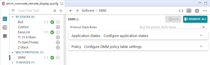
Protocol stack roles are unique IDs assigned to each stack application, and is used to identify which stack application is updating its application state to DMM. Each stack application has a set of one or more application states, and is configurable by the developer.
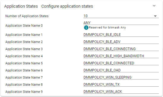
In the case of the dmm_wsnnode_remote_display_app example, a set of
application states has already been defined for both the BLE and WSN
application. Note the special application state ANY, which is used to match
any application state when making a DMM policy.
The current application state of both stack applications results in an active DMM policy from the DMM policy table. A DMM policy is the scheduling rule for both stack applications and the DMM policy table makes up the complete set these scheduling rules used in the system. This is explained in more detail later.
Quiz
How does DMM know what application state the BLE peripheral application is in?
DMM Policy Manager
The primary goal of the DMM policy manager is to determine which stack application has priority over the other at any given time. This is used by the DMM scheduler when a protocol stack schedules an RF command which creates a conflict with a different protocol stack.
In order to determine which stack application has priority over the other, the DMM policy manager keeps track of the current DMM policy, combined with scheduled RF activities. A DMM policy decides the scheduling rules for both protocol stacks, and in the end determines which protocol stack has priority over the other. The complete set of all DMM policies used in the system are stored in the DMM policy table.
DMM Policy Table Order
The order of policy table entries matter, since the search of the active DMM policy is done in ascending order and will return on the first match.
Priorities are set by the Global Priority Table (GPT). GPT defines the base priority for all stack activities. It is this base priority, combined with the weight from the active DMM Policy, that determines which stack has priority over the other for a given stack activity.
GPT is not configured in SysConfig. TI provides pre-made GPTs in the SDK,
found under <SDK>/source/ti/dmm/. These GPTs are named
dmm_priority_{stacks}.h/c, and serves as a starting point with tested default
values. Please refer to the source code for more documentation and overview of
each GPT.
Priority Tiebreaker
The GPT and DMM policy table should be designed to avoid ties; how else are you supposed to decide who has priority?
In the unlikely event of a tie, the last DMM policy entry in the policy table, also known as the default policy, acts as a tiebreaker. The stack with the higher priority in that policy wins.
A DMM policy tells the scheduler which stack has priority in a certain application state and whether submitted RF commands can be deferred or not. From the policy, the scheduler can deduce how a scheduling conflict shall be resolved. Each policy within the structure represents a comprehensive system state for each stack application and consists of the following parameters:
- Weight – an application weight where a higher value represents a higher priority
- Paused Stack – callback notification if the stack application must pause or resume the radio activity
- Application States – one or more application states for which this policy is valid for
- Applied Activity – none or more stack activities for which this policy applies to
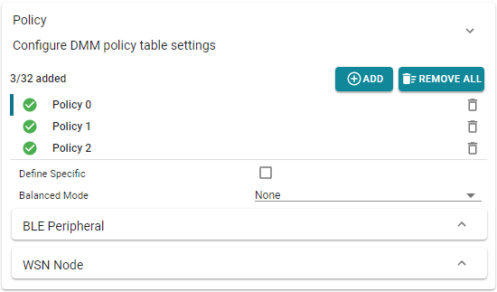
Below is a DMM policy from the dmm_wsnnode_remote_display_app, which
configures the following:
- BLE Peripheral application
- must be in the BLE OAD application state; where
- weight is not applied to any stack activity; and
- no pause requirements
- WSN Node application
- can be in Any application state; where
- weight is not applied to any stack activity; and
- radio activity must be paused
This DMM policy could be described in words as such: when the BLE application is in some OAD operation, regardless of what radio activity, and the WSN Node is in whatever state and radio activity, they both have equal weight, but the WSN Node application must pause its radio activity.
This example is not OAD enabled
While it exists policies hinting about OAD capabilities, this example is actually not OAD enabled. For OAD enabled versions of the DMM examples, use the examples with "oad" in the name.
In SysConfig, the same DMM policy would be configured as such:
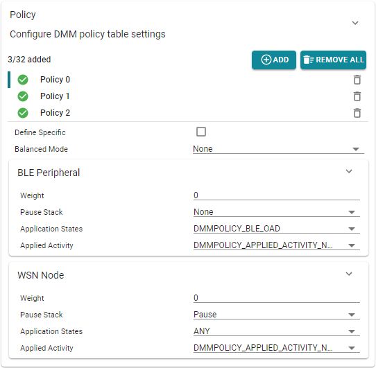
Balanced Mode
Looking closer at the policy table, one will notice the "Balanced Mode" dropdown option. To learn more about this feature and how it impacts the DMM scheduling behavior, please see the DMM User's Guide.
Applications use the DMMPolicy_updateStackState() API to notify DMM of an
application state change, which takes a protocol stack role and the new
application state as arguments. Calling this functions multiple times in a row
with the same arguments will not change the active DMM policy, it will only
cause unnecessary overhead and is generally recommended to avoid.
Quiz
Study the DMM policy table in SysConfig. Which of the following statements are true?
DMM Scheduler
As illustrated in the DMM block diagram, the DMM Scheduler handles some of the interactions with the RF driver while most of them are routed to the RF Driver without any modification. A core concept of DMM is that the wireless protocol stack does not need to be directly aware that DMM is present. In other words, it should be able to operate as normal no matter if it is running in a DMM context or not.
In order for DMM to inject itself in-between the wireless protocol stacks and the RF driver without directly changing the RF driver API calls, some RF Driver API functions are re-mapped to the equivalent DMM function. In both the BLE Peripheral and WSN Node stack, the DMM RF map header file is included instead of the RF driver when DMM is used.
#ifndef USE_DMM
#include <ti/drivers/rf/RF.h>
#else
#include <dmm/dmm_rfmap.h>
#endif //USE_DMM
rd_ble_user_config.c – the RF driver remapping to DMM is included instead of the RF driver when USE_DMM is defined
Note that the define USE_DMM is used as a feature flag to differentiate
between a DMM and non-DMM application. If you take a look at the file
dmm/dmm_rfmap.h you can see which RF driver functions are redefined.
RF Driver Concepts
To fully understand the DMM scheduler you need to understand how the RF driver operates with RF commands and the internal RF command queue. This can be read in more detail in the Proprietary RF User's Guide.
When a wireless protocol stack submits an RF command, the RF driver will invoke the scheduler function supplied by the DMM to schedule the command. The DMM Scheduler acts according to the following criteria:
- What are the current stack priorities?
- What are the timing constraints of the scheduled RF command?
- Are there any commands in the RF queue, and what priority do they have?
At first, the DMM scheduler will try to simply schedule the new command directly based on its start time. If the DMM scheduler is not able to schedule the command due to a conflict with another stack, it will try to resolve the conflict using the current stack priority and timing constraints.
When it is time to run the next command in the RF command queue, the RF driver will invoke the DMM execution function to get a decision on how to process the next command. The DMM Scheduler will act according to the active policy just like it did during scheduling, resolving any potential conflict that might exist between the (potentially) running command and the next one.
Quiz
Which of the following statements is the expected behavior for the DMM Scheduler?
Task 1 – Setup the DMM Device
The first task is to setup the DMM example application on the DMM device.
Build the DMM example (
dmm_wsnnode_remote_display_app) by doing one of the following:Right clicking on the project in the project explorer and selecting
Build
Project
Clicking
Project→Build ProjectClicking the hammer icon
Ctrl + B
Debug the DMM example by doing one of the following:
Right clicking on the project in the project explorer and selecting
Debug As→Code Composer Studio Debug SessionClicking
Run→DebugClicking the green bug icon
F11
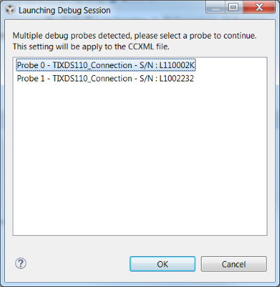
If you have multiple debug probes are connected to your computer, CCS will prompt you to select one. This serial number will be set as the debug connection for this target configuration.
Once the debug session has flashed the device, the debugging session should halt a
main(). Allow the example application to free run by:Clicking
Run→ResumeClicking the green resume button
F8
End the debugging session by clicking the red stop button.
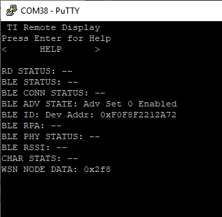
Connect a terminal program to see the serial output from the device. This is described in the BLE Fundamentals SimpleLink Academy lab. When you press play, the device will output the following:
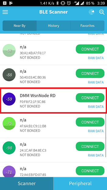
Verify the device is advertising over BLE with a smartphone. Steps for connecting to a smartphone are given in the BLE Fundamentals SimpleLink Academy lab.
The device will either advertise with the default name "DMM WSNNode RD" as seen below, or using the name chosen following the group training recommendations.
DMM Device is now setup
You now have a device that is concurrently running as a WSN Node and as a BLE Peripheral.
Task 2 – Setup the WSN Concentrator
The DMM device is a WSN Node. We need a WSN Concentrator to connect to it in order to see the Sub-1 GHz network. Setting up a WSN Concentrator is described in the SimpleLink Academy module Proprietary RF Wireless Sensor Network Example.
When you start the WSN Concentrator, the node will connect to it automatically. You may have noticed that the WSN Node outputs a counter, called "WSN Node Data". You can now see that this information is transmitted to the concentrator.
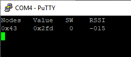
We now have two devices connected to the DMM device over two different RF protocols. With your phone, you can use the Remote Display Service to interact with the WSN network.
Interacting with the node and concentrator over BLE
While connected to the WSN Node over BLE it is possible to interact with
both the WSN Node and WSN Concentrator (via the WSN Node). Information on
how to interact with the WSN network is found inside the
dmm_wsnnode_remote_display_app README.
Limitations
Unlike Task scheduling in TI-RTOS, RF scheduling cannot be preempted and resumed at a later time. Instead, DMM will use the policy table to resolve scheduling conflicts between the stacks. Whenever there is a scheduling conflict, DMM will either reject the new command or abort the conflicting command in favor of the new command. This means that there are limitations to which DMM use-cases that are feasible.
When looking at the Global Priority Table, we can see that the BLE stack in the "normal" priority case is always assigned a lower weight then that of the EasyLink stack. This remains true for most weights when comparing the two stacks on a priority bases. The only cases where the BLE stack is assigned a higher weight when comparing priority levels is in the "high connection establishment" and "urgent connection" case.
/* Global Priority Table: BLE connection lower than WSN data */
StackActivity activityBLE_bleLwsnH[ACTIVITY_NUM_BLE*PRIORITY_NUM] =
{

    DMM_GLOBAL_PRIORITY(DMM_BLE_CONNECTION, DMM_StackPNormal, 80),
    DMM_GLOBAL_PRIORITY(DMM_BLE_CONNECTION, DMM_StackPHigh, 170),
    DMM_GLOBAL_PRIORITY(DMM_BLE_CONNECTION, DMM_StackPUrgent, 250),

    DMM_GLOBAL_PRIORITY(DMM_BLE_CON_EST, DMM_StackPNormal, 80),
    DMM_GLOBAL_PRIORITY(DMM_BLE_CON_EST, DMM_StackPHigh, 200),
    DMM_GLOBAL_PRIORITY(DMM_BLE_CON_EST, DMM_StackPUrgent, 220),

    DMM_GLOBAL_PRIORITY(DMM_BLE_BROADCASTING, DMM_StackPNormal, 70),
    DMM_GLOBAL_PRIORITY(DMM_BLE_BROADCASTING, DMM_StackPHigh, 7),
    DMM_GLOBAL_PRIORITY(DMM_BLE_BROADCASTING, DMM_StackPUrgent, 210),

    DMM_GLOBAL_PRIORITY(DMM_BLE_OBSERVING, DMM_StackPNormal, 70),
    DMM_GLOBAL_PRIORITY(DMM_BLE_OBSERVING, DMM_StackPHigh, 160),
    DMM_GLOBAL_PRIORITY(DMM_BLE_OBSERVING, DMM_StackPUrgent, 210),
};

StackActivity activityWSN_bleLwsnH[ACTIVITY_NUM_WSN*PRIORITY_NUM] =
{

    DMM_GLOBAL_PRIORITY(DMM_WSN_RETRANSMIT, DMM_StackPNormal, 90),
    DMM_GLOBAL_PRIORITY(DMM_WSN_RETRANSMIT, DMM_StackPHigh, 180),
    DMM_GLOBAL_PRIORITY(DMM_WSN_RETRANSMIT, DMM_StackPUrgent, 240),

    DMM_GLOBAL_PRIORITY(DMM_WSN_TRANSMIT, DMM_StackPNormal, 90),
    DMM_GLOBAL_PRIORITY(DMM_WSN_TRANSMIT, DMM_StackPHigh, 180),
    DMM_GLOBAL_PRIORITY(DMM_WSN_TRANSMIT, DMM_StackPUrgent, 240),

    DMM_GLOBAL_PRIORITY(DMM_WSN_RECEIVE, DMM_StackPNormal, 90),
    DMM_GLOBAL_PRIORITY(DMM_WSN_RECEIVE, DMM_StackPHigh, 180),
    DMM_GLOBAL_PRIORITY(DMM_WSN_RECEIVE, DMM_StackPUrgent, 240),
};
dmm_priority_ble_wsn.c – Default Global Priority Table for the dmm_wsnnode_remote_display_app example
In this example, the BLE Peripheral is set to advertise at a 100ms interval while the WSN Node is set to transmit a packet every second. This means that for most of the time there will be no scheduling conflicts, and if one was to arise the WSN Node would have higher priority. In theory, assuming ideal conditions, the WSN Concentrator would never miss a WSN Node packet while the BLE Peripheral is in advertising mode.
Connecting to the BLE Peripheral will for a moment change the application state which will result in a momentary increase in weight in addition to the GPT, making the WSN Node low priority. Once the connection is established the application state will again change back to one where the WSN Node has priority.
As the BLE peripheral connects to the central, the BLE activity could increase depending on the negotiated interval. You can read about the connection interval negotiation in the BLE connection lab. This means that when connecting to the BLE Peripheral, we are more likely to get a conflict where the BLE stack is denied radio access.
BLE connection interval
The BLE peripheral has no control over the final connection interval as it is controlled by the BLE central.
The BLE peripheral being denied radio access is typically not an issue as it will always retry the transmission during the next connection interval. As long as the BLE peripheral is able to respond to one such event during the negotiated supervision timeout, the connection will remain active. If the BLE peripheral is denied radio access too many times and risks losing the connection to the central, the BLE stack would update the stack GPT priority. It would start by raising the priority to "high" and if that is not enough, "urgent".
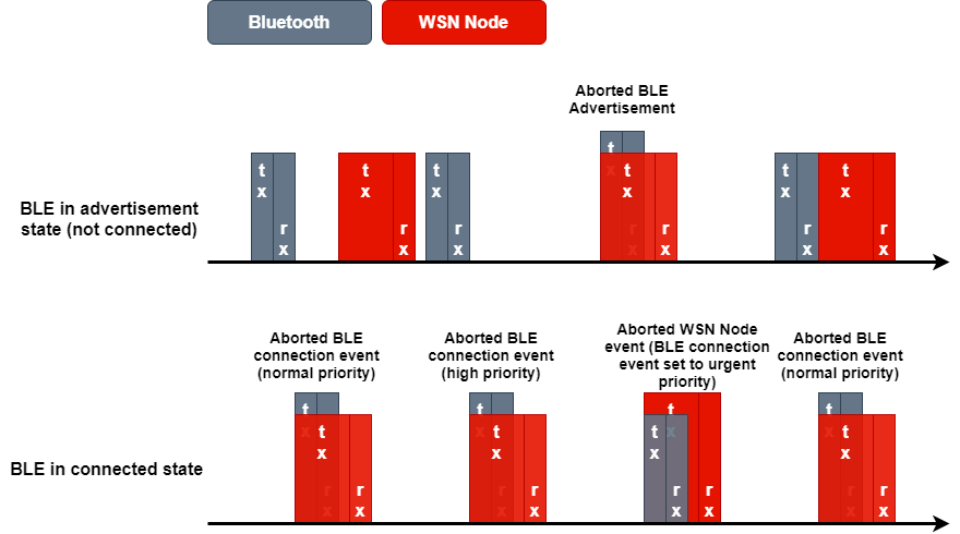
As noted earlier, an "urgent connection" in the scope of the GPT has the heaviest weight and as a result, this command would always succeed to run. This allows the BLE stack to keep the connection alive, even if it is considered the lowest priority stack in the system. This is the strength of the GPT, allowing the user to consider special case scenarios in the stack without having to implement application logic to handle these using the application policy table.
This is illustrated in the packet diagram below where the aborted packets are in the background of the higher priority one. The diagram provide an example of what one could expect to happen depending on the state of the BLE stack, being in an active connection or not.
Quiz
Which of the following aspects are important in the context of DMM when considering running two stack applications?
Task 3 – Enable Statistics
Let us setup our DMM project to observe some WSN Node statistics! The WSN Node application already keeps track of some statistics, but we need to enable the printouts of these statistics. We do this by doing the following:
Navigate to
Project Properties→Build→ARM Compiler→Predefined Symbols.Add the define
RD_DISPLAY_WSN_STATS.Build project and flash the DMM device.
While already tracking some statistics, the WSN Node does not track the number of aborted commands per default. We will need to modify the WSN Node application to also count the numbers of aborted packages.
Inside NodeRadioTask.c, found under application/wsn_node/, navigate to the
rxDoneCallback() function and add another check to handle aborted commands.
/* did the Rx timeout */
else if(status == EasyLink_Status_Rx_Timeout)
{
    /* Post a RADIO_EVENT_ACK_TIMEOUT event */
    Event_post(radioOperationEventHandle, RADIO_EVENT_ACK_TIMEOUT);

    radioStats.ackRxTimeout++;
    RemoteDisplay_updateNodeWsnStats(&radioStats);
}
// =========== ADD START ===========
else if (status == EasyLink_Status_Aborted)
{
    /* Count number of aborted packages */
    radioStats.ackRxAbort++;
    Event_post(radioOperationEventHandle, RADIO_EVENT_ACK_TIMEOUT);
}
// =========== ADD END ===========
else
{
    /* The Ack reception may have been corrupted causing an error.
     * Treat this as a timeout
     */
    Event_post(radioOperationEventHandle, RADIO_EVENT_ACK_TIMEOUT);
    rxErrorFlg |= status;
    radioStats.ackRxSchError++;
    RemoteDisplay_updateNodeWsnStats(&radioStats);
}
NodeRadioTask.c – rxDoneCallback()
Abort Status for EasyLink
EasyLink_Status_Aborted is the EasyLink stack return status received
when the RF driver reports a command as stopped or aborted. The WSN Node
application is built on top of the EasyLink stack.
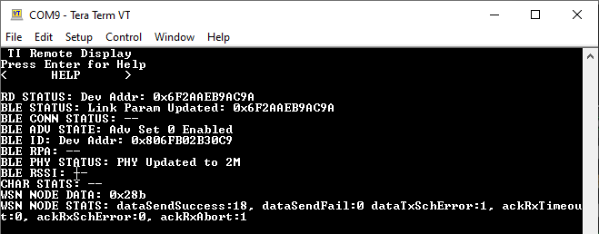
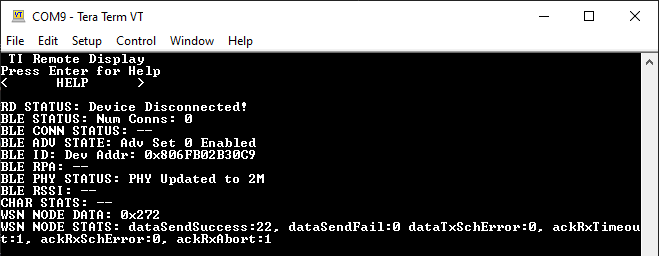
Build and download the changed project to the DMM device. When pressing play, the terminal output from the device should look something like this:
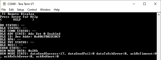
Ideally, you should not see the WSN Node missing any packages. Based on how our DMM policy table is setup, we would expect the WSN Node to be of highest priority (almost) all of the time.
Messing With The Priorities
Now, let us see what happens if we alter the GPT to instead favor BLE in
all scenarios except "urgent" EasyLink packages. We do this by modifying the
dmm_priority_ble_wsn.c file found under dmm/ in the imported project.
/* Global Priority Table: BLE connection lower than WSN data */
StackActivity activityBLE_bleLwsnH[ACTIVITY_NUM_BLE*PRIORITY_NUM] =
{

    DMM_GLOBAL_PRIORITY(DMM_BLE_CONNECTION, DMM_StackPNormal, 100),
    DMM_GLOBAL_PRIORITY(DMM_BLE_CONNECTION, DMM_StackPHigh, 100),
    DMM_GLOBAL_PRIORITY(DMM_BLE_CONNECTION, DMM_StackPUrgent, 100),

    DMM_GLOBAL_PRIORITY(DMM_BLE_CON_EST, DMM_StackPNormal, 100),
    DMM_GLOBAL_PRIORITY(DMM_BLE_CON_EST, DMM_StackPHigh, 100),
    DMM_GLOBAL_PRIORITY(DMM_BLE_CON_EST, DMM_StackPUrgent, 100),

    DMM_GLOBAL_PRIORITY(DMM_BLE_BROADCASTING, DMM_StackPNormal, 100),
    DMM_GLOBAL_PRIORITY(DMM_BLE_BROADCASTING, DMM_StackPHigh, 100),
    DMM_GLOBAL_PRIORITY(DMM_BLE_BROADCASTING, DMM_StackPUrgent, 100),

    DMM_GLOBAL_PRIORITY(DMM_BLE_OBSERVING, DMM_StackPNormal, 100),
    DMM_GLOBAL_PRIORITY(DMM_BLE_OBSERVING, DMM_StackPHigh, 100),
    DMM_GLOBAL_PRIORITY(DMM_BLE_OBSERVING, DMM_StackPUrgent, 100),
};

StackActivity activityWSN_bleLwsnH[ACTIVITY_NUM_WSN*PRIORITY_NUM] =
{

    DMM_GLOBAL_PRIORITY(DMM_WSN_RETRANSMIT, DMM_StackPNormal, 50),
    DMM_GLOBAL_PRIORITY(DMM_WSN_RETRANSMIT, DMM_StackPHigh, 50),
    DMM_GLOBAL_PRIORITY(DMM_WSN_RETRANSMIT, DMM_StackPUrgent, 240),

    DMM_GLOBAL_PRIORITY(DMM_WSN_TRANSMIT, DMM_StackPNormal, 50),
    DMM_GLOBAL_PRIORITY(DMM_WSN_TRANSMIT, DMM_StackPHigh, 50),
    DMM_GLOBAL_PRIORITY(DMM_WSN_TRANSMIT, DMM_StackPUrgent, 240),

    DMM_GLOBAL_PRIORITY(DMM_WSN_RECEIVE, DMM_StackPNormal, 50),
    DMM_GLOBAL_PRIORITY(DMM_WSN_RECEIVE, DMM_StackPHigh, 50),
    DMM_GLOBAL_PRIORITY(DMM_WSN_RECEIVE, DMM_StackPUrgent, 240),
};
dmm_priority_ble_wsn.c – Modified Global Priority Table(s)
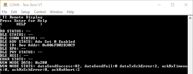
Looking at the modification above, we would expect the BLE stack to have higher priority in all cases where the EasyLink application is not using "urgent" priorities. Build and download the changed project to the DMM device and study the connection statistics of the WSN Node once more.
The picture above show the new "worst case" scenario where the BLE stack is in a connected state and the communication is more frequent. We can see that the WSN Node has experienced a few aborted commands as well as a few scheduling errors. This indicates that there has been conflicts between the two stacks where the BLE side was favored, just as we expect.
We can however still see that there was no "failed" transmissions between the WSN Node and the WSN Collector. This is because no matter if the WSN Node missed an ACK from the WSN Concentrator due to an interrupted RX, or that the WSN Node was not able to schedule an RX or TX command, it was able to send the package at a later time. Furthermore, the EasyLink application does not schedule transmissions at an absolute time which allows the DMM to postpone already scheduled commands to a later time in case of a conflict.
When missing an ACK from the collector, the WSN Node will try to re-transmit the
packet a specific number of times before it is counted as a dataSendFail.
The number of retries the WSN node will perform is defined by
NODERADIO_MAX_RETRIES inside NodeRadioTask.c. Only if
all of these retries fails, the WSN Node will increase the dataSentFail
statistic.
Messing With The Timings
Now, let us see what happens if we change the WSN Node timings in such a way
that the ACK RX window is sure to interfere with the BLE stack commands.
Inside NodeRadioTask.c, the WSN Node RX timeout noRadioAckTimeoutTimeMs is
set at the beginning of the nodeRadioTaskFunction() function.
noRadioAckTimeoutTimeMs sets the RX timeout the WSN Node uses when listening
for a ACK from the WSN Concentrator.
Change the defined NODERADIO_ACK_TIMEOUT_MS value which is used as the default
value from 160ms to 10000ms. This means that the RX command for sure will
overlap with the BLE stack packages and likely also the supervision timeout of a
connected BLE device.
#define NODERADIO_ACK_TIMEOUT_MS (10000) // (160)
NodeRadioTask.c
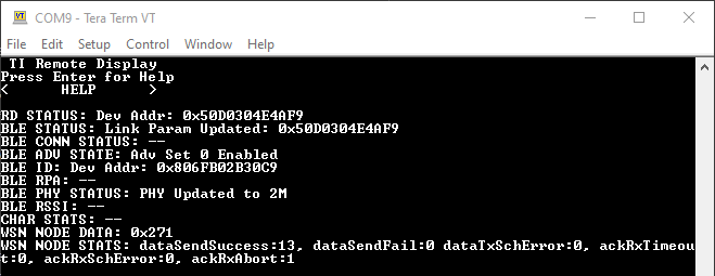
Build, download and run the changed project to the DMM device to observe how the statistics change.
Looking at the statistics, it is clear that this change did not change much. This is expected as the EasyLink application is lower in priority and the WSN Concentrator is still active which means it will respond to the ACKs as expected. As the collector side issues the ACK, the WSN Node RX timeout will never trigger and thus have a much smaller risk of interfering with the BLE stack side.
Now, disconnect your WSN Concentrator device to force the WSN Node to
experience RX timeouts. We expect to see that the DMM device is unable to send
any data messages to the WSN Concentrator, and the dataSendFail and
ackRxAbort count is increasing.
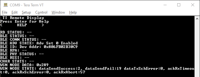
As expected, the statistics shows that the WSN Node now actually is getting aborted most of the time as it tries to stay in RX for a long period of time while being assigned a lower priority. When connecting to the device over BLE, it remains clear that the increased RX timeout did not impact the BLE connection performance, just as expected.
On the other hand, our previous modifications to the GPT was setup to bump "urgent" priority WSN Node commands to the highest priority. Why do we not see this happening as the numbers of aborted commands increase? The answer is that the WSN Node only raises the EasyLink priority if a command is rejected during scheduling and not if it is aborted.
This is the intended behavior but lets see what happens if we choose to also
increase the EasyLink priority when the RX is aborted. To do this, we modify the
application to raise the priority to "urgent" if there is an aborted RX as well
as makings sure it does not reset back to "normal". We start by again modifying
the WSN Node rxDoneCallback found in the NodeRadioTask.c file:
    else if (status == EasyLink_Status_Aborted)
    {
        /* Increase priority to urgent */
        txCmdPriEsc.cmdPriority = EasyLink_Priority_Urgent;

        /* Count number of aborted packages */
        radioStats.ackRxAbort++;
        Event_post(radioOperationEventHandle, RADIO_EVENT_ACK_TIMEOUT);
    }
rxDoneCallback() – Modified WSN Node RX callback
We then disable the "default to normal" option in the application by modifying
the updateCmdPriority function in the same file:
  static void updateCmdPriority(cmdPriorityEscalation_t* pCmdPriEsc, bool isCmdRejected)
  {
      if(isCmdRejected == true)
      {
          /* update total cmd-rejected count */
          pCmdPriEsc->nTotalRejected++;
          /* command was rejected */
          if(++(pCmdPriEsc->nCmdRejected) == pCmdPriEsc->nRejectBeforEscalation)
          {
              pCmdPriEsc->nCmdRejected = 0U;
              if(pCmdPriEsc->cmdPriority != EasyLink_Priority_Urgent)
              {
                  /* Bump the priority, unless already at urgent, when N_REJECT_TO_ESCALATE_PRIORITY
                  * commands are successively rejected
                  */
                  (pCmdPriEsc->cmdPriority)++;
              }
          }
      }
      else // isCmdRejected == false
      {
          /* Command was successful, reset count and return priority to normal */
          pCmdPriEsc->nCmdRejected = 0U;
          // ========== EDIT START ==============
          // pCmdPriEsc->cmdPriority  = EasyLink_Priority_Normal;
          // =========== EDIT END ===============
      }
  }
updateCmdPriority() – Modified priority update API
Build, download and run the changed project to the DMM device to observe how the statistics change. We now expect that as soon as the WSN Node is aborted, the priorities would flip in favor of the WSN Node.
Don't forget the WSN Collector
Do not forget to again connect the WSN Collector before running the freshly modified project as this would cause an immediate "abort" situation on the WSN Node with the long RX timeout used.
From start, we will see the device behaving as expected and we are able to connect with the BLE Peripheral and read out values.
Now, disconnect the WSN Concentrator to "force" the WSN Node to stay in RX for the full timeout period.
As the WSN Concentrator is disconnected, we see that our BLE device loses the connection and stops advertising. This is exactly what we expect to happen as the WSN Node is now staying in RX for a long time (10s). This happens as the EasyLink stack, after the previous modifications to the application, will raise the priority to "urgent" following the first aborted command.
Due to the long RX period of the WSN Node, the BLE stack would be unable to show up for the connection event time slot negotiated with the BLE central. If the BLE stack do not mange to show up before the supervision timeout expires, the connection is dropped.
Feeling adventurous?
Try playing with the Global Priority Table to see how this would further impact the current modified project. What happens if you set the BLE stacks "urgent" priority values to be higher than those of the EasyLink stack?
Congratulations!
You have successfully reached the end of the DMM Fundamentals lab.
To learn even more about how to leverage the DMM and the SDK examples,
see the other DMM trainings.
DMM Customizing Use Case – Shows how to modify an existing
example to fit another use-case
DMM Integration – Shows how to create a DMM BLE project from
scratch and how to integrate a proprietary stack along side it.
This work is licensed under a Creative Commons Attribution-NonCommercial-NoDerivatives 4.0 International License.