Introduction
The 2Mbps and Coded Radio Physical Layer was added to the Bluetooth Core Spec in version 5. You can increase throughput by increasing data rate from legacy 1 Mbps to 2 Mbps or you can increase range by using coded PHY.
In this module we will learn about the Bluetooth® low energy (BLE) physical layers (PHY), how to configure and switch PHY. The different benefits are listed in the table below. Note that by reducing the data rate, the average power consumption might increase because it takes more time to transmit and receive data causing longer intervals in active TX and RX states.
| PHY | Data Rate | Theoretical Relative Range | Advantage |
|---|---|---|---|
| 2 Mbps | 2 Mb/s | ~0.8x | Speed (Throughput) |
| 1 Mbps | 1 Mb/s | 1x | Compatilbility (balanced) |
| Coded S2 | 500 kbps | 2x | Range |
| Coded S8 | 125 kbps | 4x | Range x2 |
BLE 5 PHY Collateral
Please consider the presentation called What is Bluetooth 5 and When do I Use it? to quickly learn about the BLE 5 PHYs and features.
In this lab we will be working with the example project Project Zero and BTool in order to form a BLE connection and issue a PHY change request. This SimpleLink Academy lab uses projects from the BLE5-Stack, which can be found in the SimpleLink™ CC13XX / CC26XX software development kit (SDK).
This tutorial will take about two hours to complete and requires basic embedded programming skills (see the Prerequisites section for details).
In the first task, BTool will be used to initiate a connection and send a Read Current PHY command (
HCI_LE_ReadPhy) from the central device using BTool.In the second task, we will try to send a change PHY request from the central device using BTool.
In the third task, we will try to send a change PHY request from the peripheral device instead.
In the fourth task, we are going to show what happens when a change PHY request is sent to a device that does not support LE 2M PHY.
In the first bonus task, we will use the LE Coded PHY.
In the second bonus task, the LE 2M PHY will be used for advertisements.
Attention
This lab cannot be run from CCS Cloud. In order to do this lab, you need to install the relevant SimpleLink™ software development kit locally.
Prerequisites
Hardware
For this lab, you need two Bluetooth-enabled development boards. Supported devices are:
- SimpleLink™ CC26x2R LaunchPad™
- SimpleLink™ CC2652RSIP LaunchPad™
- SimpleLink™ CC2652RB LaunchPad™
- SimpleLink™ CC1352R LaunchPad™
- SimpleLink™ CC1352P LaunchPad™
- SimpleLink™ CC2652R7 LaunchPad™
- SimpleLink™ CC1352P7 LaunchPad™
- SimpleLink™ CC2651P3 LaunchPad™
Other SimpleLink Academy Labs
- Completion of BLE Scanning and Advertising
- Completion of BLE Connections
Software
- CCS 12.1 or IAR 8.50.9 installed with support for CC13xx/CC26xx devices.
- SimpleLink™ CC13XX and CC26XX SDK 6.30
- BTool (located in the
tools\ble5stackdirectory of the SimpleLink™ SDK installation)
Setup
To start with this training module, two LaunchPads will be programmed with
- Project Zero to act as a peripheral device
- Host Test to act as a central device.
Both example projects can be found in the examples folder in the SDK.
About the LE PHYs
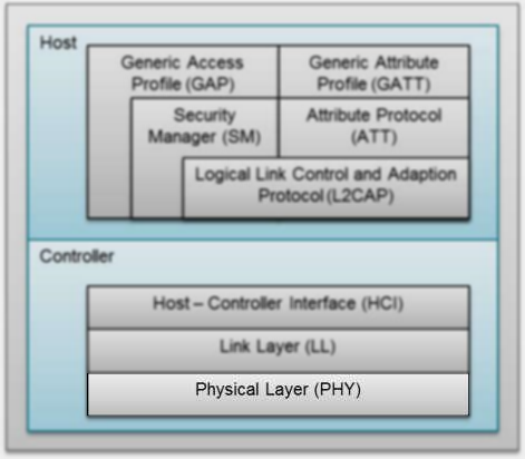
The physical layer (PHY) is the lowest layer of the Bluetooth® low energy protocol stack. It configures the physical parameters of the radio transmission and reception. It determines how a bit (and its value) are represented over the air.
A full guide of the physical layer is given in the [TI BLE5-Stack User's Guide], see the PHY section located in BLE5-Stack → Physical Layer (PHY).
One of the key parameters of a physical layer is the symbol rate. The symbol rate represents how many symbols are sent/received per second. For 1M PHY one symbol represents one bit. When we switch from the 1 Mbps physical layer to the 2 Mbps physical layer, the symbol rate is doubled. This means that data is transmitted at twice the speed. The LE Coded PHY feature uses the same transmit power as the LE 1M PHY and the same symbol rate (1Mbps), the only change is in the modulation of data in the PHY where the bits are coded and is represented by either two symbols (LE Coded S=2, data rate 500kbps) or eight symbols (LE Coded S=8, data rate 125kbps). Using the LE Coded PHY, the energy consumption increases because the radio is in Tx longer.
The channel width is the same for all LE PHYs in order for them to coexist. When changing from LE 1M PHY to LE 2M PHY, the bandwidth goes up. However, the channel spacing in BLE is high enough (2 MHz) that this does not cause a problem.
The main advantage of the 2 Mbps physical layer over the 1 Mbps physical layer is that the transmission speed is increased. This means that the radio spends less time transmitting/receiving data. This will reduce the device energy consumption for sending the same amount of data. The main application for LE Coded PHY should be applications that need longer range (with the penalty of lower data rate).
A comparison of the physical layers is given in the following table.
| Parameter | Comparison |
|---|---|
| Power consumption | For the same transmit power, the energy consumption is reduced when using LE 2M PHY and increased when using CODED PHY. |
| Data rate | The LE 2M PHY is two times faster to transmit data than the LE 1M PHY, but actual application data throughput is lower due to overhead and protocol timing requirements. CODED PHY has lower data rate. |
| Receive sensitivity | The link budget will be lower in the LE 2M PHY relative to the LE 1M PHY, due to the increased symbol rate and the link budget will be higher for CODED PHY which can provide longer range. |
| Transmit power | The output power is same for all PHYs. |
Quiz
Which of the following use-cases would benefit from using the LE 2M PHY?
Which of the following use-cases would benefit from using the LE Coded PHY?
Bluetooth 5 PHY Possibilities and Restrictions
In the SLA module BLE Scanning and Advertising, we learned that it is possible to advertise on all the Bluetooth low energy PHYs:
- LE 1M PHY
- LE 2M PHY
- LE Coded PHY
According to the Bluetooth Core Spec v5.0, only AUX_ADV_IND, AUX_SYNC_IND and
AUX_CHAIN_IND can be sent on the LE 2M PHY. All these packets have to be
preceded by an ADV_EXT_IND packet sent on the LE 1M PHY. The ADV_EXT_IND
packets contain pointers to the extended advertising packet sent on the
secondary PHY.
By using this method, a lot more advertising data can be sent when compared to Bluetooth 4.2 advertising (legacy advertising). (254 bytes per packets vs. 31 bytes per packet.) The drawback is that the overhead is increased; you have to transmit multiple packets, and the auxiliary advertisement packets contain the extended advertising header in addition to the advertisement data.
Note that there is no way of transmitting an advertisement packet on the LE 2M
PHY without first transmitting an ADV_EXT_IND packet on the LE 1M PHY.
In this SimpleLink Academy module we will change the PHY inside a connection. In Bonus Task 2 we will advertise on the LE 2M PHY.
PHY Change in a Bluetooth Connection
Since the key parameters of the radio changes when we change the PHY of a connection, it is crucial that both devices in the connection agree on the PHY change. This is handled in the BLE5-Stack with a PHY change request.
The set PHY command is defined in the Bluetooth Core Spec as HCI_LE_Set_PHY.
- You can read about the
HCI_LE_Set_PHYcommand in the Bluetooth 5 Core Spec, Vol 2, Part E, section 7.8.49 LE Set PHY Command.
In the Bluetooth Core Spec, all the HCI_LE_Set_PHY command parameters are
described. You can also see what events are generated by this command.
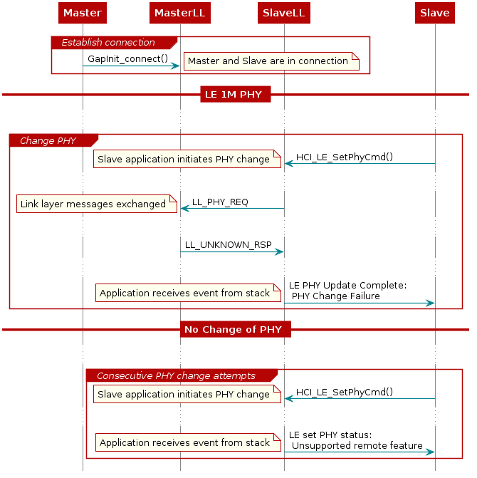
An HCI command is a command sent from the Host to the Controller. In this case,
the application sends the command to the Link Layer. In the following figure you can see the HCI_LE_SetPhyCmd, and the
following LL_PHY_REQ and LL_PHY_RSP exchange over the air.
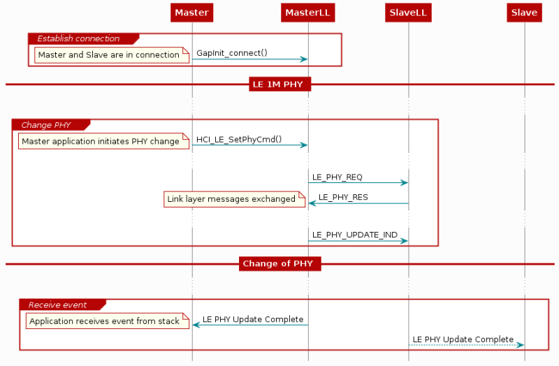
Both the central and the peripheral device are given the chance to refuse the PHY
change. In the LL_PHY_REQ and LL_PHY_RSP, each device indicates which PHYs
they prefer to use. The PHY will not be updated unless both devices have named
the PHY as a preferred PHY.
Task 1 – Initiate a Connection and Read the Current PHY
Program one LaunchPad with Project Zero, and one with Host Test from BLE5-Stack. (If you don't remember how to do this, a description is given in BLE Connections.) Open a UART logging window for Project Zero.
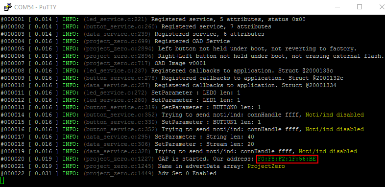
Open BTool by using the Run-BTool.bat file which is located in
<SDK_INSTALL_DIR>\tools\ble5stack\btool. In order to connect with Project
Zero from BTool, we need the peripheral's device address BDA. The peripheral's device address can be found in the UART log as shown
below:
In BTool, press the Scan button. BTool will start printing out
GAP_AdvertiserScannerEvent logs. Connect to Project Zero by using its BDA.
Now, that a link is established, we are going to try to figure out which PHY is
currently used in this connection. The command we will use is HCI_LE_ReadPhy,
which can be found under Advanced Commands in BTool.
- You can read more about the
HCI_LE_ReadPhycommand in the Bluetooth Core Specification, Vol 2, Part E, 7.8.47 LE Read PHY Command.
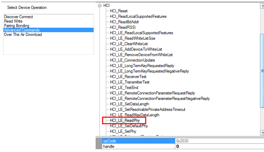
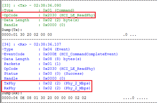
The HCI_LE_ReadPhy command is used to read the current transmitter PHY and
receiver PHY on the connection identified by the (connection) handle.
Once the HCI_LE_ReadPhy command is issued, the device which issued the command
will generate an HCI_CommandCompleteEvent. The return event contains the following fields:
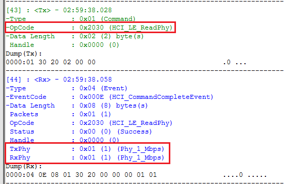
As you can see, the default PHY used to establish the connection is the LE 1M PHY. The table shows how to interpret different return values for the TxPhy and RxPhy fields.
| Value | Definition |
|---|---|
| 1 | The transmitter/receiver PHY for the connection is LE 1M PHY. |
| 2 | The transmitter/receiver PHY for the connection is LE 2M PHY. |
| 3 | The transmitter/receiver PHY for the connection is LE Coded PHY. |
Task 2 – Send 'Change PHY Request' using BTool
As described in the PHY section of the [TI BLE5-Stack User's Guide] (located in BLE5-Stack → Physical Layer (PHY)), BLE5 projects in the SimpleLink SDK will by default support both the LE 1M PHY and the LE 2M PHY.
To change the PHY used in a connection, we can use the HCI_LE_SetPhy command,
which can be found under Adv. Commands in BTool.
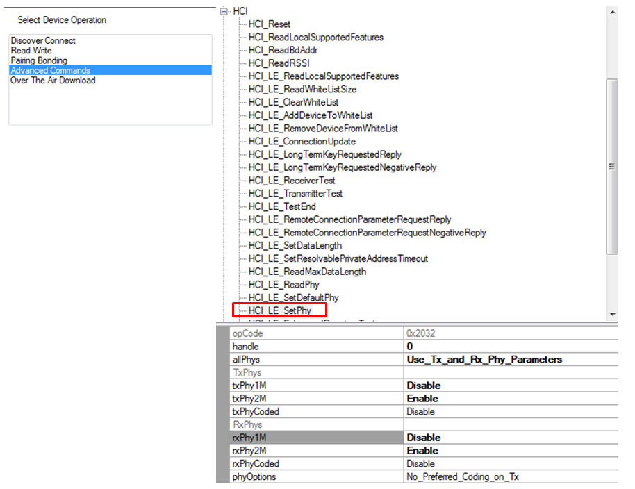
In order to use this command, we need to understand all the parameter fields.
- The parameters of
HCI_LE_SetPhyare listed in the Bluetooth Core Specification, Vol 2, Part E, section 7.8.49 LE Set PHY Command.
The following lists all the parameters for HCI_LE_SetPhy and explains the
parameters.
Parameters for HCI_LE_SetPhy
handle
This is the connection handle. For more information regarding how to identify the current connection handle, please take a look at the SimpleLink Academy training module BLE Connections.
allPhys
The host preference on how to handle txPhy and rxPhy. There are four options for the allPhys field:
| Option | Definition |
|---|---|
| Use_Tx_and_Rx_Phy_Parameter | The final preferred PHY setting will be taken from the txPhy and rxPhy fields |
| Any_Tx_Phy_Use_Rx_Phy_Parameter | The final preferred PHY setting will be taken from the rxPhy field |
| Use_Tx_Phy_Parameter_Any_Rx_Phy | The final preferred PHY setting will be taken from the txPhy field |
| Any_Tx_or_Rx_Phy | The sender does not have a preferred PHY. The txPhy/rxPhy fields will be ignored. The current PHY will be updated to the fastest PHY both devices support. |
txPhy & rxPhy
Bit field of Host preferred Tx and Rx PHYs. The definition of the txPhy and rxPhy fields are shown below. In Btool, these bit fields can be toggled by selecting Enable or Disable for each txPhy and rxPhy option:
| Bit Number | Value | Definition |
|---|---|---|
| 0 | 1 | The host prefers to use LE 1M PHY as Tx/Rx PHY. |
| 1 | 2 | The host prefers to use LE 2M PHY as Tx/Rx PHY. |
| 2 | 4 | The host prefers to use LE Coded PHY as Tx/Rx PHY. |
The TI BLE5-Stack does not support asymmetric connections, i.e. connections where different PHYs are used for Rx and Tx.
phyOptions
Bit field of the Host's preferred Coded PHY options. We are not going to discuss
the LE Coded PHY in this training, we will just use No_Preferred_Coding_on_Tx
for this setting.
Changing PHY
Choose parameters to change to LE 2M PHY. (If you're unsure of what to choose, look at the printout from BTool below.) Send the command. When the command is sent, BTool will output the following:
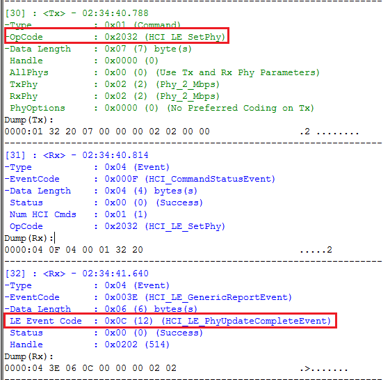
To verify that we actually changed the PHY, we can use HCI_LE_ReadPhy.
Quiz
What will happen if we set 3 (LE 1M PHY | LE 2M PHY) instead of 2
(LE 2M PHY) for both the txPhy and rxPhy fields in the HCI_LE_SetPhy command?
Important
When changing the active PHY, the preferred PHY of the PHY change initiating device will also be changed automatically. This means that in some cases, only the device that first changed the active PHY to LE 2M PHY can change it back to LE 1M PHY. The device that initiated the PHY change to LE 2M will still be able to change the PHY back to LE 1M.
Because of this, it is a good idea to change the PHY to 0x03(LE 1M PHY | LE 2M
PHY) when the application has finished all LE 2M critical operations. This will
allow the peer device to change the PHY back to LE 1M.
Task 3 – Change PHY from Project Zero
So far we have learned how to change the PHY using BTool. Now we are moving on to
changing PHY from Project Zero by a button press. We will use a button press
callback function where the HCI_LE_SetPhyCmd() is sent.
1. Send HCI_LE_SetPhyCmd()
We will be using HCI_LE_SetPhyCmd() in the Project Zero code. The
parameters of this function are the same as when using the command in BTool,
however their values are slightly different.
- Please see
hci.hfor the API description ofHCI_LE_SetPhyCmd()(you can find it in the Include folder of the app project).
hciStatus_t HCI_LE_SetPhyCmd( uint16  connHandle,
                              uint8   allPhys,
                              uint8   txPhy,
                              uint8   rxPhy,
                              uint16  phyOpts );
hci.h – Definition of HCI_LE_SetPhyCmd().
Use the API reference to choose the correct parameters for HCI_LE_SetPhyCmd().
Project Zero keeps track of connected devices in the connList variable.
// Per-handle connection info
static pzConnRec_t connList[MAX_NUM_BLE_CONNS];
project_zero.c – The connection list variable is declared in the LOCAL VARIABLES section of the code.
When a device connects to Project Zero, it's added to the connList. We can
read the connection handle from this list.
// Connected device information
typedef struct
{
    uint16_t connHandle;                    // Connection Handle
    Clock_Struct* pUpdateClock;             // pointer to clock struct
    bool phyCngRq;                          // Set to true if PHY change request is in progress
    uint8_t currPhy;                        // The active PHY for a connection
    uint8_t rqPhy;                          // The requested PHY for a connection
    uint8_t phyRqFailCnt;                   // PHY change request fail count
} pzConnRec_t;
project_zero.c – Typedef for pzConnRec_t.
Since we want the PHY to change with a button press, we need to locate the
function ProjectZero_handleButtonPress() in project_zero.c. This is the
callback function where button presses are handled.
/*********************************************************************
 * @fn      ProjectZero_handleButtonPress
 *
 * @brief   Handle a debounced button press or release in Task context.
 *          Invoked by the taskFxn based on a message received from a callback.
 *
 * @see     buttonDebounceSwiFxn
 * @see     buttonCallbackFxn
 *
 * @param   pState  pointer to pzButtonState_t message sent from debounce Swi.
 *
 * @return  None.
 */
static void ProjectZero_handleButtonPress(pzButtonState_t *pState)
{
    Log_info2("%s %s",
              (uintptr_t)(pState->gpioId ==
                          CONFIG_GPIO_BTN1 ? "Button 0" : "Button 1"),
              (uintptr_t)(pState->state ?
                          ANSI_COLOR(FG_GREEN)"pressed"ANSI_COLOR(ATTR_RESET) :
                          ANSI_COLOR(FG_YELLOW)"released"ANSI_COLOR(ATTR_RESET)
                         ));

    // Update the service with the new value.
    // Will automatically send notification/indication if enabled.
    switch(pState->gpioId)
    {
    case CONFIG_GPIO_BTN1:
        ButtonService_SetParameter(BS_BUTTON0_ID,
                                   sizeof(pState->state),
                                   &pState->state);
        break;
    case CONFIG_GPIO_BTN2:
        ButtonService_SetParameter(BS_BUTTON1_ID,
                                   sizeof(pState->state),
                                   &pState->state);
        break;
    }
}
project_zero.c :: ProjectZero_handleButtonPress() – Project Zero button press handle function.
By default, ProjectZero_handleButtonPress() outputs button presses over UART
(Log_info2()) and updates the button service when a button is pressed or released
(ButtonService_SetParameter()). We want it to update the PHY only when a
button is pressed, not when it is released. When the button is pressed, the
state member of the pState is 1. Thus, we should check this variable before
sending an HCI_LE_SetPhyCmd().
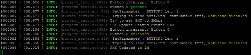
Write your code so that when Button 0 is pressed, the PHY is changed to LE 2M PHY, and when Button 1 is pressed, the PHY is changed to LE 1M PHY.
Once the HCI_LE_SetPhyCmd() is sent, the controller will post a
hciEvt_BLEPhyUpdateComplete_t event.
If the HCI_LE_SetPhyCmd() is executed successfully, HCI_LE_SetPhyCmd() will
return status = SUCCESS. Then you can check the currently used Tx/Rx PHY.
Program Project Zero, connect it to BTool, and use the Button 0 to change the PHY to LE 2M PHY.
Task 4 – Send a PHY Change Request to a Device that Does Not Support BLE 5
Connect Project Zero to a phone/central device that does not support BLE 5, for example your phone (your phone might support BLE5.x). You have to terminate the connection with BTool in order to do this. Press Button 0 to request a PHY change to LE 2M PHY. Please note that recently released phones do have BLE 5 support. Do a quick internet search of your phone model's BLE support to check if you can use your phone for this task.
Quiz
If the central device doesn't support LE 2M PHY, what happens after sending the
HCI_LE_SetPhyCmd() command?
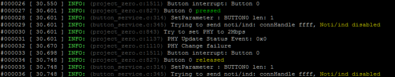
As you can see from the Project Zero log, the PHY update failed. When the phone
(the central in this connection) receives the LL_PHY_REQ packet, it does not
recognize it since it does not support Bluetooth 5. The phone responds with a
LL_UNKNOWN_RSP packet. This is illustrated in the following flow chart.
The first time Project Zero attempts changing the PHY and the phone replies with
LL_UNKNOWN_RSP, the Link Layer notes that the phone does not support PHY
change. The next time you try to change to LE 2M PHY, HCI will notify the
Project Zero application that this feature is not supported directly. This time,
no packets are sent over the air.
If you want to see how the PHY change failures are handled, check out
ProjectZero_processHCIMsg() in project_zero.c.
Bonus Task 1 – Change to Coded PHY
We can use HCI_LE_SetPhyCmd() to change the connection PHY to a LE Coded PHY.
These PHYs increase the range of the BLE connection.
If you want to know more about the LE Coded PHYs and how to increase the range, please see How does Bluetooth® 5 increase the achievable range of a Bluetooth low energy connection?
You can also read more about LE Coded PHY in the [TI BLE5-Stack User's Guide], located in BLE5-Stack → Physical Layer (PHY) → LE Coded PHY.
You can use the HCI_LE_SetPhy command to change to the LE Coded PHY. The
bit-mask value for LE Coded PHY is 0x04. You can use either BTool or Project
Zero to change to LE Coded PHY.
Supported PHYs
As previously mentioned, if multiple PHYs are supported the PHY with the highest data throughput will be chosen by the controller. Thus, if there are multiple supported PHYs, the LE Coded PHY will not be chosen.
When changing to the LE Coded PHY, you can choose whether you prefer the S=2
coding or the S=8 coding in the phyOptions parameter. You can read about the
coding options in the [TI BLE5-Stack User's Guide] located in BLE5-Stack →
Physical Layer (PHY) → LE Coded PHY.
Bonus Task 2 – Advertise on LE 2M PHY
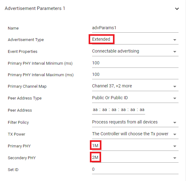
As previously stated, it is possible to use auxiliary advertisement packets to transmit advertisement data on LE 2M PHY. In order to do this, configure the advertisement set parameters in SysConfig as follows:
In this task the extended advertisement is connectable only and therefore if you call 'GapAdv_loadByHandle' with argument GAP_ADV_DATA_TYPE_SCAN_RSP the function will return bleInternalError (0x1E). To work around this, you must remove either the GapAdv_loadByHandle call or the APP_ASSERT, or both as shown below:
/*
// Comment out loading of scan response packet.
//status = GapAdv_loadByHandle(advHandleLegacy, GAP_ADV_DATA_TYPE_SCAN_RSP,
//                             sizeof(scanResData1),scanResData1);
//APP_ASSERT(status == SUCCESS);
*/
project_zero.c :: ProjectZero_processGapMessage() :: GAP_DEVICE_INIT_DONE_EVENT
Extended Advertising Scan Response Payload
Loading scan response data is only allowed for scannable advertising setting ('GAP_ADV_PROP_SCANNABLE').
// Parameters for 2M connectable advertising
#define GAPADV_PARAMS_2M_CONN {                       \
  .eventProps = GAP_ADV_PROP_CONNECTABLE,             \
  .primIntMin = 160,                                  \
  .primIntMax = 160,                                  \
  .primChanMap = GAP_ADV_CHAN_ALL,                    \
  .peerAddrType = PEER_ADDRTYPE_PUBLIC_OR_PUBLIC_ID,  \
  .peerAddr = { 0xaa, 0xaa, 0xaa, 0xaa, 0xaa, 0xaa }, \
  .filterPolicy = GAP_ADV_WL_POLICY_ANY_REQ,          \
  .txPower = GAP_ADV_TX_POWER_NO_PREFERENCE,          \
  .primPhy = GAP_ADV_PRIM_PHY_1_MBPS,                 \
  .secPhy = GAP_ADV_SEC_PHY_2_MBPS,                   \
  .sid = 0                                            \
}

GapAdv_params_t advParam2M = GAPADV_PARAMS_2M_CONN;

// Create Advertisement set and assign handle
status = GapAdv_create(&ProjectZero_advCallback, &advParam2M, &advHandleLegacy);
APP_ASSERT(status == SUCCESS);

/*
// Comment out loading of scan response packet.
//status = GapAdv_loadByHandle(advHandleLegacy, GAP_ADV_DATA_TYPE_SCAN_RSP,
//                             sizeof(scanResData1),scanResData1);
//APP_ASSERT(status == SUCCESS);
*/
project_zero.c :: ProjectZero_processGapMessage() :: GAP_DEVICE_INIT_DONE_EVENT – Configure 2M advertising.
Note the following:
- The
eventPropsparameter does not contain the legacy advertising flag,GAP_ADV_PROP_LEGACY - Also, advertising on LE 2M PHY can be either connectable or
scannable. In this case it is only connectable (
GAP_ADV_PROP_CONNECTABLE). - The primary PHY (
primPhy) is the LE 1M PHY. This is the PHY on which we will transmit theADV_EXT_INDpackets that contain the pointer to theAUX_ADV_INDpacket. - The secondary PHY (
secPhy) is, of course, the LE 2M PHY.
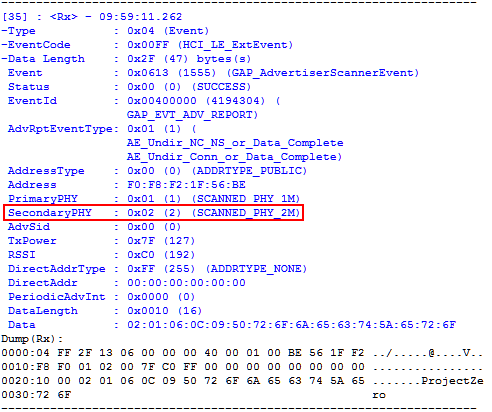
You can use BTool to scan for advertisements. The printed
GAP_AdvertiserScannerEvent will have the LE 2M PHY as the secondary PHY.
If you want, you can increase the size of the advertisement data.
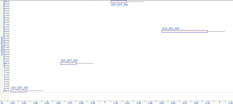
The following image shows sniffer log capture of the advertisement event. In
this case the advertisement data is 79 bytes. You can see the ADV_EXT_IND on
channel 37, 38 and 39, followed by the AUX_ADV_IND on channel 24.
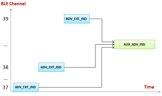
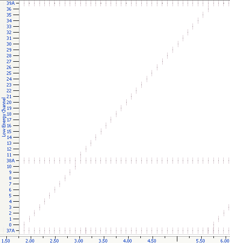
The next image is an overview of the advertisement mode. Here you can see the
three horizontal rows of ADV_EXT_IND packets. These packets are always on
channel 37, 38 and 39. On the other hand, the AUX_ADV_IND packets switch
channel for each advertisement event. All secondary advertisement channels are
used. This is the diagonal line of advertisement packets.
References
[TI BLE5-Stack User's Guide]: PHY section located at BLE5-Stack → Physical Layer (PHY)
How does Bluetooth® 5 increase the achievable range of a Bluetooth low energy connection?