Introduction
This SimpleLink Academy lab will introduce you to a different DMM example as well as focus on a new use case and how to extend what is already available in the DMM example into your own use case. This SimpleLink Academy lab serves as a continuation of the DMM Fundamentals lab.
The Dynamic Multi-protocol Manager (DMM) allows multiple wireless stacks to coexist and operate concurrently on a single radio on a CC13xx or CC26xx device. DMM allows the user to define and control the priorities and timing constraints of each stack at run-time.
This lab will use a single device as a TI 15.4 Sensor on a Sub-1 GHz network while simultaneously acting as a Bluetooth® LE (BLE) peripheral. It is thus assumed that the user has previous knowledge of the Bluetooth LE protocol and the TI 15.4 Sensor/Collector topology. You can learn about this in the Bluetooth LE and TI 15.4 Stack SimpleLink Academy labs described below in the Prerequisites section.
To run this demo, you will also need a TI 15.4 collector and a Bluetooth LE central. We will use a smart phone as the BLE central, however you can use any BLE central. For the TI 15.4 Collector, you can use a second device such as CC1352R, CC1352P, CC1350 or CC1310. Since these devices are interchangeable, this device will just be referenced as the TI 15.4 Collector in the following text. Throughout the lab, the CC1352R1 LaunchPad will be used and referenced to as the DMM device or LaunchPad.
Prerequisites
Other SimpleLink Academy Labs
- Completion of DMM Fundamentals
- Completion of BLE Fundamentals
- Completion of BLE Connections
- Completion of Custom Profile
- Completion of 15.4 Stack Sensor and Collector
Hardware
For the DMM device, 1x LaunchPad of either:
- SimpleLink CC1352R1 LaunchPad,
- SimpleLink CC1352P LaunchPad,
- SimpleLink CC1352P7 LaunchPad,
- SimpleLink CC1352R LaunchPad SensorTag Kit, or
- Any other Sub-1 GHz & BLE DMM-capable LaunchPad variant
For the TI 15.4 Collector device, 1x Sub-1 GHz LaunchPad
A smart phone with a Bluetooth LE explorer app
Software
- Code Composer Studio (latest version) with support for CC13xx/CC26xx devices
- SimpleLink CC13xx / CC26xx SDK (latest version)
- If the TI 15.4 Collector device is a CC1310 or CC1350, then
- SimpleLink CC13x0 SDK (latest version)
Recommended reading
It is recommended to read the DMM User's Guide, BLE5-Stack User's Guide, and 15.4-Stack User's Guide alongside this lab for details and further information.
Group Training – Additional Requirements
If you are working in groups, make sure to always use your designated frequency band and channel to avoid interfering with other operations. Also, change the BLE scan response to output a uniquely identifiable name.
Only for group training
Feel free to skip this section if you are not participating in a group training.
Frequency Allocation
In order to avoid interfering with other groups when operating on the same frequency band, use a unique channel during this lab.
Ask your Instructor
If you are part of a group training, please ask the instructor for a specific channel or unique PAN ID to use during this lab.
For simplicity, it is possible to select a base frequency (915.0 MHz, 868.0
MHz, 433.0 MHz), and update the channel mask as explained below:
Updating the channel mask
- The stack can be configured to enable any of the supported channels. If more
than one channel is enabled, the best ("most quiet") channel is selected by the
collector when starting the network. When the sensor looks for a network to join,
it scans all the enabled channels until it finds the collector.
- To enabled the required channel and disable the other channels, you will need
to edit the channel mask definition. This configuration item is a bitmask
representing all the available channels, this is represented as a drop down menu
and you can select the channels you want transmit on by checking the box.
- Each student should update the definition of this configuration item such that
only its designated channel is enabled, and all other channels are disabled. For
example, student #10 should have it defined as
Channel 9. - Note that the number of supported channels may be limited, depending on the frequency band being used. Please make sure to select a channel within the supported range - see the note box below.
Available channels
- The number of supported channels depend on the selected frequency band:
- 915 MHz band - channels 0 to 128 - total of 129 channels
- 868 MHz band - channels 0 to 33 - total of 34 channels
- 433 MHz band - channels 0 to 6 - total of 7 channels
Multiple ways to prevent conflicts
In this lab, each student uses a different channel, in order to avoid conflicts. Using TI 15.4-Stack, there is another way to avoid conflicts, which allows using the same channels by everybody. This method involves pre-assigning the same PAN-ID to every device in the intended network, and different PAN-IDs to different networks. The stack will automatically filter and accept only the packets targeted for its PAN. The downside of this would be that in a large classroom with many setups this could lead to channel congestion and a high rate of dropped packets.
More info
For more information regarding the available configuration settings, please see the TI 15.4-Stack User's Guide.
The frequency band, PAN ID, and channel mask are configured in both examples with SysConfig as such:
Open SysConfig by double clicking on the
*.syscfgfile.dmm_154sensor_remote_display.syscfgfordmm_154sensor_remote_display_app.collector.syscfgforcollector.
In SysConfig, navigate to
TI 15.4 Stack→Radioand change the value ofSub-1 GHz Frequencyto the desired frequency band.In SysConfig, navigate to
TI 15.4 Stack→Networkand change the value ofPan IDandChannel Maskto their unique values.
Bluetooth LE Scan Response
To make it easier for the operators to distinguish between the Bluetooth LE advertisements, it is recommended to change the Bluetooth LE scan response to output a unique identifiable name.
Ask your Instructor
If you are part of a group training, please ask the instructor for a unique number to use in your scan response during this lab.
The Bluetooth LE scan response is configured in dmm_154sensor_remote_display_app
with SysConfig as such:
Open SysConfig by double clicking on the
dmm_154sensor_remote_display.syscfgfile.In SysConfig, navigate to
BLE→General Configuration→Device Name.Change the value of
Device Nameto the unique identifiable name.
Before you start
Before we start, create an empty CCS workspace and import the following example projects:
dmm_154sensor_remote_display_app, found under<SDK>/examples/rtos/<BOARD>/dmm/.collector, found under<SDK>/examples/rtos/<BOARD>/ti154stack/.
where <SDK> is the install location of the SimpleLink SDK, and <BOARD> must
correspond to the board being used for that example project.
To import an example from the SimpleLink SDK, follow these steps within your workspace in Code Composer Studio:
Select
Project→Import CCS Projects...to open the import dialog.Browse to the path of the example as the search directory. Click
Select Folder.Select the example project, and click
Finishto import the example application.Repeat the process for the other example project.
When both projects have been imported, build them by doing one the following:
Right clicking on the project in the project explorer and selecting
Build Project.Clicking
Project→Build Project.Clicking the hammer icon.
Ctrl + B.
Make sure both projects builds successfully.
Project READMEs
You can refer to the project's README file for a functional description of each example.
The DMM Policy Table
As you might already know from completing the DMM Fundamentals lab, the DMM
policy table, defined in dmm_policy.h, holds every possible stack state for
each RF stack. In addition, for every combination of these stack states,
weights are given.
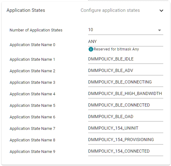
The stack states are defined in the file ti_dmm_application_policy, which is
generated by SysConfig. You can find this file under the
{configuration}/syscfg/ folder, after running the build step once.
Having a separate provisioning state allows an operator to modify some network parameters such as PANID, channel, security keys, etc during the uninitialized state via the BLE Central device (smart phone). Then via the BLE Central device again, trigger the provisioning state so that the sensor can successfully join only the network you wish it to join. This functionality enables easier configuration and therefor provisioning of a network. This lab will cover in detail how to perform the provisioning steps.
Task 1 – Setup the DMM TI 15.4 Sensor
Start by flashing the dmm_154sensor_remote_display_app project onto the DMM
device. Open and connect a terminal program to see the serial output from the
device, as described in the BLE Fundamentals SimpleLink Academy
lab.
When connected you should see the device output the following on the serial connection:
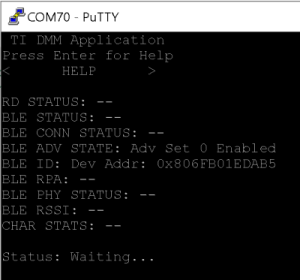
You now have a device that runs both the TI 15.4 sensor and the BLE Peripheral projects simultaneously. You can verify that your device is advertising over Bluetooth LE with a smart phone. Steps for connecting to a smart phone are given in the BLE Fundamentals SimpleLink Academy lab.
The device will advertise with the name "DMM 15.4 Sensor RD" or using the name chosen following the group training recommendations, as seen below.
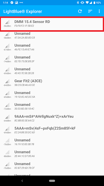
If you cannot find your device in your Bluetooth LE explorer app due to the fact that there are many devices advertising, then use the search feature to limit the displayed list.
Still cannot find your device?
It is possible that your smart phone has cached some old scan responses, device names, etc. To clear this cache, go to your phones Bluetooth settings and forget the device that corresponds to your board.
The BLE app asks for a PIN?
In order to read/write some of the characteristics in the BLE GATT for the TI 15.4 Sensor node, the Bluetooth LE explorer app may ask you for a PIN. This is because a security feature has been enabled that encrypts the connection.
The PIN is displayed in the terminal window when you ran the device. After you have paired and bonded once, then you shouldn't be asked for the PIN again.
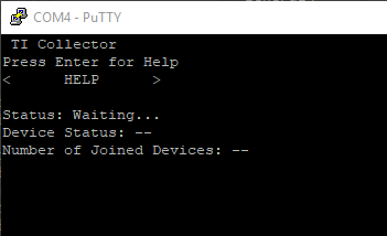
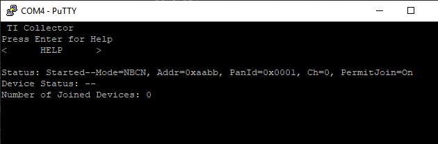
Task 2 – Setup the TI 15.4 Collector
The TI 15.4 Sensor application running on the DMM device is acting as a sensor. We need a TI 15.4 Collector to connect to it in order to see the Sub-1 GHz network. Setting up a TI 15.4 Collector is described in the SimpleLink Academy module 15.4 Stack Sensor and Collector.
Remember that when you start the TI 15.4 Collector, it will tell you which channel it has been started on.
Group training
Pay attention to the channel depending on the group training changes.
Quiz
Why doesn't the sensor automatically connect to the collector as the DMM device did in the DMM Fundamentals lab?
Task 3 – Provision the DMM Device
Now the collector is as well plugged in and powered up – you might notice that the sensor does not automatically connect to the collector as the DMM device in the DMM Fundamentals did. This is for three reasons.
The DMM TI 15.4 Sensor has not been configured for the correct frequency band, channel, and PAN ID (if the TI 15.4 Collector's defaults has been modified).
The TI 15.4 Collector's network has yet to be opened.
The DMM TI 15.4 Sensor has yet entered the provisioning state mentioned above.
If you modified the Collector's defaults as above, you will need to resolve issue number 1. Regardless, issue numbers 2 and 3 will need to be resolved.
You will do the same to the DMM sensor project as you did for the collector project. The file changes are similar for both the frequency band, channel, and PAN ID. Please complete this step now.
Open TI 15.4 Collector's Network
Follow instructions from 15.4 Stack Sensor and Collector. You will see the
following output after the network has been opened, i.e. PermitJoin=On.
This now means we can provision the DMM Device and namely the DMM TI 15.4 Sensor portion of it into the TI 15.4 Collector's network.
Provision the DMM TI 15.4 Sensor
Using your smart phone again, connect to the DMM Device if it isn't already and take a look at the provisioning Characteristics that are displayed.
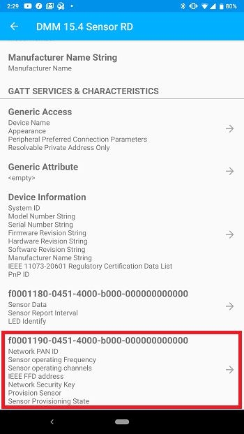
Here we can set the provisioning characteristics to match the network parameters on the TI 15.4 Collector. If no changes were made to the TI 15.4 Sensor and Collector then the default values will succeed.
Once you have the correct network parameters for your scenario, again, the default 15.4 Sensor settings will match the default settings for the TI 15.4 Collector. It is now time to provision the Sensor.
Follow the instructions in the project README under the Provisioning The 15.4 Sensor to A Network section. You will then be able to see that the DMM Device and TI 15.4 Collector device both show that a connection has occurred between them!
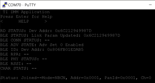
The DMM device will show on the serial output that the current status of the
TI 15.4 Sensor is Joined, which means it has connected to the TI 15.4
Collector.
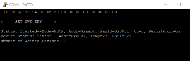
The TI 15.4 Collector will show that a device has joined and in this case the
TI 15.4 Collector has given the joining device the short address of 0x0001.
If we now wait for a couple minutes we will start to see the indication that
sensor data is being sent from the DMM device to the TI 15.4 Collector. Both
the Temp and RSSI fields for the Sensor is updated accordingly.
We now have two devices connected to the DMM device, over two different RF protocols. With your phone, you can use the Remote Display Service to interact with the TI 15.4 network. This is detailed in the project README.
Task 4 – Interact with the TI 15.4 Network via Bluetooth LE
Currently we have to wait 3 seconds to receive sensor data from the DMM device onto the TI 15.4 Collector. What if we want to change the report interval? Let's speed up the reporting interval of the DMM device to something faster.
Reconnect to the DMM device, if you are not already, and select the "Sensor Report Interval" characteristic from your smart phone and read the current value.
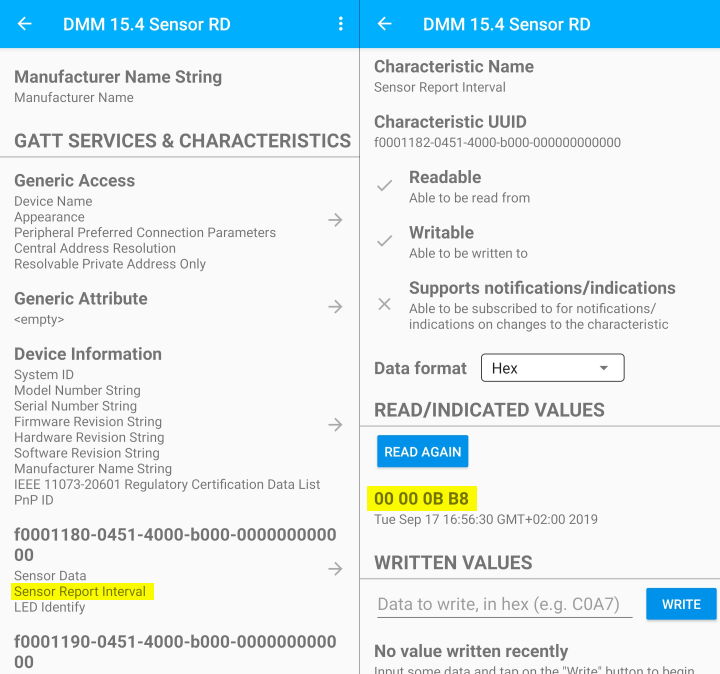
Hex format
The value read from the characteristic is in milliseconds, in addition to
being in hex format. In other words, 0x00000bb8 = 3000ms, which equals
3s.
Let's change this value to 1 second. What value should be written?
The correct value is 1s = 1000ms = 0x000003E8.
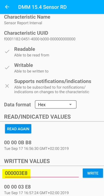
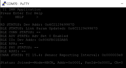
You will also see that the DMM device indicates the new Reporting Interval value.
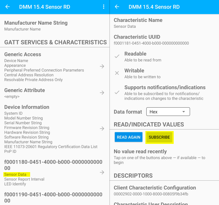
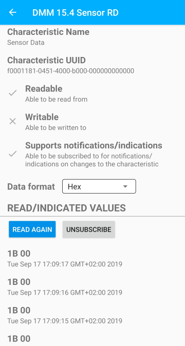
Now let's take advantage of the Subscription mode of a BLE Characteristic. Select the "Sensor Data" Characteristic and "Subscribe" to get a notification for every new value that gets written to it from the DMM device.
Quiz
How often do you expect to receive updates on the sensor data now?
Good work!
You have successfully setup and provisioned the DMM TI 15.4 Sensor + BLE demo. You viewed the Sensor Data, modified the Reporting Interval and subscribed to incoming Sensor Data from the DMM Device. All of which is made possible by DMM.
Task 5 – Creating the Custom Use Case
Now that we have explored the possibilities of the example and how it can be used, we can start to explore a path to a different, but still practical, use case.
Let's say you need a battery powered E-Lock project that unlocks/locks over Bluetooth LE when you are standing next to it with only your phone. At the same time, it is connected to a low power, long distance connection over TI 15.4 Sub-1 Ghz. Well, this is again a great use case for DMM!
We will be making changes step by step in order to convert this TI 15.4 Sensor & BLE Remote Display application into a TI 15.4 Sensor & BLE E-Lock application. Before we start making functional modifications to the example, let's first change some simple display text so that it looks the part.
Change Name Appearance
Replace the menu title on the serial output to print out something else.
This text is the define RD_MENU_TITLE located in
application/ble_remote_display/remote_display.c. Change this define to say
TI DMM E-Lock.
#define RD_MENU_TITLE " TI DMM E-Lock "
remote_display.c – Serial output menu title
Now that the serial output is done, let's make sure the Bluetooth LE advertisement also matches the menu title. This is done with SysConfig.
Open SysConfig by double clicking
dmm_154sensor_remote_display.syscfg.In SysConfig, navigate to
BLE→General Configuration→Device Name, and change the value ofDevice NametoTI DMM E-Lock.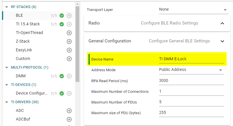
Save the SysConfig file.
Add the E-Lock Profile
We will need a characteristic profile to use for the E-lock. You can certainly
write your own for this, and even use the Custom Profile SimpleLink Academy
lab to help you do so, though for the sake of clarity and time you can use the
following two files: elock_gatt_profile.c and elock_gatt_profile.h. Place
the new files into your project under software_stacks/ble_stack/profiles/.
/******************************************************************************

 @file  elock_gatt_profile.h

 @brief This file contains the E-Lock GATT profile definitions and prototypes
        prototypes.

 ******************************************************************************/


#ifndef ELOCKGATTPROFILE_H
#define ELOCKGATTPROFILE_H

#ifdef __cplusplus
extern "C"
{
#endif

/*********************************************************************
 * INCLUDES
 */

/*********************************************************************
 * CONSTANTS
 */

// Profile Parameters
#define ELOCKPROFILE_CHAR1                   0  // RW uint8 - Profile Characteristic 1 value

// E-Lock Profile Service UUID
#define ELOCKPROFILE_SERV_UUID               0xFFF0

// Key Pressed UUID
#define ELOCKPROFILE_CHAR1_UUID            0xFFF1

// Elock Keys Profile Services bit fields
#define ELOCKPROFILE_SERVICE               0x00000001

/*********************************************************************
 * TYPEDEFS
 */


/*********************************************************************
 * MACROS
 */

/*********************************************************************
 * Profile Callbacks
 */

// Callback when a characteristic value has changed
typedef void (*elockProfileChange_t)( uint8 paramID );

typedef struct
{
  elockProfileChange_t        pfnElockProfileChange;  // Called when characteristic value changes
} elockProfileCBs_t;


/*********************************************************************
 * API FUNCTIONS
 */


/*
 * ElockProfile_AddService- Initializes the Elock GATT Profile service by registering
 *          GATT attributes with the GATT server.
 *
 * @param   services - services to add. This is a bit map and can
 *                     contain more than one service.
 */

extern bStatus_t ElockProfile_AddService( uint32 services );

/*
 * ElockProfile_RegisterAppCBs - Registers the application callback function.
 *                    Only call this function once.
 *
 *    appCallbacks - pointer to application callbacks.
 */
extern bStatus_t ElockProfile_RegisterAppCBs( elockProfileCBs_t *appCallbacks );

/*
 * ElockProfile_SetParameter - Set a Elock GATT Profile parameter.
 *
 *    param - Profile parameter ID
 *    len - length of data to right
 *    value - pointer to data to write.  This is dependent on
 *          the parameter ID and WILL be cast to the appropriate
 *          data type (example: data type of uint16 will be cast to
 *          uint16 pointer).
 */
extern bStatus_t ElockProfile_SetParameter( uint8 param, uint8 len, void *value );

/*
 * ElockProfile_GetParameter - Get a Elock GATT Profile parameter.
 *
 *    param - Profile parameter ID
 *    value - pointer to data to write.  This is dependent on
 *          the parameter ID and WILL be cast to the appropriate
 *          data type (example: data type of uint16 will be cast to
 *          uint16 pointer).
 */
extern bStatus_t ElockProfile_GetParameter( uint8 param, void *value );


/*********************************************************************
*********************************************************************/

#ifdef __cplusplus
}
#endif

#endif /* SIMPLEGATTPROFILE_H */
elock_gatt_profile.h
/******************************************************************************

 @file  elock_gatt_profile.c

 @brief This file contains the E-Lock GATT profile sample GATT service profile
        for use with the BLE sample application.

****************************************************************************/

/*********************************************************************
 * INCLUDES
 */
#include <string.h>
#include <icall.h>
#include "util.h"
/* This Header file contains all BLE API and icall structure definition */
#include "icall_ble_api.h"

#include "elock_gatt_profile.h"


/*********************************************************************
 * MACROS
 */

/*********************************************************************
 * CONSTANTS
 */

#define SERVAPP_NUM_ATTR_SUPPORTED        4

/*********************************************************************
 * TYPEDEFS
 */

/*********************************************************************
 * GLOBAL VARIABLES
 */
// Elock GATT Profile Service UUID: 0xFFF0
CONST uint8 elockProfileServUUID[ATT_BT_UUID_SIZE] =
{
  LO_UINT16(ELOCKPROFILE_SERV_UUID), HI_UINT16(ELOCKPROFILE_SERV_UUID)
};

// Characteristic 1 UUID: 0xFFF1
CONST uint8 elockProfilechar1UUID[ATT_BT_UUID_SIZE] =
{
  LO_UINT16(ELOCKPROFILE_CHAR1_UUID), HI_UINT16(ELOCKPROFILE_CHAR1_UUID)
};

/*********************************************************************
 * EXTERNAL VARIABLES
 */

/*********************************************************************
 * EXTERNAL FUNCTIONS
 */

/*********************************************************************
 * LOCAL VARIABLES
 */

static elockProfileCBs_t *elockProfile_AppCBs = NULL;

/*********************************************************************
 * Profile Attributes - variables
 */

// Elock Profile Service attribute
static CONST gattAttrType_t elockProfileService = { ATT_BT_UUID_SIZE, elockProfileServUUID };


// Elock Profile Characteristic 1 Properties
static uint8 elockProfileChar1Props = GATT_PROP_READ | GATT_PROP_WRITE;

// Characteristic 1 Value
static uint8 elockProfileChar1 = 0;

// Elock Profile Characteristic 1 User Description
static uint8 elockProfileChar1UserDesp[17] = "Lock";
/*********************************************************************
 * Profile Attributes - Table
 */

static gattAttribute_t elockProfileAttrTbl[SERVAPP_NUM_ATTR_SUPPORTED] =
{
 // Elock Profile Service
 {
  { ATT_BT_UUID_SIZE, primaryServiceUUID }, /* type */
  GATT_PERMIT_READ,                         /* permissions */
  0,                                        /* handle */
  (uint8 *)&elockProfileService            /* pValue */
 },

 // Characteristic 1 Declaration
 {
  { ATT_BT_UUID_SIZE, characterUUID },
  GATT_PERMIT_READ,
  0,
  &elockProfileChar1Props
 },

 // Characteristic Value 1
 {
  { ATT_BT_UUID_SIZE, elockProfilechar1UUID },
  GATT_PERMIT_READ | GATT_PERMIT_WRITE,
  0,
  (uint8 *)&elockProfileChar1
 },

 // Characteristic 1 User Description
 {
  { ATT_BT_UUID_SIZE, charUserDescUUID },
  GATT_PERMIT_READ,
  0,
  elockProfileChar1UserDesp
 },
};

/*********************************************************************
 * LOCAL FUNCTIONS
 */
static bStatus_t elockProfile_ReadAttrCB(uint16_t connHandle,
                                          gattAttribute_t *pAttr,
                                          uint8_t *pValue, uint16_t *pLen,
                                          uint16_t offset, uint16_t maxLen,
                                          uint8_t method);
static bStatus_t elockProfile_WriteAttrCB(uint16_t connHandle,
                                           gattAttribute_t *pAttr,
                                           uint8_t *pValue, uint16_t len,
                                           uint16_t offset, uint8_t method);

/*********************************************************************
 * PROFILE CALLBACKS
 */

// Elock Profile Service Callbacks
// Note: When an operation on a characteristic requires authorization and
// pfnAuthorizeAttrCB is not defined for that characteristic's service, the
// Stack will report a status of ATT_ERR_UNLIKELY to the client.  When an
// operation on a characteristic requires authorization the Stack will call
// pfnAuthorizeAttrCB to check a client's authorization prior to calling
// pfnReadAttrCB or pfnWriteAttrCB, so no checks for authorization need to be
// made within these functions.
CONST gattServiceCBs_t elockProfileCBs =
{
  elockProfile_ReadAttrCB,  // Read callback function pointer
  elockProfile_WriteAttrCB, // Write callback function pointer
  NULL                       // Authorization callback function pointer
};

/*********************************************************************
 * PUBLIC FUNCTIONS
 */

/*********************************************************************
 * @fn      ElockProfile_AddService
 *
 * @brief   Initializes the Elock Profile service by registering
 *          GATT attributes with the GATT server.
 *
 * @param   services - services to add. This is a bit map and can
 *                     contain more than one service.
 *
 * @return  Success or Failure
 */
bStatus_t ElockProfile_AddService( uint32 services )
{
  uint8 status;

  if ( services & ELOCKPROFILE_SERVICE )
  {
    // Register GATT attribute list and CBs with GATT Server App
    status = GATTServApp_RegisterService( elockProfileAttrTbl,
                                          GATT_NUM_ATTRS( elockProfileAttrTbl ),
                                          GATT_MAX_ENCRYPT_KEY_SIZE,
                                          &elockProfileCBs );
  }
  else
  {
    status = SUCCESS;
  }

  return ( status );
}

/*********************************************************************
 * @fn      ElockProfile_RegisterAppCBs
 *
 * @brief   Registers the application callback function. Only call
 *          this function once.
 *
 * @param   callbacks - pointer to application callbacks.
 *
 * @return  SUCCESS or bleAlreadyInRequestedMode
 */
bStatus_t ElockProfile_RegisterAppCBs( elockProfileCBs_t *appCallbacks )
{
  if ( appCallbacks )
  {
    elockProfile_AppCBs = appCallbacks;

    return ( SUCCESS );
  }
  else
  {
    return ( bleAlreadyInRequestedMode );
  }
}

/*********************************************************************
 * @fn      ElockProfile_SetParameter
 *
 * @brief   Set a Elock Profile parameter.
 *
 * @param   param - Profile parameter ID
 * @param   len - length of data to write
 * @param   value - pointer to data to write.  This is dependent on
 *          the parameter ID and WILL be cast to the appropriate
 *          data type (example: data type of uint16 will be cast to
 *          uint16 pointer).
 *
 * @return  bStatus_t
 */
bStatus_t ElockProfile_SetParameter( uint8 param, uint8 len, void *value )
{
  bStatus_t ret = SUCCESS;
  switch ( param )
  {
    case ELOCKPROFILE_CHAR1:
      if ( len == sizeof ( uint8 ) )
      {
        elockProfileChar1 = *((uint8*)value);
      }
      else
      {
        ret = bleInvalidRange;
      }
      break;

    default:
      ret = INVALIDPARAMETER;
      break;
  }

  return ( ret );
}

/*********************************************************************
 * @fn      ElockProfile_GetParameter
 *
 * @brief   Get a Elock Profile parameter.
 *
 * @param   param - Profile parameter ID
 * @param   value - pointer to data to put.  This is dependent on
 *          the parameter ID and WILL be cast to the appropriate
 *          data type (example: data type of uint16 will be cast to
 *          uint16 pointer).
 *
 * @return  bStatus_t
 */
bStatus_t ElockProfile_GetParameter( uint8 param, void *value )
{
  bStatus_t ret = SUCCESS;
  switch ( param )
  {
    case ELOCKPROFILE_CHAR1:
      *((uint8*)value) = elockProfileChar1;
      break;
    default:
      ret = INVALIDPARAMETER;
      break;
  }

  return ( ret );
}

/*********************************************************************
 * @fn          elockProfile_ReadAttrCB
 *
 * @brief       Read an attribute.
 *
 * @param       connHandle - connection message was received on
 * @param       pAttr - pointer to attribute
 * @param       pValue - pointer to data to be read
 * @param       pLen - length of data to be read
 * @param       offset - offset of the first octet to be read
 * @param       maxLen - maximum length of data to be read
 * @param       method - type of read message
 *
 * @return      SUCCESS, blePending or Failure
 */
static bStatus_t elockProfile_ReadAttrCB(uint16_t connHandle,
                                          gattAttribute_t *pAttr,
                                          uint8_t *pValue, uint16_t *pLen,
                                          uint16_t offset, uint16_t maxLen,
                                          uint8_t method)
{
  bStatus_t status = SUCCESS;

  // Make sure it's not a blob operation (no attributes in the profile are long)
  if ( offset > 0 )
  {
    return ( ATT_ERR_ATTR_NOT_LONG );
  }

  if ( pAttr->type.len == ATT_BT_UUID_SIZE )
  {
    // 16-bit UUID
    uint16 uuid = BUILD_UINT16( pAttr->type.uuid[0], pAttr->type.uuid[1]);
    switch ( uuid )
    {
      // No need for "GATT_SERVICE_UUID" or "GATT_CLIENT_CHAR_CFG_UUID" cases;
      // gattserverapp handles those reads

      // characteristics 1 has read permissions
      case ELOCKPROFILE_CHAR1_UUID:
          *pLen = sizeof(elockProfileChar1);
          VOID  memcpy(pValue, pAttr->pValue, sizeof(elockProfileChar1));
          break;
      default:
        // Should never get here!
        *pLen = 0;
        status = ATT_ERR_ATTR_NOT_FOUND;
        break;
    }
  }
  else
  {
    // 128-bit UUID
    *pLen = 0;
    status = ATT_ERR_INVALID_HANDLE;
  }

  return ( status );
}

/*********************************************************************
 * @fn      elockProfile_WriteAttrCB
 *
 * @brief   Validate attribute data prior to a write operation
 *
 * @param   connHandle - connection message was received on
 * @param   pAttr - pointer to attribute
 * @param   pValue - pointer to data to be written
 * @param   len - length of data
 * @param   offset - offset of the first octet to be written
 * @param   method - type of write message
 *
 * @return  SUCCESS, blePending or Failure
 */
static bStatus_t elockProfile_WriteAttrCB(uint16_t connHandle,
                                           gattAttribute_t *pAttr,
                                           uint8_t *pValue, uint16_t len,
                                           uint16_t offset, uint8_t method)
{
  bStatus_t status = SUCCESS;
  uint8 notifyApp = 0xFF;

  if ( pAttr->type.len == ATT_BT_UUID_SIZE )
  {
    // 16-bit UUID
    uint16 uuid = BUILD_UINT16( pAttr->type.uuid[0], pAttr->type.uuid[1]);
    switch ( uuid )
    {
      case ELOCKPROFILE_CHAR1_UUID:
          //Validate the value
          // Make sure it's not a blob oper
          if ( offset == 0 )
          {
            if ( len != 1 )
            {
              status = ATT_ERR_INVALID_VALUE_SIZE;
            }
          }
          else
          {
            status = ATT_ERR_ATTR_NOT_LONG;
          }

          //Write the value
          if ( status == SUCCESS )
          {
            uint8 *pCurValue = (uint8 *)pAttr->pValue;
            *pCurValue = pValue[0];
            notifyApp = ELOCKPROFILE_CHAR1;
          }
          break;

      case GATT_CLIENT_CHAR_CFG_UUID:
        status = GATTServApp_ProcessCCCWriteReq( connHandle, pAttr, pValue, len,
                                                 offset, GATT_CLIENT_CFG_NOTIFY );
        break;

      default:
        // Should never get here!
        status = ATT_ERR_ATTR_NOT_FOUND;
        break;
    }
  }
  else
  {
    // 128-bit UUID
    status = ATT_ERR_INVALID_HANDLE;
  }

  // If a characteristic value changed then callback function to notify application of change
  if ( (notifyApp != 0xFF ) && elockProfile_AppCBs && elockProfile_AppCBs->pfnElockProfileChange )
  {
    elockProfile_AppCBs->pfnElockProfileChange( notifyApp );
  }

  return ( status );
}

/*********************************************************************
*********************************************************************/
elock_gatt_profile.c
In order for the project to find the recently added files, add the following include search paths in the project properties:
Navigate to
Project Properties→Build→ARM Compiler→Include Options.Add the following search paths:
${PROJECT_ROOT}/software_stacks/ble_stack/profiles
The E-lock profile has one single service which has one single read/write
lock characteristic. When writing 1 to the lock characteristic the
E-lock should be locked. When writing 0 to the lock characteristic the
E-lock should be unlocked. In the absence of a physical lock to actuate, we
will make use of the remote display we're already using to display the state
changes.
The profile is initialized by calling the ElockProfile_AddService() function
and application callbacks are registered with ElockProfile_RegisterAppCBs().
The application callback will be invoked when the lock characteristic
changes.
Now it is time to integrate the E-lock profile to the remote display. Do the
following modifications to remote_display.c:
Include the
elock_gatt_profile.hheader file at the top.#include "elock_gatt_profile.h"remote_display.c – Include header file
Create the E-lock profile callback function and struct. This function will be called by the E-lock profile when a characteristic value change has occurred. It will then enqueue an application message indicating it as an
ELOCK_CHAR_CHANGE_EVTso that when we get around to processing this message we will know what event it corresponds to./********************************************************************* * LOCAL FUNCTIONS */ static void Elock_charValueChangeCB(uint8_t paramId); /********************************************************************* * PROFILE CALLBACKS */ // Elock GATT Profile Callbacks static elockProfileCBs_t Elock_simpleProfileCBs = { Elock_charValueChangeCB // Elock GATT Characteristic value change callback }; /********************************************************************* * PUBLIC FUNCTIONS */ static void Elock_charValueChangeCB(uint8_t paramId) { uint8_t *pValue = ICall_malloc(sizeof(uint8_t)); if (pValue) { *pValue = paramId; RemoteDisplay_enqueueMsg(ELOCK_CHAR_CHANGE_EVT, pValue); } }remote_display.c – E-lock profile application callback
Create an
ELOCK_CHAR_CHANGE_EVTflag next to the other Application Event flags. Make sure theELOCK_CHAR_CHANGE_EVTis assigned a unique event ID.// Application events #define RD_STATE_CHANGE_EVT 0 #define RD_CHAR_CHANGE_EVT 1 /* ... code omitted ... */ #define RD_UPDATE_DEVICE_UPDATE_EVT 15 #define RD_CONN_EVT 16 #define SM_CHAR_CHANGE_EVT 17 #define SM_SENSOR_STATE_CHANGE_EVT 18 #ifdef DISPLAY_PER_STATS #define RD_UPDATE_PER_EVT 19 #define RD_PER_RESET_EVT 20 #define RD_PER_READ_EVT 21 #endif /* DISPLAY_PER_STATS */ #if defined(BLOCK_MODE_TEST) && !defined(CUI_DISABLE) #define RD_BLOCK_MODE_EVT 22 #endif /* defined(BLOCK_MODE_TEST) && !defined(CUI_DISABLE) */ /* <<< ADD EVENT HERE >>> */ #define ELOCK_CHAR_CHANGE_EVT 23remote_display.c – Add new application event
Add a call to
ElockProfile_AddService()with the existing*_AddService()calls in theRemoteDisplay_init()function.// Initialize GATT attributes GGS_AddService(GATT_ALL_SERVICES); // GAP GATT Service GATTServApp_AddService(GATT_ALL_SERVICES); // GATT Service DevInfo_AddService(); // Device Information Service RemoteDisplay_AddService(GATT_ALL_SERVICES); // Remote Display GATT Profile #ifdef DMM_COLLECTOR NetworkDeviceProfile_AddService(GATT_ALL_SERVICES); // Network DEvice GATT Profile #endif ProvisioningProfile_AddService(GATT_ALL_SERVICES); // Provisioning GATT Profile /* <<< ADD CALL HERE >>> */ ElockProfile_AddService(GATT_ALL_SERVICES); // Elock GATT Profileremote_display.c – Add E-lock service
Setup the E-lock profile characteristic values and register its application callbacks right below the
ElockProfile_AddService()call we just added. In this case, we don't want our lock to be open when we startup, so we will callElockProfile_SetParameter()with a value of1so we can actually lock our lock.// Setup the E-lock profile characteristic value to locked uint8_t elockLocked = 1; ElockProfile_SetParameter(ELOCKPROFILE_CHAR1, sizeof(elockLocked), &elockLocked); // Register app callbacks with E-lock profile ElockProfile_RegisterAppCBs(&Elock_simpleProfileCBs);remote_display.c – Right below new
ElockProfile_AddService()callBuild and flash the DMM device. You will be able to see the new Characteristics from the E-lock profile. If you try to read from the characteristics you will see the current value ìs
1, which is the default value we set previously. However, you will see that reading and writing to the characteristic does not do much on the remote display. We have to add some code to react to the read/writes that we perform on this new profile.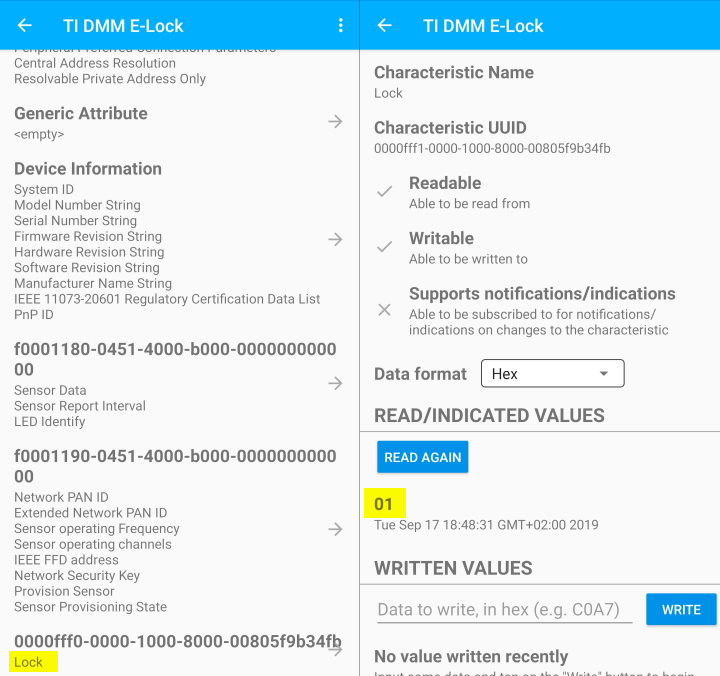
Profile not showing up?
It is possible that your smart phone has cached old profiles from the previous connection. To clear this cache, go to your phones Bluetooth settings, forget the device that corresponds to your board, and try again.
Add the
RemoteDisplay_processElockCharValueChangeEvt()function, which will act on thelockcharacteristic changing.CUI_clientHandle_t remoteDisplayCuiHndl; /* ... code omitted .. */ /* <<< ADD THIS >>> */ uint32_t rdStatusLineElockStatus; /********************************************************************* * LOCAL FUNCTIONS */ /* <<< ADD THIS >>> */ static void RemoteDisplay_processElockCharValueChangeEvt(uint8_t paramId); /********************************************************************* * LOCAL FUNCTIONS */ static void RemoteDisplay_init(void) { ... /* <<< CHANGE THIS >>> */ clientParams.maxStatusLines = 10; CUI_registerMenu(remoteDisplayCuiHndl, &remoteDisplayMainMenu); /* ... code omitted ... */ /* <<< ADD THIS >>> */ CUI_statusLineResourceRequest(remoteDisplayCuiHndl, "E-LOCK STATUS", false, &rdStatusLineElockStatus); ... } static void RemoteDisplay_processAppMsg(rdEvt_t *pMsg) { ... switch (pMsg->event) { /* ... code omitted ... */ /* <<< ADD THIS >>> */ case ELOCK_CHAR_CHANGE_EVT: RemoteDisplay_processElockCharValueChangeEvt(*(uint8_t*)(pMsg->pData)); break; /* ... code omitted ... */ } ... } /* <<< ADD THIS >>> */ static void RemoteDisplay_processElockCharValueChangeEvt(uint8_t paramId) { // Elock profile new parameters uint8_t newLockValue; char *statusFmt; bStatus_t ret; switch (paramId) { // Provisioning profile characteristics case ELOCKPROFILE_CHAR1: // Obtain current value of parameter from profile ret = ElockProfile_GetParameter(ELOCKPROFILE_CHAR1, &newLockValue); if (ret == SUCCESS) { // Print out status statusFmt = (newLockValue) ? "Locked" : "Unlocked"; CUI_statusLinePrintf(remoteDisplayCuiHndl, rdStatusLineElockStatus, statusFmt); } break; default: // should not reach here! break; } }remote_display.c – Add the
RemoteDisplay_processElockCharValueChangeEvt()Build and flash the DMM device.
Test the E-Lock Profile
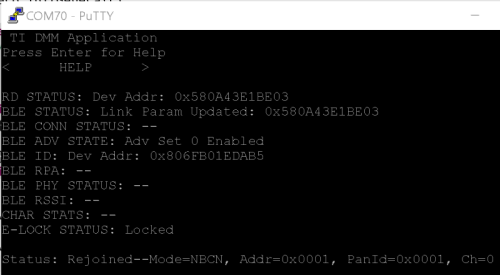
After building and flashing with those last few updates, you will now be able to modify the E-lock value through the E-lock profile,
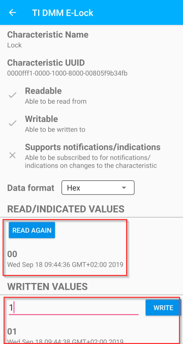
while getting the updates displayed on the serial output.
Good work!
Congratulations! You have now added some pseudo E-Lock functionality to your DMM project. Don't forget that this is a DMM project. The existing TI 15.4 sensor/collector functionality stands the same and will continue to work just as it was before.
This work is licensed under a Creative Commons Attribution-NonCommercial-NoDerivatives 4.0 International License.