Introduction
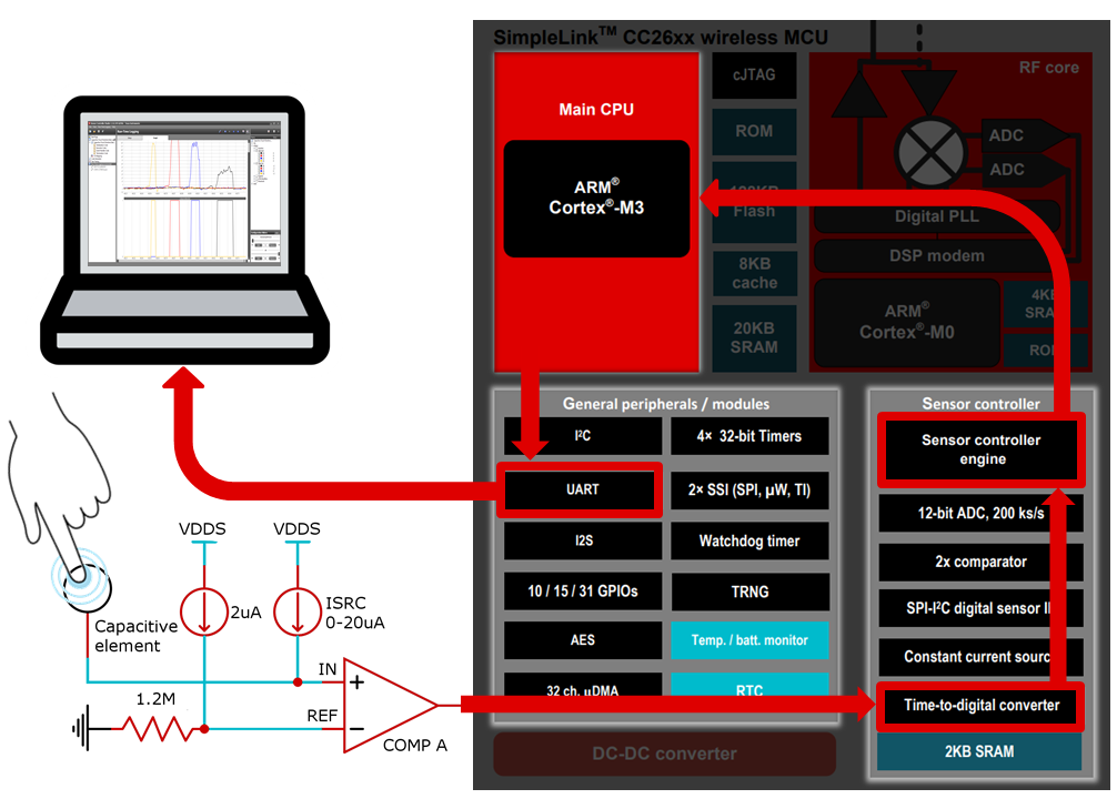
This training will show how to use the Sensor Controller (SC) to do Capacitive Sensing and how to use the run time logging. Capasitive sensing is used in applications where you need touch capabilities but can't have physical buttons or a metallic touch surface. A typical user case can be a panel with buttons and sliders implemented as part of the PCB that is completely incapsulated in plastic which can be mounted in exposed enviorements and reduce cost.
The data will be displayed as graphs using the Run-Time Logging functionality in Sensor Controller Studio (SCS).
Reference voltage
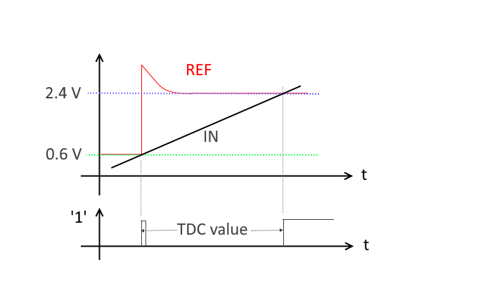
The reference voltages is selected according to the supply voltage on a Launchpad. For systems that could have a lower supply voltage it could be required to adjust the reference voltage if the supply voltage is lower than 3.3 V.
The point where the TDC starts to count is given as Rext || 400 kohm x 2 uA. The point where the TDC stops to count is given as Rext x 2 uA where Rext is the external resistor. This voltage should be at least 0.5 V lower than VDDS:
Compatible SimpleLink MCU LaunchPad kits
This workshop can be completed with any one of the SimpleLink™ Wireless MCU with Sensor Controller devices described in the table below. Install the required Associated SimpleLink Software Development Kit matching your device. More details on LaunchPads please visit the LaunchPad overview page.
Prerequisites
Software for desktop development
- SCS 2.5.0 or newer. You can find version info in the menu
Help->About Sensor Controller Studio
Hardware
BOOSTXL-ULPSENSE BoosterPack for capacitive sensing
One of the following Launchpads:
- LAUNCHXL-CC1312R1,
- LAUNCHXL-CC1350,
- LAUNCHXL-CC1352R1,
- LAUNCHXL-CC1352P,
- LAUNCHXL-CC26x2R1,
Micro-USB cable for LaunchPad
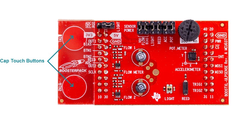
The picture below shows the BOOSTXL-ULPSENSE with emphasizes on the two capacitive touch buttons.
Task 0 – Open the SCS Project
- Start SCS and locate the
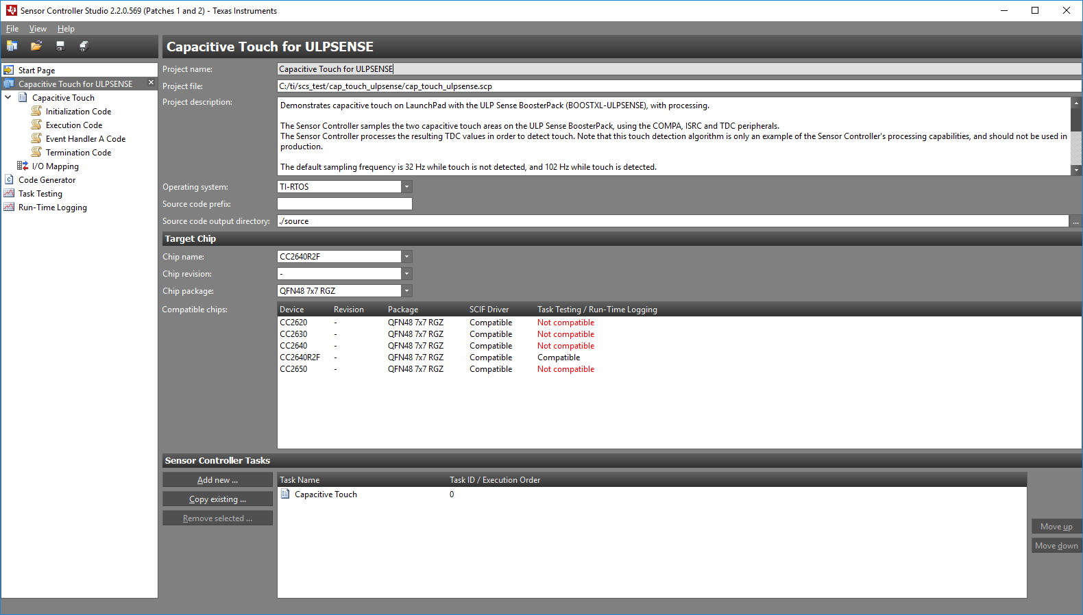
Start Page - Under Examples, double click on "Capacitive Touch" under "LaunchPad + ULP Sense BoosterPack"
- Make sure that
TI-RTOSis chosen as the Operating System and that the chip you are using is chosen as the Target Chip Name
You should now have something similar to this.
Connect your LaunchPad with the USB cable to the computer. Connect the BOOSTXL-ULPSENSE on top of the LaunchPad. The two capacitive sensing buttons are connected to DIO26 and DIO27.
Task Resources
All resources are already setup in the example and no extra steps are required to run the example. This section goes through the resources used in the example. To view the resources used, go to Task Resources. This can be accessed by clicking the task name in the project view.
The following resources are needed:
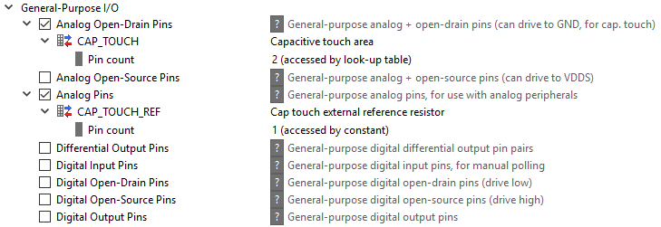
- Analog Open-Drain Pins
- Analog Pins (see "Deciding Capacitive Touch Input Pins" below)
- COMPA
- ISRC
- TDC
- Multi-buffered Output Data Exchange, "Buffer Count=3" and "Prevent overflow at buffer switch = enable", everything else disabled
- Peripheral Sharing
- System CPU Alert
- Timer Event Trigger
- Delay Insertion
- Math and Logic
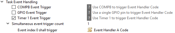
The Sensor Controller Task is executed at a dynamic interval. This is done by using Timer 1 to trigger
Event Handler A Code.
This example uses two capacitive touch buttons.
The device has 8 analog pins, but one of them are used for an external resistor for the internal current reference, which means up to 7 pins are available for capacitive buttons. If the requirement is to use a different number of buttons than used in this example , go to "Analog Open-Drain Pins" and the line "Pin count 2". Change this to something between 1 and 7. The "Pin count" under "Analog Pins" is for the reference resistor. Keep its default value 1.
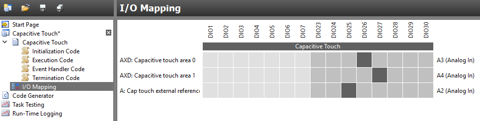
I/O Mapping
To see which pins are used by the example or change the pin mapping, go to "I/O mapping".
Depeding on how many capacitive sensing inputs selected, the I/O Mapping will differ. A list of compatible input pins are shown below. These are the pins that are described as "analog" in the datasheet.
- DIO23
- DIO24
- DIO25
- DIO26
- DIO27
- DIO28
- DIO29
- DIO30
When using the ULPSENSE boosterpack, the reference resistor is mapped to DIO25, and the capacitive buttons to DIO27 and DIO28 respectively. For a custom product the resistor and capacitive button elements can be mapped to any of the above listed pins.
Available pins
Some CC13xx Launchpads use DIO28, DIO29 and DIO30 for control signals to other RF circuits on the Launchpad. The "board mapping" list in the lower part of the I/O Mapping window gives information if the pin is available or not.
Task 1 – Testing The Code Using The Run-Time Logging Tool
Task 1.1 - Get to know the GUI
Click the Run-Time Logging in the menu to the left. Connect to it by pressing
the connect symbol at the top, or press F12. When the LaunchPad has
successfully connected, click the Run symbol or press F5 in order
to start the logging.

- Connect
- Restart
- Run
- Pause
- Stop
- Auto-Scroll (have this activated in normal use)
- Auto-Scale
- Customize Graphs
Task 1.2 - Filtered data
A good place to start looking is at the raw TDC data. This is done by expanding
the output struct and click the box in front of pTdcValueRaw.
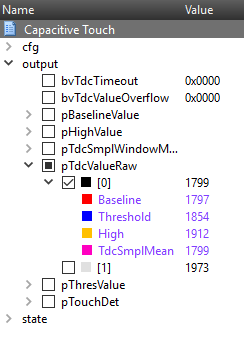
By pressing the capacitive element connected labeled BTN1 on the ULPSENSE boosterpack the pTdcValueRaw should increase. By touching the BTN1 the capacitance on this pin increase. This will increase the time it takes to charge this capacitance up to the reference voltage. The raw value is used to evaluate of the capacitive sensing element has been touched or not.
The raw data can be quite noisy, which the filtering algorithm will try to suppress the best it can.
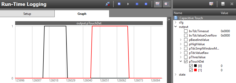
[0]is the true raw value read from the TDC. It's completely unfiltered.Baseline: this is the infinite impulse response of the long term average value of when no capacitive element is touched. This value is a dynamic value.Threshold: this is the value, to which the filtered value is compared, in order to evaluate touch. This is dynamic and is calculated asbaseline + 0.5 (highvalue - baseline).High: this is a filtered TDC value when you touch the capacitive touch element.TdcSmplMean: the resulting moving average value.
In order to see the Raw, Baseline, High, Threshold and TdcSmplMean
values for BTN2, open the corresponding pTdcValueRaw, pBaselineValue,
pHighValue, pThresValue, pTdcSmplWindowMeantab and click the box for
[1].
If you can't see any data or your graphs seems noisy:
The Run-Time Logging needs a high UART datarate. Check that the baud rate is set to 230400 in the Run-Time Logging window. Check that the plexiglas is mounted firmly on the PCB and that the boosterpack is fully attached to the launchpad.
Task 1.3 - Customize Graphs
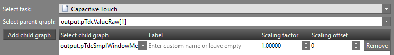
In order to add the corresponding graphs to the already existing view, use the
Customize Graphs option:
- Click
Customize Graphs - Select which graph you want to add child graphs to in the drop down for
Select parent graph, for exampleoutput.pTdcValueRaw[1] - Press
Add child graph - Select the child graph you want to add, for example
pTdcSmplWindowMean[1] - Repeat with graphs of your choice
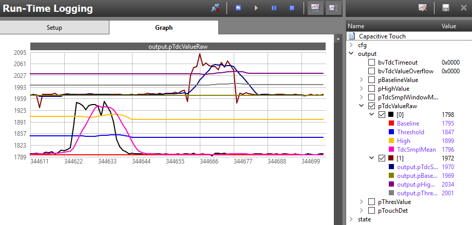
Here, we have added the corresponding graphs to BTN2 that were already added
for BTN1. This is useful when you want to compare different filter in the same
window rather than having one window for each filter.
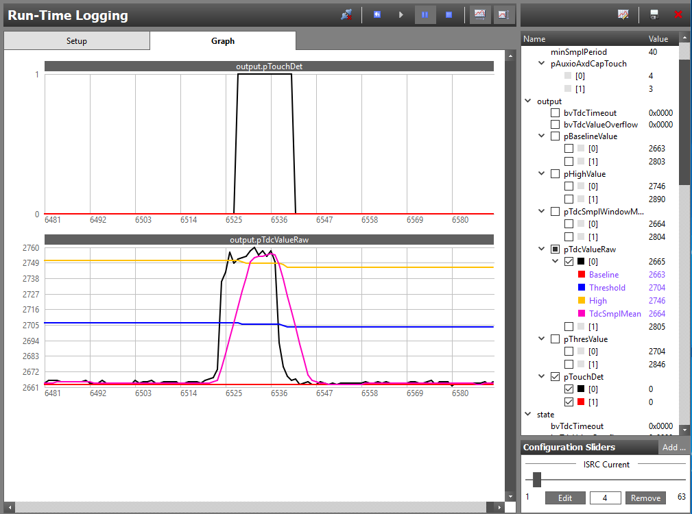
Notice that when the code detects a touch, the sample rate is increased. The variables controlling this are:
cfg.maxSamplePeriodfor the non-detect sample ratecfg.minSamplePeriodfor when the element is touched
This is to save power when no touch is being detected.
Task 1.4 - Detection
For most applications, a simple pressed/not pressed functionality is enough.
If the TdcSmplMean value exceeds the Threshold value, a detection is set
from 0 to 1. If you check the pTouchDet box a new graph window will open with
a binary value representing the touch.
If you want your pTouchDet graph to register faster or slower, this can be
done by changing the threshold value. By default it's:
// Set the touch detection threshold to 1/2 between the baseline and the high value
U16 thresValue = baselineValue + ((highValue - baselineValue) >> 1);
For example, change the right shifted >> 1 to something else in order to make
the division
larger/ smaller.
Great job!
You have now tested a basic capacitive touch algorithm using a SimpleLink device!
Task 2 – Trimming the Capacitive Touch Algorithm
If you're not using the BOOSTXL-ULPSENSE BoosterPack, but rather a custom hardware, you know that different touch elements have different sensitivity. This can cause the graphs to not react at all, or to be triggered at all times. Either way, trimming the current which is charging the capacitance might be able to save the day!
The less current that is charging the capacitor, the more sensitive the input becomes. Different register values will give different currents between 0.25 uA and 16.25 uA. The default value for the current slider is 4, which corresponds to 1 uA.
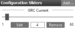
Everytime you change the value of the slider, you have to restart the run-time logging. Press the tool bar button or use F7.
Nice Job!
When you are satisfied with the current and voltage trimming, move on to Task 3 to see the inner workings of the algorithm.
Task 3 – A Closer Look At The SCS Code (Optional)
We are now ready to take a look at some key implementations in the code. If you at any moment want to read more about an API call, open Sensor Controller Studio > Help > Sensor Controller Studio Help, or press F1. As soon as the Help Viewer is open, you can use the search box to hopefully find the information you are looking for. The SCS help can also be found her
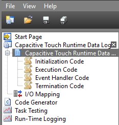
A Sensor Controller project is built up by code called at four different times:
| Panel Tab | Description |
|---|---|
 |
Code that will run once after initialization of task (scifStartTasksNbl()). |
 |
The Execution Code will run when scheduled (fwScheduleTask()). |
 |
Code that is triggered by a configured event (GPIO, COMPB or timer). |
 |
Termination code run once on task exit or never if the task runs forever. |
The Execution Code is empty since this project does not make use of any code scheduled by the TI-RTOS, but rather
triggered periodically by Timer A.
Initialization Code
We start with initialization of the pins we chose in the I/O mapping.
// Clamp all capactive touch pins to ground
for (U16 n = 0; n < PIN_COUNT; n++) {
    isrcClamp(cfg.pAuxioAxdCapTouch[n]);
}
The reference should not be pulled high at this point in the code.
// Do not drive the reference high
gpioClearOutput(AUXIO_AXS_CAP_TOUCH_REF);
In order to start the periodically called Event Handler A Code to do the actual TDC
readings we schedule its first execution by calling:
// Schedule the first execution
evhSetupTimer1Trigger(0, 1, 5);
Looking at the documentation we can see that the parameters are:
- evIndex - Event index to be triggered
- mant - Delay mantissa value (1-255). Resulting delay is mant * 2^exp [4 kHz ticks].
- exp - Delay exponent value (0-15). Resulting delay is mant * 2^exp [4 kHz ticks].
Looking again at this picture we can see that Event Index 0 will trigger our
Event Handler A Code. This explains the first parameter 0.
Event Handler A Code
As stated earlier there is no Execution Code, but rather the Event Handler
A Code periodical executed based on a timer. This whole block of code will run
every time the timer 1 is triggered.
- Peripherals are initialized
- Reference voltage is chosen
- The current charging the capacitance is set
- Clock source is chosen
- TDC is being read in a loop for each pin
- TDC value processing
- Output is generated
- Sample period is being calculated
- Peripherals are being released
- The next measurement is scheduled
The code uses three different types of data structures: cfg, state and
output.

cfgcontains the constant variables we initialize. They can be changed depending on your application but will never be updated runtime.statecontains variables that are dynamically updated between iterations in order for us to calculate the output variables.outputcontains the output variables that we can use for different application purposes.
Some of the code is self-explanatory, but the part about the data being filtered can be hard to grasp, which is why we have chosen to talk more about it here.
TDC value processing
The TDC value has to go through a series of post processing steps to detect if a button has been touched.
The two following figures gives a graphical representation of the flow.
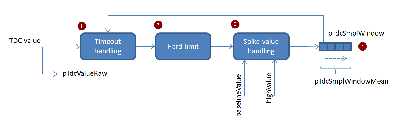
The processing steps are named and numbered and the following sections will show the code for the various steps.
Step 1: TDC timeout handling
Handle TDC timeout: Reuse last value until MAX_TDC_TIMEOUTS timeouts in a row, then it's an error. For the very first iteration the timeout count is initialized to MAX_TDC_TIMEOUTS - 1. The variable tdcTimeoutCount is available in the Run-Time Logging view for monitoring.
    // Handle TDC timeout: Reuse last value until MAX_TDC_TIMEOUTS timeouts in a row, then it's an error
    // For the very first iteration the timeout count is initialized to MAX_TDC_TIMEOUTS - 1
    U16 tdcTimeoutCount = state.pTdcTimeoutCount[n];
    if (isTdcDone == 1) {
        tdcTimeoutCount = 0;
    } else {
        tdcValueL = *pTdcSmplWindowPinBase;
        utilIncrAndSat(tdcTimeoutCount, MAX_TDC_TIMEOUTS; tdcTimeoutCount);
        if (tdcTimeoutCount == MAX_TDC_TIMEOUTS) {
            state.bvTdcTimeout |= 1 << n;
        }
    }
    state.pTdcTimeoutCount[n] = tdcTimeoutCount;
Step 2: Hard-limit
Hard-limit so that arithmetic overflow cannot occur. The variable bvTdcValueOverflow is available in the Run-Time Logging view for monitoring.
    // Handle TDC value overflow: Hard-limit so that arithmetic overflow cannot occur
    if (TDC_SMPL_WINDOW_EXP >= LOW_MEAN_WINDOW_EXP) {
        if (tdcValueL >= (0xFFFF >> TDC_SMPL_WINDOW_EXP)) {
            tdcValueL = 0xFFFF >> TDC_SMPL_WINDOW_EXP;
            state.bvTdcValueOverflow |= 1 << n;
        }
    } else {
        if (tdcValueL >= (0xFFFF >> LOW_MEAN_WINDOW_EXP)) {
            tdcValueL = 0xFFFF >> LOW_MEAN_WINDOW_EXP;
            state.bvTdcValueOverflow |= 1 << n;
        }
    }
Step 3: Spike value handling
This step filter away any raw TDC spikes. The value compared to the raw TDC data is calculated every iteration and is dependent on the last iterations baseline- and high value.
    // Handle TDC value spikes: Saturate the TDC value to a range around the current baseline
    if (state.startupIterCount > TDC_SMPL_WINDOW_SIZE) {

        // The TDC value's maximum deviation from the baseline is 1.25 * (filterHighVal - baseline)
        U16 baselineValue = state.pBaselineValue[n];
        U16 highBaselineDiff = state.pHighValue[n] - baselineValue;

        // Ensure that the TDC value is in the range [baseline - margin, baseline + 2 * margin]
        U16 minTdcValueL = baselineValue - highBaselineDiff;
        U16 maxTdcValueL = baselineValue + (highBaselineDiff << 1);
        if (tdcValueL < minTdcValueL) {
            tdcValueL = minTdcValueL;
        } else if (tdcValueL > maxTdcValueL) {
            tdcValueL = maxTdcValueL;
        }
    }
Step 4: pTdcSmplWindow
    // Finalize the TDC value window mean
    tdcSmplWindowMean += tdcValueL;
    tdcSmplWindowMean >>= TDC_SMPL_WINDOW_EXP;
    output.pTdcSmplWindowMean[n] = tdcSmplWindowMean;
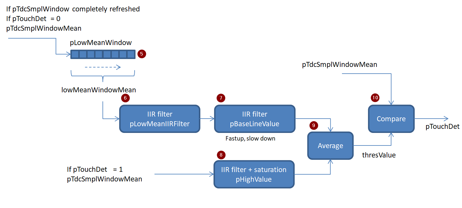
Step 5 and 6: pLowMeanWindow and IIR filter
These steps of the code are conditinal and will be performed each time the TDC value window has been replaced while not detecting a touch. First The lowMeanWindowMean is updated before the result is filtered through a IIR filter.
    // Each time the TDC value window has been replaced while not detecting a touch, add the
    // low TDC value window mean to the low mean window
    if (state.pTdcSmplLowCount[n] >= TDC_SMPL_WINDOW_SIZE) {
        ifnot (state.pTdcSmplLowCount[n] & (TDC_SMPL_WINDOW_SIZE - 1)) {

            // Shift the current low mean window, and calculate the mean value of the moved values
            U16* pLowMeanItem = pLowMeanWindowPinBase + (LOW_MEAN_WINDOW_SIZE - 2);
            U16 lowMeanWindowMean = 0;
            while (pLowMeanItem >= pLowMeanWindowPinBase) {
                U16 lowMeanItemValue = *(pLowMeanItem++);
                *pLowMeanItem = lowMeanItemValue;
                pLowMeanItem -= 2;

                // Add to the average, using the
                if (lowMeanItemValue == 0) {
                    lowMeanWindowMean += tdcSmplWindowMean;
                } else {
                    lowMeanWindowMean += lowMeanItemValue;
                }
            }

            // Insert the new TDC value window mean, and finalize the sum
            *pLowMeanWindowPinBase = tdcSmplWindowMean;
            lowMeanWindowMean += tdcSmplWindowMean;
            lowMeanWindowMean >>= LOW_MEAN_WINDOW_EXP;

            // Calculate the low mean value by IIR filtering
            if (state.startupIterCount < LOW_MEAN_IIR_UPDATE_PERIOD) {
                state.pLowMeanIirFilter[n] = lowMeanWindowMean;
            } else {
                iirFilter(state.pLowMeanIirFilter[n], lowMeanWindowMean, LOW_MEAN_IIR_DIV_EXP);
            }
        }
    }
Step 7/ step 8: Update pBaselineValue/ IIR filter
Dependent on the state of pTouchDet either step 7 (the if statement return true) or step 8 (the if staement return false) will be done.
if (state.pTouchDet[n] == 0) {

            // Update the baseline after a backoff period
            U16 lowMeanIirFilter = state.pLowMeanIirFilter[n];
            if (state.pTdcSmplLowCount[n] > (LOW_MEAN_IIR_UPDATE_PERIOD + BASELINE_UPDATE_PERIOD)) {

                // The baseline value tracks faster when going down than when going up
                if (lowMeanIirFilter < baselineValue) {
                    iirFilter(baselineValue, lowMeanIirFilter, 1);
                } else {
                    iirFilter(baselineValue, lowMeanIirFilter, 3);
                }
                state.pBaselineValue[n] = baselineValue;

                // Back off
                state.pTdcSmplLowCount[n] -= BASELINE_UPDATE_PERIOD;
            }

        // Otherwise ...
        } else {

            // Update the high value
            iirFilter(highValue, tdcSmplWindowMean, 4);
        }
Step 9: Update threashold value
output.pBaselineValue[n] = baselineValue;

        // Limit the high value to the range [baseline + 1/32, baseline + 1/4]
        U16 minHighValue = baselineValue + (baselineValue >> 5);
        if (highValue < minHighValue) {
            highValue = minHighValue;
        }
        U16 maxHighValue = baselineValue + (baselineValue >> 2);
        if (highValue > maxHighValue) {
            highValue = maxHighValue;
        }
        state.pHighValue[n] = highValue;
        output.pHighValue[n] = highValue;

        // Set the touch detection threshold to 1/2 between the baseline and the high value
        U16 thresValue = baselineValue + ((highValue - baselineValue) >> 1);
        output.pThresValue[n] = thresValue;
Step 10: Detect touch
Determine if a touch is detected or not by comparing with the threshold value. The sample time is also adjusted in this step.
// Detect touch
        U16 touchDetNow;
        if (tdcSmplWindowMean > thresValue){
            touchDetNow = 1;
            state.pTdcSmplLowCount[n] = 0;
            state.smplPeriod = cfg.minSmplPeriod;
        } else {
            touchDetNow = 0;
            state.pTdcSmplLowCount[n] += 1;
        }

        // Find whether we should generate any output
        if (touchDetNow != state.pTouchDet[n]) {
            state.pTouchDet[n] = touchDetNow;
            state.genOutput = 1;
        } else {
            state.genOutput |= touchDetNow;
        }
        output.pTouchDet[n] = touchDetNow;
Remaining code
The code not covered in the above is typically for initialization or error handling.
Schedule next iteration
At the bottom of the code you can see the same call as in the bottom of the initialization code.
// Schedule the next execution
evhSetupTimer1Trigger(0, state.smplPeriod, 0);
This line has to be called every time after each execution in order to schedule
for the next period. Here we can see that the state.smplPeriod is used in
order to dynamically set the sample time.
Termination Code
The Termination Code must call evhCancelTrigger() for each used event index. In
our case that is once again Event Index 0.
// Stop triggering the event handler code
evhCancelTrigger(0);
Job Well Done!
You should now have gained some insight in to how capacitive sensing works using the SCS Run-Time Logging tool.