Introduction
This workshop will show you how to use the Ultra-Low Power (ULP) Sense BoosterPack, combined with the Sensor Controller to create low-power applications. The LC Flow Meter and Reed Switch sensors will be used as part of the workshop. In addition, you will learn how to use EnergyTrace in Code Composer Studio to observe the current consumption of your application and verify the low-power capabilities of the Sensor Controller. The training is expected to take 2 hours.
The ULP Sense BoosterPack is an easy-to-use plug-in module equipped with low power sensors to be controlled by the CC13xx/CC26xx Sensor Controller for ultra-low power sensing. It provides a set of sensors to use with the Sensor Controller, to easily prototype and develop the ultra-low power sensing applications.
You are expected to have at least beginner level knowledge of the C programming language, as well as experience with embedded software development to be able to complete the task. You should also be familiar with the Sensor Controller, how to use Sensor Controller Studio, as well as how to integrate Sensor Controller projects into an application.
Prerequisites
Other SimpleLink Academy Labs
It is assumed that you are familiar with how Sensor Controller Studio works, how to develop Sensor Controller projects, as well as how to integrate Sensor Controller project into an application. These topics are covered by the following labs:
In addition, it greatly helps to be familiar with the basics of TI-RTOS. This is optional, but highly recommended to complete:
Software
The following software is required:
SimpleLink Software Development Kit (SDK) which corresponds to your device. Refer to the table in Supported Devices.
Sensor Controller Studio (SCS) version 2.5.0 or later.
- Make sure that Sensor Controller Studio has installed and enabled all
patches. Check for available patches by clicking
Updates→Check for Updates. If new patches are available, enable them by clickingUpdates→Manage Updates...and apply all.
- Make sure that Sensor Controller Studio has installed and enabled all
patches. Check for available patches by clicking
Code Composer Studio (CCS) version 9.2 or later with support for CC13xx/CC26xx devices installed.
- Make sure that CCS is using the latest updates, by clicking
Help→Check for Updates.
- Make sure that CCS is using the latest updates, by clicking
Hardware
The following hardware is required:
1x LaunchPad of the CC13xx or CC26xx device family.
- Refer to the table of Supported Devices for which devices are supported for this training.
Make sure that 0-ohms resistors are soldered to the TDI and TDO signals from the CC13xx/CC26xx LaunchPad to the BoosterPack header.
-
- Refer to the product page for how to acquire the BoosterPack, or visit the BoosterPack overview page for more general information.
1x Rotor disc connected to some sort of motor control to rotate the disc.
Disc must be made out of two semicircles: one semicircle made out of metal and the other semicircle made out of non-metal. Note that the non-metal semicircle can even be air.
For the semicircle made out of metal, stainless steel works better than copper, which in turn works better than aluminum.
See Water Meter Reference Design for two LC Sensors, Using Extended Scan Interface (ESI) for an example of a rotor disc motor control.
1x Magnet.
Supported Devices
The table below gives an overview of all LaunchPads in the CC13xx and CC26xx device family which are compatible for this workshop and their corresponding Software Development Kit.
| Device Family | LaunchPads | Software Development Kit |
|---|---|---|
| CC13xx | LAUNCHXL-CC1312R1 LAUNCHXL-CC1352R1 LAUNCHXL-CC1352P |
SimpleLink CC13xx/ CC26xx SDK |
| CC26xx | LAUNCHXL-CC26x2R1 | SimpleLink CC13xx/ CC26xx SDK |
Background
Sensor Controller
The Sensor Controller is a dedicated 16-bit CPU core that is highly optimized for low-power consumption and efficient peripheral operation. The Sensor Controller is located in the CC26xx/CC13xx auxiliary (AUX) power/clock domain, and can perform simple background tasks autonomously and independently of the System CPU and the MCU domain power states.
The Sensor Controller can control peripherals independently of the System CPU. For example, the System CPU does not have to wake up to execute an ADC sample or poll a digital sensor over SPI. This reduces the number of wake-ups and saves current.
Sensor Controller Studio (SCS) is a stand-alone IDE used to write, test and debug code for the Sensor Controller. The tool generates a Sensor Controller Interface (SCIF) driver, which is a set of C source files to be compiled into the main application.
Sensor Controller Studio can be downloaded from its product page. Refer to the Help Viewer in Sensor Controller Studio for documentation on the Sensor Controller and how to use Sensor Controller Studio.
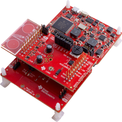
ULP Sense BoosterPack
The Ultra-Low Power (ULP) Sense BoosterPack™ kit is an easy-to-use plug-in module equipped with low power sensors to be controlled by the CC13xx/CC26xx Sensor Controller for ultra-low power sensing. By combining the BoosterPack with any of the CC13xx/CC26xx LaunchPads, development and evalutation of ultra-low power sensing applications is made easy.
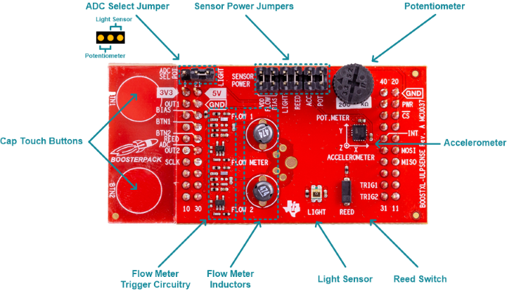
The ULP Sense BoosterPack features the following sensors:
- Analog Light Sensor
- Capacitive Touch Buttons
- LC Flow Meter
- Potentiometer
- Reed Switch
- SPI Accelerometer
Unused sensors can be disabled to save current consumption by removing jumpers. In addition, power for used sensors can be controlled dynamically by the Sensor Controller by controlling a GPIO.
For more information, refer to the ULP Sense BoosterPack User's Guide.
EnergyTrace
EnergyTrace™ technology is a power analyzer tool for CCS that measures the application’s current consumption. The tool can be used stand-alone as a power profiling tool, or in EnergyTrace++ mode within a debug session for code analysis to help optimize the application for ultra-low-power consumption.
EnergyTrace does not replace a lab grade power analyzer
EnergyTrace is not meant as a replacement for power analyzers. EnergyTrace should only be used as a tool to quickly observe current profiles of certain applications and verify certain power modes.
Use a power analyzer for accurate measurements of current consumption for any applications.
EnergyTrace mode (without the "++") is the base of EnergyTrace Technology and enables analog energy measurement to determine the energy consumption of an application but does not correlate it to internal device information.
EnergyTrace mode is available on all CC13xx and CC26xx LaunchPads. Refer to the EnergyTrace User Guide section in any of the SimpleLink SDK Components User's Guide for how to use EnergyTrace with CC13xx and CC26xx devices.
LC Flow Metering
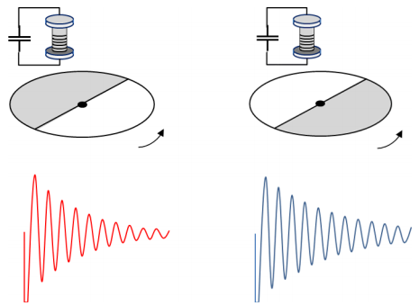
Inductive sensing is a technique for non-contant detection of metal objects. LC inductive sensing uses an LC sensor for detecting metal objects. The LC sensor consists of an inductor and a capacitor.
First, the capacitor is charged by a short pulse, then the LC sensor starts oscillating and the signal voltage level decays. The frequency and decay rate of the oscillations varies by the inductor and capacitor used, as well as the ambient environment like temperature and humidity.
When there is a metal approaching the oscillating LC, the signal decays faster due to the energy absorption by eddy current of the metal part. As shown in the figure below, the LC sensor is used to identify metal (signal in red) or non-metal part (signal in blue).
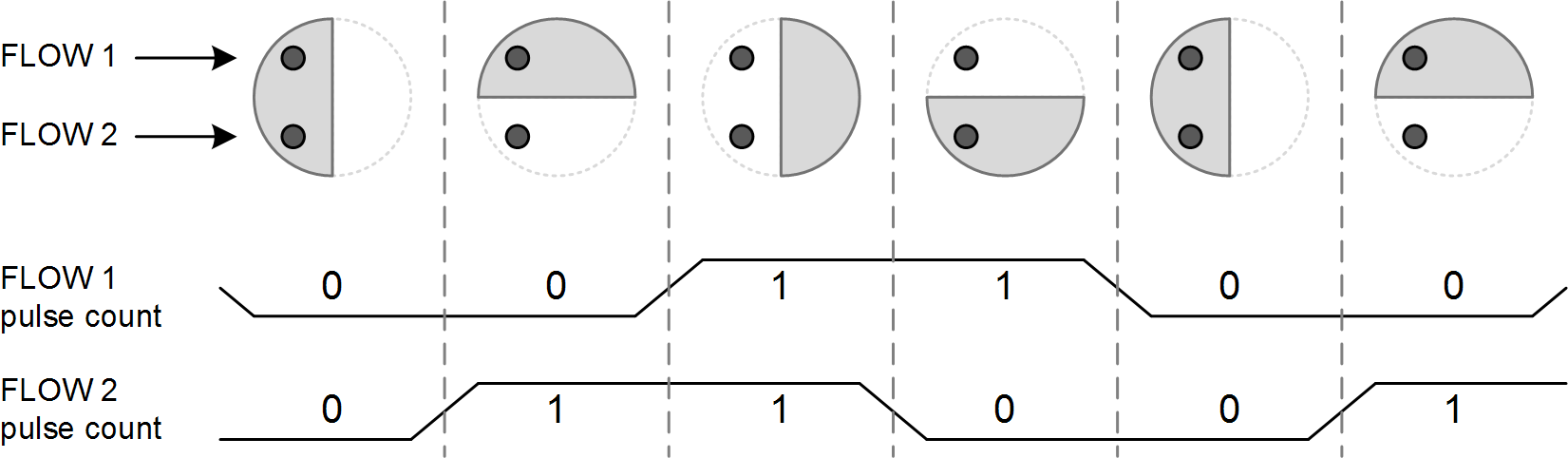
A disc is connected to some stream of flow, and the rotation of that disc is proportional to the rate of flow. The disc is made out of two semicircles: one semicircle made out of metal and the other semicircle made out of non-metal. Note that the non-metal semicircle can even be air.
Two separate LC sensors are used for the detection of both clockwise and counterclockwise rotation of the disc. A logic low is output when the sensor detects the metal part, and a logic high is output when the sensor detects the non-metal part.
The two sensors are placed 90° relative to each other under the rotating disc. Therefore, the signal of a sensor is always 90° out of phase to the other sensor. When the disc rotates, the measurements produce a 2-bit gray-code, where each code corresponds to one quadrant of a full rotation.
The figure below shows a clockwise rotation of a disc. The grayed out semicircle on the disc is made out of metal.
For more details on LC Flow Metering, refer to LC Sensor Rotation Detection with Extended Scan Interface (ESI).
Task 1 – Test the Sensor Controller Example
When developing any application with the Sensor Controller, the starting point should almost always be Sensor Controller Studio. Sensor Controller Studio contains examples which demonstrates how to use the different peripherals and resources available on the Sensor Controller.
For the ULP Sense BoosterPack, there are examples for each of the sensors in Sensor Controller Studio. Each example demonstrates how to interact with the sensor, as well as providing example usage of said sensor.
Feel free to modify the examples
All examples in Sensor Controller Studio, including the examples for the ULP Sense BoosterPack, can always be restored to the original. Simply open a new instance of the example from the Start Page to restore it.
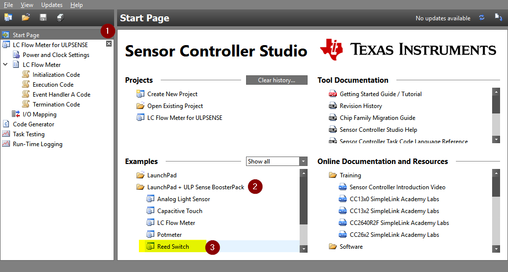
Open the Sensor Controller Example
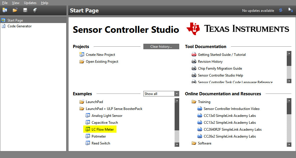
For this task the LC Flow Meter example will be used. Open Sensor Controller
Studio and navigate to the Start Page. The ULP Sense BoosterPack examples can
be found in the Examples window, under the LaunchPad + ULP Sense BoosterPack
folder. Expand that folder, and open the LC Flow Meter example.
When opening the example, make sure to select the correct Target chip name which matches the LaunchPad you are using. This can later be changed in the Sensor Controller Project Page if needed.
Example Preparations
With the ULP Sense BoosterPack example opened, you should now be viewing the Sensor Controller Project Page. The project description describes in high-level detail what the example does, and any required hardware setup.
As described in the project description for the LC Flow Meter example, the
following hardware setup is required:
- On the LaunchPad, remove the TDI and TDO jumpers between the chip and the debugger.
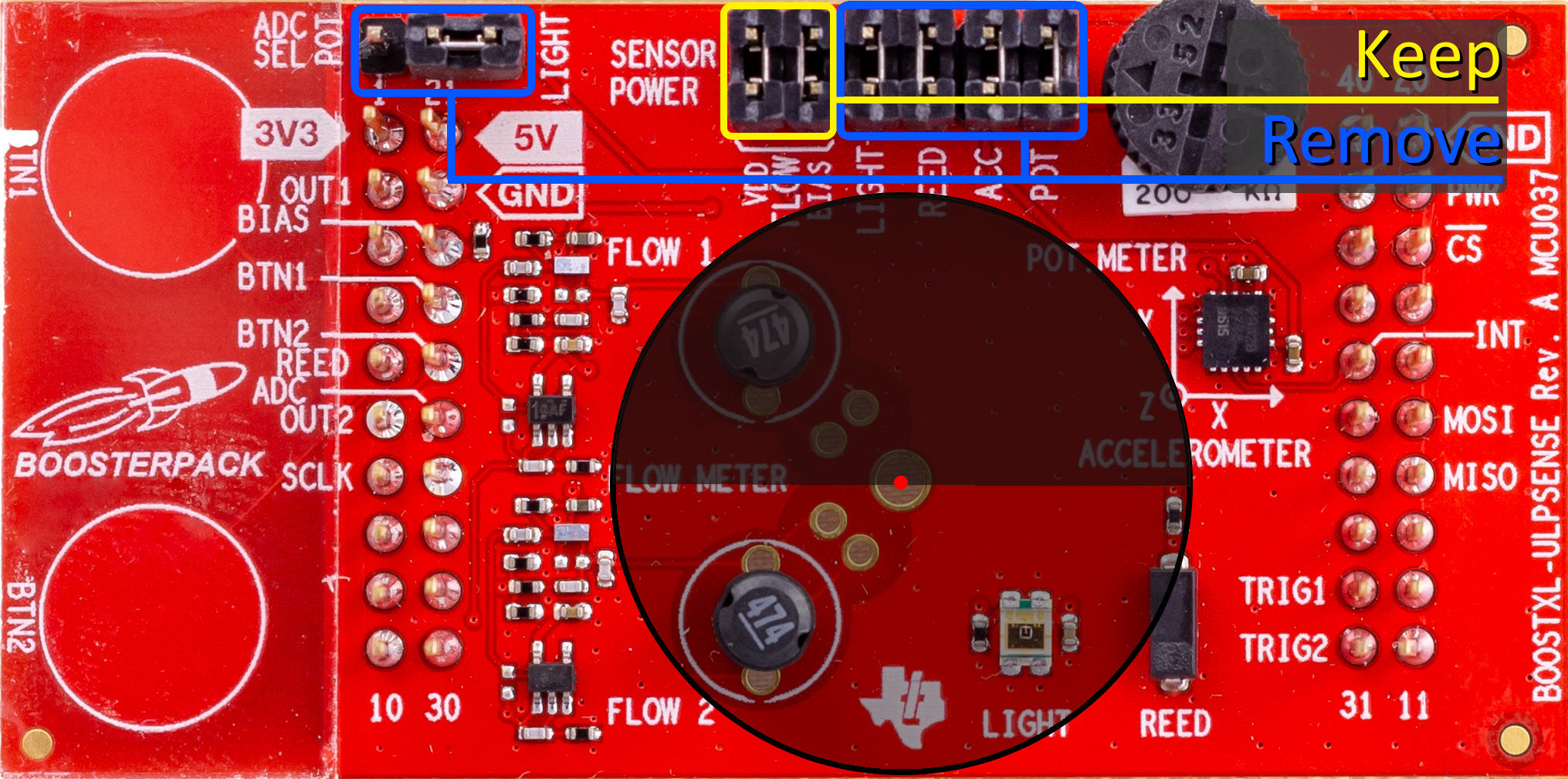
- On the ULP Sense BoosterPack, mount jumpers on FLOW VDD and FLOW BIAS. Remove all other jumpers.
Prepare the meter disc used for the flow meter sensing.
- The disc should be composed of two semicircles: one semicircles made from (or plated with) metal, and the other semicircles with a non-metal plating. Note that stainless steel works better than copper, which in turn works better than aluminum.
- The disc must have a minimum diameter which covers both inductors.
- The disc must be placed over the center hole on the ULP Sense BoosterPack, and around 2-3 mm above the inductors.
- Ensure the rotation axle is stable, and that the disc does not vibrate.
Important setup
Make sure that the meter disc is large enough and properly placed. The disc must be centered on the ULP Sense BoosterPack, properly spaced from the inductors, and the rotation axle stable.
The picture below shows how and where the disc should be placed, as well as which jumpers should be removed and which should be kept.
Get to know the Example
With the preparations done, it is time to review what the example does and how it works. The project description already provides a high-level description, while the task description provides an in-depth explanation of what the Sensor Controller task actually does. Take your time to review both the project description and the task description.
Quiz
Which statement(s) are true about the LC Flow Meter example?
Test with Run-time Logging
All of the ULP Sense BoosterPack examples support run-time logging, which allows you to quickly evaluate and optimize performance of Sensor Controller tasks. With run-time logging, the tasks are running at full speed on a CC13xx/CC26xx device.
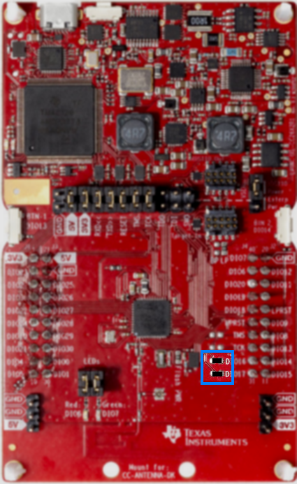
Before starting any run-time logging session, it is important the following jumpers on the LaunchPad between the device and the debugger is mounted:
- 3V3, RXD, TXD, RESET, TMS and TCK
Back and forth
If you are going back and forth from EnergyTrace and testing with run-time logging, then remember to mount the necessary jumpers.
Do the following steps:
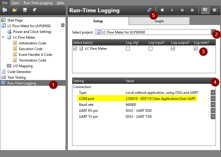
- Navigate to the Run-Time Logging page.
- Select the example project, if not already selected.
- Enable which task data structures should be logged. Some data structures should already be selected by default, as configured by the example.
Configure the connection settings.
- Verify that the COM port corresponds to your device's Application/User UART port.
- Baud rate set to
460800.
When all settings look good, connect to the device.
- If you have multiple devices connected, a popup appears. Simply select the serial number which corresponds to your device and click Select.
I'm unable to start the run-time logging session
Double check the connection with the device is OK, the COM port in the connection settings is correct, and that you selected the correct serial number if multiple devices are connected. If everything looks OK, try connecting again.
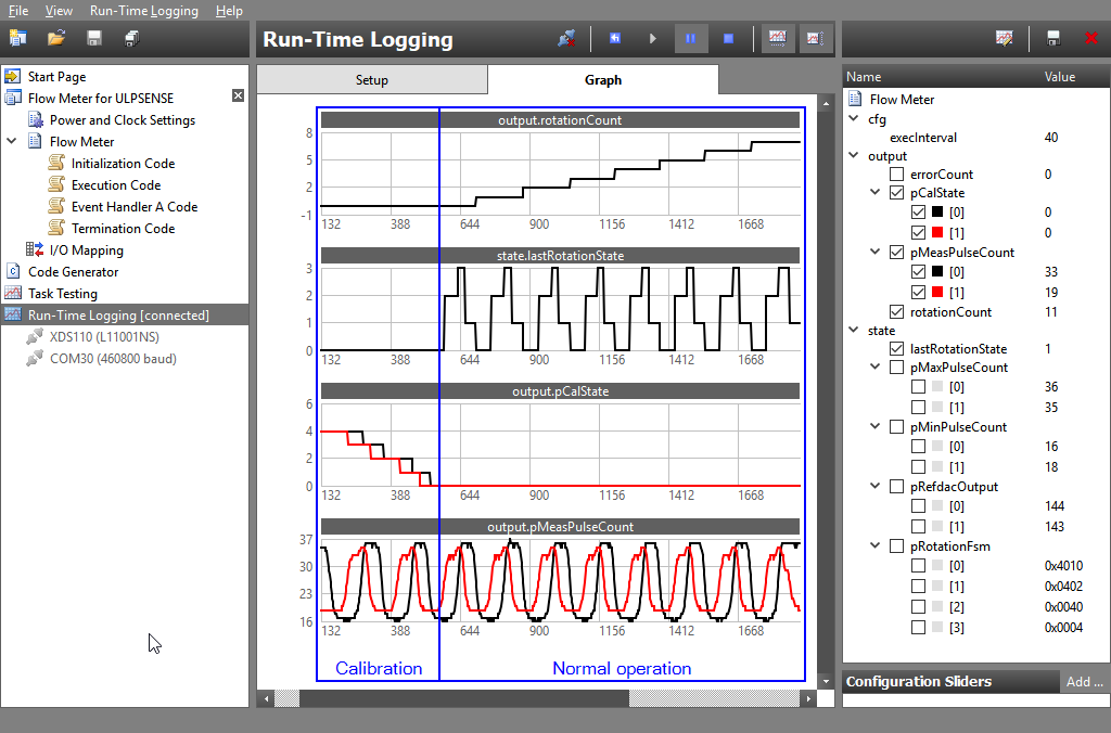
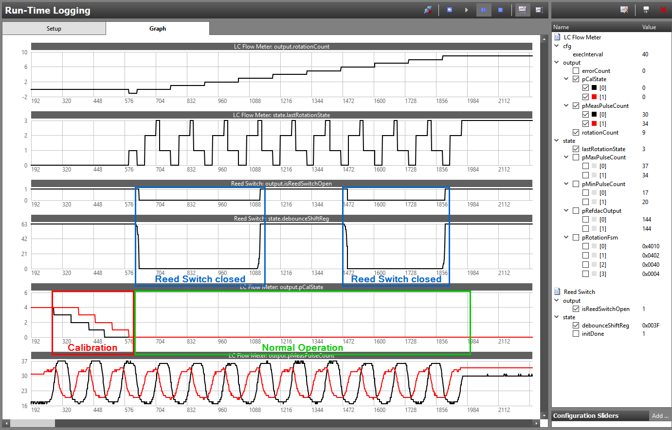
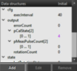
If done correctly, a run-time logging session is now active. You should be in the Graph panel, with four different graphs present. See in the table below for a description for each graph.
| Graph | Description |
|---|---|
output.rotationCount |
Current rotation count. Increments clockwise, decrements anticlockwise. |
state.lastRotationState |
The last rotation state, where bit N maps to channel N. Bit value 1 for metal and value 0 for non-metal. |
output.pCalState |
Calibration state for each channel. Value 0 indicates a channel is calibrated. |
output.pMeasPulseCount |
Measured pulse count for each channel. |
Run-time logging can be started by either clicking the start button, or pressing F5. When running, the flow meter disc can now be rotated.
At first, the Sensor Controller task performs an automatic calibration of each
channel. The disc has to be rotated for the calibration to complete. Only when
both channels are calibrated, that is output.pCalState is 0 for both
channels, will the rotation measurement start. For more information on why and
how the calibration is done, refer to the LC Flow Meter task description.
When each channel is calibrated, you should observe the rotation count being incremented or decremented for each rotation. See the figure below for a complete view of a run-time logging session with both calibration and normal operation.
Great job!
You have successfully opened and tested a ULP Sense BoosterPack example with Sensor Controller Studio. Feel free to test the other ULP Sense BoosterPack examples available if you want to.
Task 2 – Create a Low‐Power Application
After having tested the ULP Sense BoosterPack example and verified the sensors work, the next step is to integrate the example into a fully fledged standalone application. However, some additional steps are required to make sure the resulting application is low-power.
There is an important prerequisite for all applications that integrates a Sensor Controller project and aims to be low-power: Integrating a Sensor Controller project into an application does not make the application low-power. What this means is that an application must be low-power before integrating the Sensor Controller project in order to be low-power after the integration.
Be familiarized with Sensor Controller integration
How to integrate a Sensor Controller project into an application is already covered in the SimpleLink Academy lab Sensor Controller – Project from Scratch. If you haven't done the lab already, do it now and come back afterwards.
Setup Application Project
The starting point when integrating a Sensor Controller project should always
be an existing application project. For this lab the Empty project from the
SDK will be used. However, you can use any existing project, as long as the
project is low-power.
Start by importing a fresh copy of the Empty project from the SDK into CCS.
Refer to Task 1 in Project from Scratch for steps on how
to import the project.
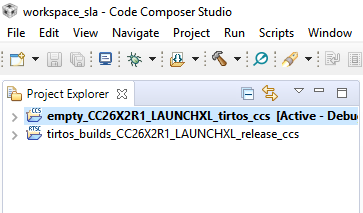
You should now have a project in the Project Explorer view in CCS, either the
Empty project or your own custom project.
Now is a good time to verify the application is low-power before the Sensor Controller project is integrated. Either use a power analyzer or EnergyTrace. Refer to EnergyTrace Instructions for CCS for steps on how to use EnergyTrace.
Power and Clock Settings
A new feature in Sensor Controller Studio with the CC13xx and CC26xx devices is the introduction of Power and Clock Settings. The Sensor Controller Engine on the CC13xx and CC26xx devices supports a 2 MHz clock configuration in addition to 24 MHz, compared to the only clock configuration of 24 MHz on CC13x0 and CC26x0 devices.
It is this 2 MHz clock configuration, also called low-power mode, which enables CC13xx and CC26xx devices to utilize ultra low-power sensing with the Sensor Controller.
CC13xx and CC26xx only
Keep in mind that Power and Clock Settings are only supported for CC13xx and CC26xx devices. You must select a CC13xx or CC26xx target chip in order to view the Power and Clock Settings panel in Sensor Controller Studio.
Next step is to configure the power and clock Settings for the Sensor Controller project. Navigate to the Power and Clock Settings view.
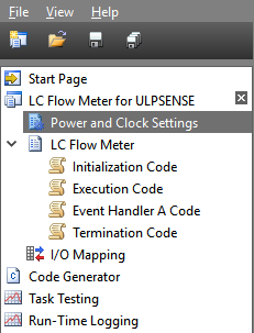
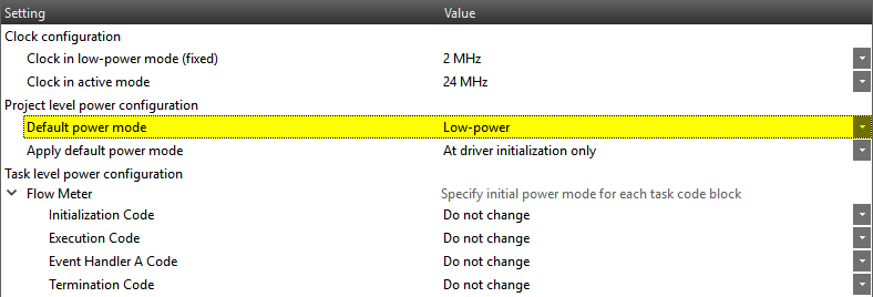
In the Power and Clock Settings panel you are presented with a set of configurations. The clock configuration for both active and low-power mode can be configured, and both project level and task level power can be configured. Project level power configuration sets the default power mode for all task codes and when it applies. Task level power configuration allows for a more fine-grained configuration of power modes for each task code block.
For a new Sensor Controller project, the default configuration is Default
power mode set to Active and Task level power configuration set to Do
not change. However, the ULP Sense BoosterPack examples are already
preconfigured to be the lowest possible power mode. Therefore, no additional
configuration is needed when using the ULP Sense BoosterPack examples.
The easiest way to configure the Sensor Controller project with low-power mode
is to set the Default power mode to Low-power, and leave the Task level
power configuration as Do not change.
Unavailable task resources in low-power mode
Be aware that some task resources are not available during low-power mode. See the Power and Clock Settings Panel documentation in Sensor Contoller Studio for an overview.
Export the Sensor Controller Project
Next step is to setup the Sensor Controller Project in the CCS project and export the Sensor Controller Interface (SCIF) Driver.
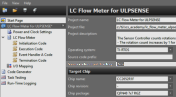
Navigate to the Project Panel in Sensor Controller Studio and rename the
Source code output directory to something more descriptive. The directory
will be named ./scs in this lab. It is important that the relative path
./* is used.
After renaming the output directory, click File → Save Project As...
and save the Sensor Controller project in the CCS project folder with the name
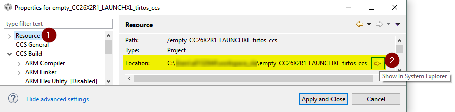
lc_flow_meter.scp. You can find the location of your CCS project by going
back to CCS, open project properties of your project (Alt+Enter)
and go to the Resource tab.
Navigate to the Code Generator panel in Sensor Controller Studio. If Output
automatically is not checked, click the Output SCIF driver files button to
trigger code generation.
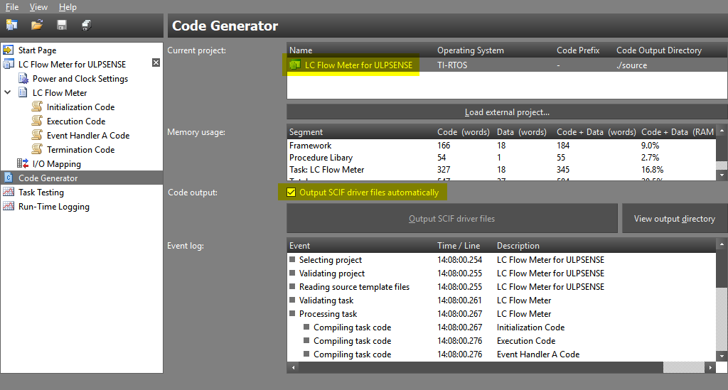
If you now click the View output directory you should be directed to the
output directory folder in the CCS project.
In Project Explorer, your CCS project should now contain both the Sensor Controller project as well as an additional folder which contains the generated source code.
Build the CCS project and verify it compiles successfully.
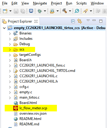
Since we specified the output directory with the relative path ./*, the
outputted source code from the Sensor Controller project will be placed in the
CCS project workspace and automatically built when compiling the CCS project.
Efficient setup for Sensor Controller development
This setup with the Sensor Controller project allows for very efficient development. Now, anytime you do changes to your Sensor Controller project, simply open up the Code Generator panel and trigger a new code generation. Then, go back to CCS and compile as normal.
Make a Low-Power Application
With the Sensor Controller project exported and generated code available in the CCS project, the next step is to integrate the Sensor Controller project.
This section focuses on how one should interface the Sensor Controller project from an application's stand point of view in order to maintain low-power performance. Whether the Sensor Controller project is an ULP Sense BoosterPack example or any other Sensor Controller project does not matter. The methodology is the same.
The specification for the flow meter toy application used in this sections is the following:
- Unmodified LC Flow Meter example running on the Sensor Controller.
- Application is alerted by the LC Flow Meter example each time the rotation count or the error count changes.
- Application processes each alert from the Sensor Controller.
- The red LED is blinked three times if the error count changed.
- Else, the green LED is blinked three times.
- When idle, the application goes into standby.
SCIF Methodology
Two signals are triggered by the Sensor Controller: the Control Ready signal and the Task Alert signal.
| Signal | Description |
|---|---|
| Control Ready | Sensor Controller signals System CPU that a task control operation can be initiated, such as starting and stopping Sensor Controller tasks. |
| Task Alert | Allows the Sensor Controller to wake up the System CPU. Comes with information about which tasks need attention. |
Each signal can be mapped to an application defined callback. The Control Ready signal is optional and does not require to be handled; however, the Task Alert signal must be handled for any meaningful communication between the Sensor Controller and the System CPU.
In the application, when either the Control Ready or Task Alert callback is triggered, the callback's entire purpose should ideally be to signal the application that the corresponding signal occured. The means of signalling is up to the application; you can eiher use SYS/BIOS events to signal Tasks, or use some other established message queue construct if already present in the application.
Of course, the callback can do all sorts of computing. But, try to keep the amount of code in the callback to a minimum. On the other end of the callback should be some variation of the applications event loop or message queue handler.
Creating the Toy Application
Copy the code snippet below and replace the contents of the empty.c file.
If you are using a custom application, then only some slight modifications are required. The two event defines need to be aligned with the applications existing events. The two callbacks needs to post to the correct event handle if SYS/BIOS events are used, or use the existing message queue construct if present. And lastly, the provided application event loop must be replaced by the appropriate event loop.
Read the comments
The following code snippet provides detailed comments explaining the structure of the code and why certain operations are done in a certain order.
/* Standard library header files */
#include <stdint.h>
#include <stddef.h>
#include <stdbool.h>
#include <string.h>

/* TI-RTOS header files */
#include <ti/sysbios/BIOS.h>
#include <ti/sysbios/knl/Event.h>

/* Driver header files */
#include <ti/drivers/GPIO.h>

/* Board header file */
#include "Board.h"

/* Sensor Controller Interface header file */
#include "scs/scif.h"

/* Bit vector macro */
#define BV(x)                 (1 << (x))

/* Application events */
#define APPEV_NONE            Event_Id_NONE

#define APPEV_SC_CTRL_READY   Event_Id_00
#define APPEV_SC_TASK_ALERT   Event_Id_01

#define APPEV_ALL             (APPEV_SC_CTRL_READY | \
                               APPEV_SC_TASK_ALERT)

/* Application event object */
static Event_Struct appEventObj;
static Event_Handle appEventHandle;

/*
 * Struct which contains all relevant data from the Sensor Controller
 * task. Also used to store internal states between task alerts.
 */
typedef struct {
    struct {
        uint16_t old;
        uint16_t new;
    } rotationCount;
    struct {
        uint16_t old;
        uint16_t new;
    } errorCount;
} ScLcFlowMeter;

static ScLcFlowMeter scLcFlowMeter;

/* Sensor Controller Ctrl Ready callback */
static void scCtrlReadyCallback(void)
{
    /*
     * Do as little processing as possible, simply
     * signal the main task.
     */
    Event_post(appEventHandle, APPEV_SC_CTRL_READY);
}

/* Sensor Controller Task Alert callback */
static void scTaskAlertCallback(void)
{
    /*
     * Do as little processing as possible, simply
     * signal the main task.
     */
    Event_post(appEventHandle, APPEV_SC_TASK_ALERT);
}

/* Initialize Sensor Controller project */
static void scInitialize(void)
{
    /* Initialize the Sensor Controller */
    scifOsalInit();
    scifOsalRegisterCtrlReadyCallback(scCtrlReadyCallback);
    scifOsalRegisterTaskAlertCallback(scTaskAlertCallback);
    scifInit(&scifDriverSetup);

    /* Initialize application variables */
    memset(&scLcFlowMeter, 0, sizeof(scLcFlowMeter));

    /* Start Sensor Controller task */
    scifStartTasksNbl(BV(SCIF_LC_FLOW_METER_TASK_ID));
}

/* Read and write any Sensor Controller task data for LC Flow Meter task */
static void scPreProcessLcFlowMeter(void)
{
    /* Fetch and store the new counts for both rotation and error */
    scLcFlowMeter.rotationCount.new = scifTaskData.lcFlowMeter.output.rotationCount;
    scLcFlowMeter.errorCount.new = scifTaskData.lcFlowMeter.output.errorCount;
}

/* Process new Sensor Controller data from LC Flow Meter task */
static void scPostProcessLcFlowMeter(void)
{
    /* Only process if a change was made */
    bool rotationCountChanged = (scLcFlowMeter.rotationCount.new != scLcFlowMeter.rotationCount.old);
    bool errorCountChanged = (scLcFlowMeter.errorCount.new != scLcFlowMeter.errorCount.old);
    if (rotationCountChanged || errorCountChanged) {
        /*
         * Select the red LED if an error was detected,
         * else select the green LED
         */
        uint8_t ledPin = (errorCountChanged)
                       ? Board_GPIO_RLED  /* Red LED */
                       : Board_GPIO_GLED; /* Green LED */

        /* Blink the selected LED 3 times */
        int i;
        volatile int x;
        for (i = 0; i < 3; ++i) {
            /* Simulate processor usage by busy looping */
            for (x = 0; x < 80000; ++x);
            GPIO_write(ledPin, Board_GPIO_LED_ON);

            for (x = 0; x < 80000; ++x);
            GPIO_write(ledPin, Board_GPIO_LED_OFF);
        }
    }

    /* Update the old counts */
    scLcFlowMeter.rotationCount.old = scLcFlowMeter.rotationCount.new;
    scLcFlowMeter.errorCount.old = scLcFlowMeter.errorCount.new;
}

/* Process Sensor Controller task alert */
static void scProcessTaskAlert(void)
{
    /*
     * Clear the ALERT interrupt source. Do this as soon
     * as possible, as it takes some time between clearing the
     * alert interrupt source and acknowledging alert events.
     */
    scifClearAlertIntSource();

    /*
     * See which tasks triggered ALERT events. A bit vector
     * of tasks with an ALERT event is returned.
     */
    uint32_t bvAlertEvents = scifGetAlertEvents();

    /*
     * Any read and write operations to Sensor Controller task
     * data must be done before acknowledging the ALERT event.
     */

    if (bvAlertEvents & BV(SCIF_LC_FLOW_METER_TASK_ID)) {
        scPreProcessLcFlowMeter();
    }

    /*
     * Note that multiple pre-processing could be done here if
     * there were multiple Sensor Controller tasks.
     */

    /*
     * ALERT events should be acknowledged as soon as any
     * access to Sensor Controller task data is finished.
     * Sensor Controller task data should NOT
     * be accessed after acknowledging ALERT events.
     */
    scifAckAlertEvents();

    /*
     * Application processing which require any computational overhead
     * should be done after the ALERT event has been acknowledged
     */

    if (bvAlertEvents & BV(SCIF_LC_FLOW_METER_TASK_ID)) {
        scPostProcessLcFlowMeter();
    }

    /*
     * Same applies for post-processing if there were multiple
     * Sensor Controller tasks.
     */
}

/* Main thread called after starting TI-RTOS */
void *mainThread(void *arg0)
{
    /* Initialize TI-RTOS objects */
    Event_construct(&appEventObj, NULL);
    appEventHandle = Event_handle(&appEventObj);

    /* Call TI drivers init functions */
    GPIO_init();

    /* Configure the LED pins */
    GPIO_setConfig(Board_GPIO_RLED, GPIO_CFG_OUT_STD | GPIO_CFG_OUT_LOW);
    GPIO_setConfig(Board_GPIO_GLED, GPIO_CFG_OUT_STD | GPIO_CFG_OUT_LOW);

    /* Turn off both LEDs */
    GPIO_write(Board_GPIO_RLED, Board_GPIO_LED_OFF);
    GPIO_write(Board_GPIO_GLED, Board_GPIO_LED_OFF);

    /* Initialize the Sensor Controller project */
    scInitialize();

    /*
     * Application event loop. This could be any other equivalent
     * event loop in any other application, as long as the
     * Sensor Controller events are pended.
     */
    while (1) {
        /* Block forever until application events occurs */
        UInt events = Event_pend(appEventHandle,
                                 APPEV_NONE, /* and-mask */
                                 APPEV_ALL,  /* or-mask */
                                 BIOS_WAIT_FOREVER);

        if (events & APPEV_SC_TASK_ALERT) {
            scProcessTaskAlert();
        }
        /*
         * Note that APPEV_SC_CTRL_READY is simply ignored.
         * It is optional to handle this event and it is
         * up to the application.
         */
    }
}
empty.c: Integrated Sensor Controller project
Take some time to study the provided code snippet. It is important that you understand how to correctly interface the Sensor Controller in order to remain low-power.
Quiz
Is it advised for the application to access Sensor Controller task data
(scifTaskData) after having acknowledged the task alert
(scifAckAlertEvents())?
What is the best way for the application to receive an alert event from a Sensor Controller task?
EnergyTrace Observation
Compile the CCS project and verify the application successfully compiles. After finishing compiling, flash your device and setup the flow meter disc. Start spinning the disc and you should see the green LED blink three times when a full rotation is made.
You might sometimes see the red LED blink instead of the green LED if an invalid transition state was measured. This can happen if the disc either moves too much off-center, or spins too quickly for the Sensor Controller to keep up.
It is time to take a look at the power profile of the application with the LC Flow Meter task integrated. Connect the device to EnergyTrace and perform a measurement with at least one rotation captured. Again, refer to EnergyTrace Instructions for CCS for steps on how to use EnergyTrace.
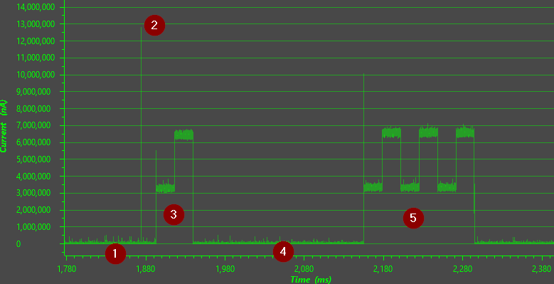
When done correctly, you should observe a power profile somewhere along the lines of the figure below.
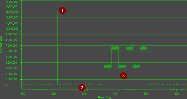
The figure gives a power profile overview of the application. The numbers indicate the following:
- Recharge pulse to maintain VDDR level.
- Sensor Controller task running while the application is in standby.
- Application code running, processing the Sensor Controller task alert and blinking the LED three times. Note that the Sensor Controller task continues to run in the background after the task alert is acknowledged.
High power consumption for application
Keep in mind the application is busy looping while blinking the LED, which explains the high current consumption. This is only done to easier show the contrast of power consumption of both the System CPU and the LED compared to the Sensor Controller.
Zooming closer to the event where the System CPU is woken up by the Sensor Controller, it is much easier to observe where the Sensor Controller task is running. In addition, it is quite clear the contrast in power consumption between the Sensor Controller and the System CPU.
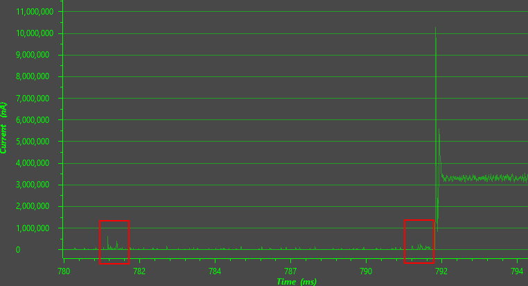
The red boxes are the LC Flow Meter task waking up and performing a measurement. Each red box represents a full execution of the Event Handler code in the LC Flow Meter task.
The second red box is where the task registers a change in the roation count or the error count, and subsequently signals a task alert to the System CPU. Since the System CPU is in standby when the task alert occurs, the Sensor Controller wakes up the System CPU.
Look at the difference!
Even though EnergyTrace is not a tool for properly measuring power consumption, it should still be easy to see the difference of power consumption between the Sensor Controller and the System CPU.
You can imagine how much more the power consumption would be if the System CPU would have to wake up as often as the Sensor Controller does to perform the same kind of measurements.
Task 3 – Modify and Develop a Custom Application
After having integrated the ULP Sense BoosterPack example with the application and verified the low-power capabilities of the Sensor Controller with EnergyTrace, the final step is to modify the Sensor Controller project to fit your custom application.
What kind of modifications required depends entirely on the specifications for your custom application. But, with the foundation set by Task 2, the methodology is the same regardless of any custom application.
Custom Application Specification
For this section the following custom application is to be implemented:
- Two tasks run on the Sensor Controller.
- LC Flow Meter, which runs on a dynamic sampling frequency.
- Reed Switch, which is periodically polled with a static period.
- The sampling frequency of LC Flow Meter is controlled by the reed Switch.
- Reed Switch is active high.
- Sampling frequency set to 100 Hz when the reed Switch is inactive.
- Sampling frequency set to 20 Hz when the reed Switch is active.
- The application is in standby until a task alert occurs.
- If a new rotation count or error count is measured, a single RF packet is transmitted on the air.
- If the Reed Switch goes from active to inactive, or vice versa, change the sampling frequency for the LC Flow Meter task.
Reed Switch Integration
We will reuse and expand on the Sensor Controller project used in the previous task. The first step will be to open up the Reed Switch example in Sensor Controller Studio and test it out. Again, the example can be found in the Start Page in Sensor Controller Studio.
Open up the example and verify that the sensor and example works as intended. Note that you need a magnet for the Reed Switch. Go back to Task 1 if you need a refresher for how to test the example.
In order to interface multiple Sensor Controller tasks from the application, both the LC Flow Meter task and the Reed Switch task must be part of the same Sensor Controller project. Therefore, copy the Reed Switch task from the Reed Switch project into the LC Flow Meter project.
To copy the existing Reed Switch task, go to the Project Page of LC Flow
Meter. At the Sensor Controller Tasks overview, click Copy
existing.... In the popup, navigate to the previously opened Reed Switch
project. The project file path for the Reed Switch project is found under its
Project page. Select the reed_switch_ulpsense.scp project file and click
Open. In the new popup, select the Reed Switch task and click
Select.
Some slight modifications in the Reed Switch task are required, as there is a pin conflict between the two tasks. Both tasks defines a digital pin which is used to power the ULP Sense BoosterPack. However, in order for the tasks to share the pin, both must declare it as the same kind of GPIO pin. This is not the case.
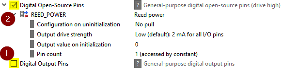
The LC Flow Meter task defines the power pin as digital open-source while the Reed Switch task defines the power pin as digital output. To fix this, both tasks must define the power pin to be either digital open-source or digital output. For simplicity sake, the Reed Switch should redefine the power pin to be digital open-source.
Go to the Reed Swich task page, disable the Digital Output Pin resource,
enable the Digital Open-Source Pins resource, and call the new pin
REED_POWER. Use the default settings.
Since the old power pin was removed and a new was created, the I/O mapping of the Sensor Controller project must be fixed. Go to the I/O Mapping Page and make sure both power pins of the LC Flow Meter and Reed Switch task is set to the same pin. Both pins should now be marked with a yellow color if done correctly.
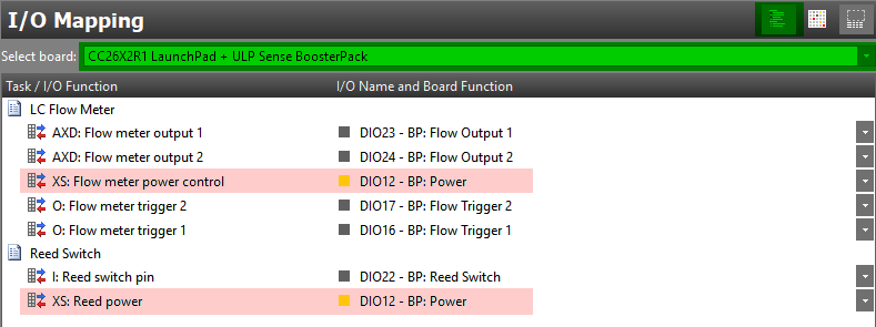
DIO numbers may vary
If you are using a different board than the CC26x2R1 LaunchPad, then the DIO numbers shown your I/O Mapping Page may vary from what is shown above.
The Reed Switch power pin must also be renamed to the new name in the task
code. Go to the Execution Code Page in the Reed Switch task and rename the
AUXIO_O_REED_POWER to AUXIO_XS_REED_POWER.
Lastly, since the power pin was changed from a digital output to a digital open-source pin in the Reed Switch task, the Reed Switch digital input pin now floats when the power pin is turned off. To avoid this, the input pin must be manually enabled after the power pin is turned on and disabled after the power is turned off.
Go to the Initialization Code Page in the Reed Switch task and do the follow changes:
gpioDisableInputBuf(AUXIO_I_REED_SWITCH); // <== Add this

// Schedule the first execution
fwScheduleTask(1);
Reed Switch: Initialization Code
Go to the Execution Code Page in the Reed Switch task and do the follow changes:
// Enable power for the pull-up resistor, and give it time to take effect
gpioSetOutput(AUXIO_XS_REED_POWER); // AUXIO_O_REED_SWITCH ==> AUXIO_XS_REED_POWER
gpioEnableInputBuf(AUXIO_I_REED_SWITCH); // <== Add this
fwDelayUs(10);

// ... code omitted ...

// Disable power for the pull-up resistor
gpioClearOutput(AUXIO_XS_REED_POWER); // AUXIO_O_REED_SWITCH ==> AUXIO_XS_REED_POWER
gpioDisableInputBuf(AUXIO_I_REED_SWITCH); // <== Add this
Reed Switch: Execution Code
And that should be it. Go to the Code Generation Page, trigger an another code generation and verify the application still compiles successfully.
Save your work
Feel free to save the Sensor Controller project at this point.
Multiple Tasks Testing
To verify that both tasks works concurrently, go to the Run-Time Logging Page.
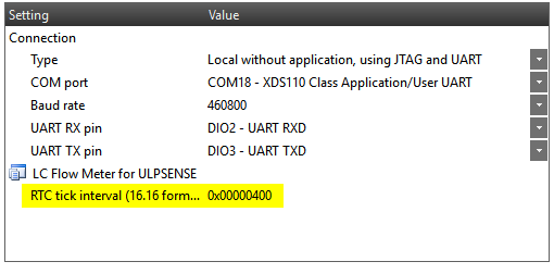
Before starting the Run-Time Logging session, configure the RTC tick interval
to 64 Hz, which equals to 0x400. This is because the Reed Switch task uses RTC scheduling, and
therefore the RTC tick must be configured.
Run-time logging only
Note that the RTC tick interval configuration is only for this particular run-time logging session. This does not configure the RTC tick interval for the application.
After the RTC tick interval has been configured, start the run-time logging session. Run the LC flow meter disc while placing a magnet close the reed switch.
Cramped space
Be aware that the reed switch is placed very close to the where the LC flow meter disc is rotating. Since the disc is covered in half-metal, try to approach the reed switch from the side to avoid getting too close to the disc.
If done correctly, you should observe in the run-time logging session that both the LC Flow Meter task and the Reed Switch task are runnning concurrently without interferring with eachother.
Sensor Controller Development Cycle
After the Reed Switch task is integrated into the Sensor Controller project and a new code generation is triggered successfully, the next step is to modify the application to accomodate for the new task and implement the additional logic.
Expand the box below and copy the code snippets into empty.c where it is
appropriate.
/* Static sample frequency of the Reed Switch task */
#define REED_SWITCH_SAMPLE_HZ          64

/*
 * Fast and slow sample frequencies of the LC FLow Meter task.
 * Fast sample frequency used when Reed Switch is not open,
 * and slow sample frequency used when open.
 */
#define LC_FLOW_METER_FAST_SAMPLE_HZ   100
#define LC_FLOW_METER_SLOW_SAMPLE_HZ   16
empty.c: Sample frequency defines
/*
 * Struct which contains all relevant data from the Reed Switch
 * task. Also used to store internal states between task alerts.
 */
typedef struct {
    struct {
        bool old;
        bool new;
    } isOpen;
} ScReedSwitch;

static ScReedSwitch scReedSwitch;
empty.c: Reed Switch struct typedef
static void scInitialize(void)
{
    /* ... */

    /* Initialize application variables */
    memset(&scLcFlowMeter, 0, sizeof(scLcFlowMeter));
    memset(&scReedSwitch, 0, sizeof(scReedSwitch));

    /* Configure RTC ticks and start now */
    scifStartRtcTicksNow(0x00010000 / REED_SWITCH_SAMPLE_HZ);

    /* Start Sensor Controller task */
    scifStartTasksNbl(BV(SCIF_LC_FLOW_METER_TASK_ID) |
                      BV(SCIF_REED_SWITCH_TASK_ID));
}
empty.c: scInitialize() modifications
/* Read and write any Sensor Controller task data for Reed Switch task */
static void scPreProcessReedSwitch(void)
{
    scReedSwitch.isOpen.new = (scifTaskData.reedSwitch.output.isReedSwitchOpen != 0);

    /*
     * Change the LC Flow Meter sample frequency if
     * the isOpen state changed.
     */
    if (scReedSwitch.isOpen.new != scReedSwitch.isOpen.old) {
        /* Fast sample frequency if open, else slow sample frequency */
        uint16_t newSampleHz = (scReedSwitch.isOpen.new)
                             ? LC_FLOW_METER_FAST_SAMPLE_HZ
                             : LC_FLOW_METER_SLOW_SAMPLE_HZ;

        /*
         * The sampling frequency of LC Flow Meter is determined by the
         * cfg.execInterval data member, and is represented in timer1 ticks.
         * Timer1 runs on a 4.096 kHz clock, which means the resulting
         * ticks for a given sampling frequency is 4096 divided by the
         * sampling frequency.
         */
        scifTaskData.lcFlowMeter.cfg.execInterval = 4096 / newSampleHz;
    }
}
empty.c: scPreProcessReedSwitch() function
/* Process new Sensor Controller data from Reed Switch task */
static void scPostProcessReedSwitch(void)
{
    if (scReedSwitch.isOpen.new != scReedSwitch.isOpen.old) {
        /* Blink the red LED once */
        volatile int x;
        /* Simulate processor usage by busy looping */
        for (x = 0; x < 80000; ++x);
        GPIO_write(Board_GPIO_RLED, Board_GPIO_LED_ON);

        for (x = 0; x < 80000; ++x);
        GPIO_write(Board_GPIO_RLED, Board_GPIO_LED_OFF);

        /* Update the old open state */
        scReedSwitch.isOpen.old = scReedSwitch.isOpen.new;
    }
}
empty.c: scPostProcessReedSwitch() function
static void scProcessTaskAlert(void)
{
    /* ... */

    if (bvAlertEvents & BV(SCIF_LC_FLOW_METER_TASK_ID)) {
        scPreProcessLcFlowMeter();
    }

    if (bvAlertEvents & BV(SCIF_REED_SWITCH_TASK_ID)) {
        scPreProcessReedSwitch();
    }

    /* ... */

    if (bvAlertEvents & BV(SCIF_LC_FLOW_METER_TASK_ID)) {
        scPostProcessLcFlowMeter();
    }

    if (bvAlertEvents & BV(SCIF_REED_SWITCH_TASK_ID)) {
        scPostProcessReedSwitch();
    }

    /* ... */
}
empty.c: scProcessTaskAlert() modifications
Make sure the application compiles successfully after you have made the modifications.
I'm getting compilation errors!
Read the compile errors. Have you remembered to generate code from the Sensor Controller project? Maybe something was erroneously modified in the source code?
Flash the device and setup the flow meter disc. Start rotating the disc, and observe the same three blinks of the green LED on the LaunchPad.
While the disc is rotating, put a magnet close to the reed switch. You should see the red LED blink once each time the reed switch transition from closed to open and vice versa.
Fix the Input Variable
Pay extra attention to the new function scPreProcessReedSwitch(). Whether
the new state of the Reed Switch is open or closed, the sampling frequency of
the LC Flow Meter task is set to either the fast or slow sample frequency,
respectively.
The new sample frequency is set directly in the configuration data member of
the LC Flow Meter task, cfg.execInterval. Next time the LC Flow Meter task
schedules the next execution, the new sampling frequency is used.
Ideally, any input data to a Sensor Controller task should be set in a separate input variable. This way, the Sensor Controller task can asynchronously receive new data in input data members and update any internal data members as it sees appropriate. The Sensor Controller task then has full control on how and when inputted data from the System CPU is handled.
Good practice
Note that you are not required to fix the update of the cfg.execInterval
to be an input variable. The current solution above works as intended.
However, it is best practice to use input variables. In addition, fixing this issue will show you how easy it is to modify the Sensor Controller project and include the modifications into the application.
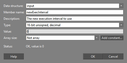
Start by modifying the LC Flow Meter task. In the event handler code, under the Data structures panel, click Add to add a new data structure member.
In the popup, configure the data structure member to input, name it
newExecInterval, let the type be 16-bit unsigned, decimal, and let the
default value be 0. Click Ok.
Then, at the bottom of the event handler code where the next timer1 trigger is scheduled, apply the modifications in the code snippet below.
// Update the execution interval if a new interval is available
if (input.newExecInterval != 0) {
    cfg.execInterval = input.newExecInterval;
    input.newExecInterval = 0;
}

// Schedule the first execution (default = 100 Hz)
evhSetupTimer1Trigger(0, cfg.execInterval, 0);
LC Flow Meter: Event Handler Code modifications
What happens now is that the input.newExecInterval is checked for before the
next timer1 trigger is scheduled. If it is non-zero value, it is assumed to be
the new sampling frequency and cfg.execInterval is updated accordingly.
Note that input.newExecInterval must be cleared to 0 when a new value is
received, as to indicate the input variable has been processed.
And that is it for the Sensor Controller project. As always, go to the Code Generator view and trigger code generation.
Go back to the CCS project and modify the scPreProcessReedSwitch() function
to update the input.newExecInterval instead of the cfg.execInterval data
member.
static void scPreProcessReedSwitch(void)
{
    /* ... */

        scifTaskData.lcFlowMeter.input.newExecInterval = 4096 / newSampleHz;
    }
}
empty.c: scPreProcessReedSwitch() modifications
Build the CCS project and verify the application successfully compiles. Flash the device and setup the flow meter disc. Test that the application still works as intended with both the flow meter disc and the reed switch; the green LED blinks three times for each rotation count, and the red LED blinks once when the reed switch goes from open to closed or vice versa.
Observe Current Consumption
As the final step, use EnergyTrace to observe the current consumption profile of the modifed application and verify it is still low-power. Again, refer to EnergyTrace Instructions for CCS on how to use EnergyTrace.
Perform an EnergyTrace capture while the flow meter disc is rotating as well as the reed switch being opened and closed. If done correctly, you should see some of the following current profile.
- Sensor Controller with both LC Flow Meter and Reed Switch tasks running. The LC Flow Meter task is running at 100 Hz.
- Recharge pulse to maintain VDDR level.
- Application processing task alert from the Reed Switch task.
- Sensor Controller with both LC Flow Meter and Reed Switch tasks running. The LC Flow Meter task is running at 16 Hz.
- Application processing task alert from the LC Flow Meter task.
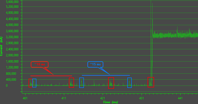
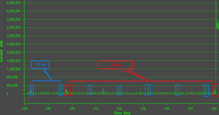
Zooming closer to the event where the System CPU is woken up by the Sensor Controller when the LC Flow Meter task is running at 100 Hz, it should be possible to identify the sample frequencies of both the LC Flow Meter task and the Reed Switch task.
In the Figure below the LC Flow Meter task is outlined in the red boxes, while the Reed Switch task is outlined in the blue boxes. The LC Flow Meter task is sampled at around 100 Hz, which should equal to around 10 ms. The Reed Switch task is sampled at 64 Hz, which should equal to around 15 ms.
Now, zooming closer to the event where the System CPU is woken up by the Sensor Controller when the LC Flow Meter task is running at 16 Hz, it should be possible to identify the sample frequencies of both the LC Flow Meter task and the Reed Switch task. However, now the time between each LC Flow Meter sample should be longer.
In the Figure below the LC Flow Meter task is outlined in the red boxes, while the Reed Switch task is outlined in the blue boxes. The LC Flow Meter task is sampled around around 16 Hz, which should equal to around 62 ms. The Reed Switch task is still sampled at 64 Hz, which should equal to around 15 ms.
It might look like the Sensor Controller is more active between samples than it is. The reason is that the Sensor Controller in low-power mode operates so close to the noise floor, and that EnergyTrace is not capable of capturing so low current at such great resolution.
That, combined with the limitations of EnergyTace's graphing capabilities in CCS, then noise sometimes looks like meaningful measurements while it is not.
Congratulations!
You have now implemented a custom application which uses multiple sensors from the ULP Sensor BoosterPack. You have learned how to setup an efficient development environment for Sensor Controller Studio, and how to use EnergyTrace to verify expected the current profile for your application is as expected.
Hopefully, you have understood the low-power capabilities of the Sensor Controller, as well as how to properly use them in any kind of application.
EnergyTrace Instructions for CCS
This section discusses the necessary steps to use EnergyTrace on a CC13xx or CC26xx LaunchPad in stand-alone-mode in CCS. In stand-alone mode, the debugger is not active and the displayed current consumption is what to expect for the final application.
Prepare the LaunchPad:
- Flash the LaunchPad with the application to be analyzed.
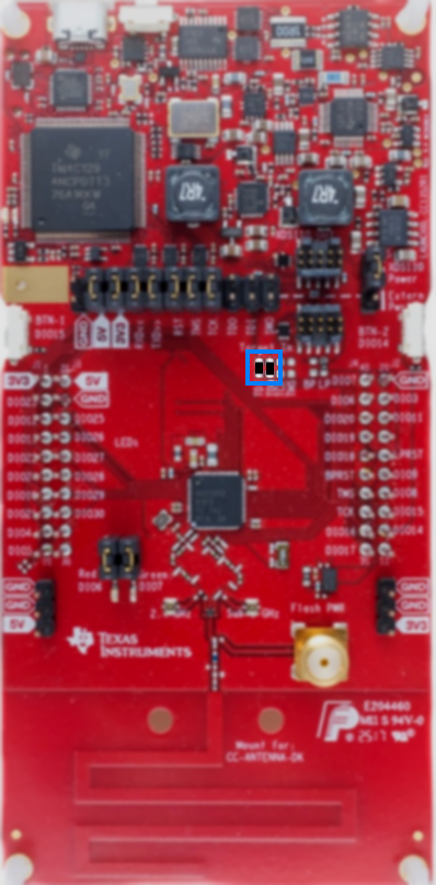
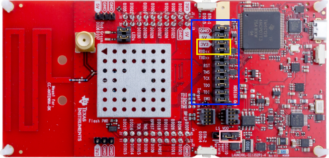
Remove all jumpers on the LaunchPad between the XDS debugger and the device, except for the 3V3 and RXD jumpers. That is, remove all jumpers in the blue box except for the jumpers in the yellow box in the figure below.
- The 3V3 jumper is needed to power the device. Note that the GND jumper is not necessary, as there is no separation on the ground plane on the board.
- The RXD jumper should be mounted, as in most cases the RXD pin is configured to be floating. When this is the case and the jumper is removed, the pin floats and will leak current.
Mount a jumper on the power source selector in the XDS110 Power configuration. See the pink box in the figure below.
- Trigger a recalibration of EnergyTrace by power cycling the LaunchPad. Disconnect and re-connect the micro-USB cable connected to the LaunchPad.
When the LaunchPad is prepared, do the following in CCS:
- EnergyTrace requires some configurations the first time it is being used
within a CCS workspace. Go to the menu
Window→Preferences, and navigate toCode Composer Studio→Advanced Tools→EnergyTrace Technology. Under Target Connection, set Connection to
XDS110and Voltage to3300.0mV. ET-HDR Range Selector must be set toLow current, narrower range higher accuracy. Click Apply and Close to save the preferences.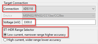
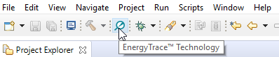
Make sure no debug session is active and click the EnergyTrace Button.
A dialog with instructions on how to use EnergyTrace Stand-alone Measurement Mode will pop-up. Click Proceed to continue.
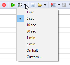
Select how long you want to capture data by clicking the Select Measurement Duration button.
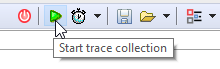
To start capturing data, click the green play button. The red LED on the XDS110 debugger should turn on, and will be turned on for the duration of the EnergyTrace capture.
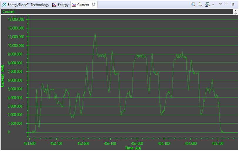
When EnergyTrace is finished capturing data, review the application’s power profile and have a closer look in the current graph. Figure below shows a zoomed-in current graph of BLE advertising.
- You can zoom in on a specific region on the current graph by left clicking and selecting a region.
You can zoom in on a specific area on both the X and Y axis by left clicking and selecting outisde of the axis.
Further Reading
If you want a deeper understanding of the theory behind the LC Flow Metering, read the LC Sensor Rotation Detection With MSP430 Extended Scan Interface (ESI). It goes into details of the working principles of LC sensors, as well as what is required from a software implementation.
For a complete kit of an extended scan interface reference design as well as a flow meter disc, see Water Meter Reference Design for two LC Sensors, Using Extended Scan Interface (ESI).
Abbreviations and Glossary
| Abbreviation | Definition |
|---|---|
| AUX RAM | Sensor Controller Memory |
| BP | BoosterPack |
| CCS | Code Composer Studio |
| LP | LaunchPad |
| SCIF | Sensor Controller Interface |
| SCS | Sensor Controller Studio |
| SDK | Software Development Kit |