Introduction
This tutorial shows how to get started using the TI analog sensors that are both supported by Analog Signal Chain Studio (ASCStudio) and are also available on TI LaunchPads and BoosterPacks.
+
Analog Signal Chain Studio: The ASCStudio product leverages TI's SysConfig tool to enable users to graphically configure one or more sensors and generate 100% portable C "hello world" applications that read data acquired by these sensors. Moreover, all generated sources are modular, fully commented, and standards-based C99.
The cost of this portability is that the generated code isn't 100% complete without the user supplying at least two low-level functions that have no portable implementation: one to delay the MCU for a specified period, and another to transfer data over an I2C bus.
ASCStudio + SimpleLink SDK: However, when ASCStudio is used with a SimpleLink SDK, these non-portable functions are automatically generated by SysConfig. Thus, fully runnable applications that periodically read data from sensors can be created and run in just a few minutes, without writing any code.
Tutorial summary
Despite the length of this tutorial, adding a sensor to an existing SDK project is quite simple:
- Add the ASCStudio product to an existing project (Task 2.3)
- Add and configure a sensor using SysConfig (Task 3.1)
- Build, run, and visualize sensor data (Task 4)
Along the way, you'll also learn how to:
- Install new products (ASCStudio) via TI Resource Explorer (Task 1)
- Add BoosterPack support to projects (Task 2.2)
Prerequisites
To follow the steps of this tutorial, you'll need a TI LaunchPad, a SimpleLink SDK for the device family of the MCU on the LaunchPad, and (if the LaunchPad does not have on-board sensors) one or more sensor BoosterPacks.
Recommended background
This tutorial assumes very little prior knowledge of development using Code Composer Studio (CCS) or SimpleLink SDKs. However, if this is your first time using either of these tools, there are some other documents you'll find helpful.
- SimpleLink Academy: TI Drivers Project Zero (if you've never before used a SimpleLink SDK)
- SimpleLink SDK Quick Start Guide (for information related to applications well suited for the SDK's supported device family)
Hardware requirements
One (or more) of the following LaunchPads:
- CC3235SF LaunchPad (LAUNCHXL-CC3235SF)
- CC3220SF LaunchPad (LAUNCHXL-CC3220SF)
- CC26X2R1 LaunchPad (LAUNCHXL-CC26X2R1)
- CC1352R1 LaunchPad (LAUNCHXL-CC1352R1)
- CC1352R LaunchPad SensorTag kit (LPSTK-CC1352R)
(If necessary) One or more of the following BoosterPacks:
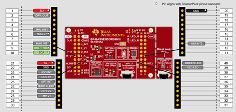
- BASSENSORS BOOSTXL-BASSENSORS
- BASSENSORSMKII BP-BASSENSORSMKII
The table below summarizes the boards (LaunchPads and BoosterPacks) that are supported by this tutorial. Unless otherwise noted, any BoosterPack can be used with any LaunchPad without restrictions.
| Boards | On-board Sensors | Notes |
|---|---|---|
| CC3235SF | TMP116 | the TMP116 alert pin is not connected; the power pin of the HDC sensors on the BoosterPacks is not connected to the MCU - to use these sensors, the HDC's power pin must be driven low |
| CC3220SF | TMP006 | the TMP006 is not supported by ASCStudio |
| CC26X2R1 | (none) | |
| CC1352R1 | (none) | |
| CC1352R (LPSTK) | HDC2080 | requires separate XDC110 emulator available on the LAUNCHXL-CC26X2R1 or similar LaunchPad |
| BASSENSORS | HDC2010, TMP116 | the alert pin for the HDC is not (by default) connected to the MCU on the CC32XX lauchpads |
| BASSENSORSMKII | HDC2080, TMP117 | the alert pin for the HDC is not (by default) connected to the MCU on the CC32XX lauchpads |
Software for desktop development
The only software required for this tutorial is Code Composer Studio and a SimpleLink SDK. Use the links below to access the appropriate products.
Code Composer Studio
- Code Composer Studio 10.2 or compatible
SimpleLink device-family SDKs Select the SDK(s) that support the LaunchPad(s) you plan to use for this tutorial.
- SimpleLink CC32xx SDK 4.40 or compatible
- SimpleLink CC13xx CC26xx SDK 5.30 or compatible
Task 0 – ASCStudio Code Generation
To get a feel for the capabilities of ASCStudio, it's possible to run this tool from the cloud.
- Open the cloud-based ASCStudio
- Select and add a sensor
- Examine the generated files
Task 1 – Install the ASCStudio Product
In order to use ASCStudio within a local CCS desktop environment, you must first download and install ASCStudio to your desktop.
Open the "Package Manager" from "TI Resource Explorer"
- Start CCS and select
View→Resource Explorer - Click the "hamburger" icon (next to the "Keywords filter" text box) and select "Package Manager"
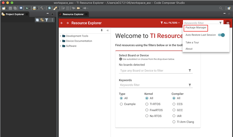
- Start CCS and select
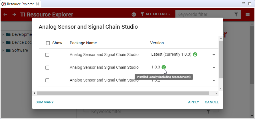
Scroll to the "Analog Signal Chain Studio" package and click on the "More" arrow to view version options
Select and install the latest "Analog Signal Chain Studio"
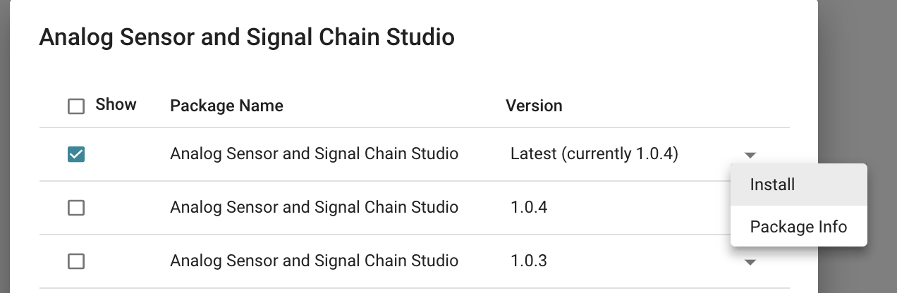
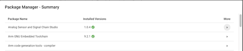
Watch for the small red check mark in the toolbar and the green check next to the version you selected to install.
When installation is complete the dialog will be updated as follows:
Task 2 – Create an "empty" ASCStudio project
In this task, starting from scratch, we create and "empty" project that can combines both a SimpleLink SDK and ASCStudio in a single configuration. By starting from an empty project, the subsequent instructions apply to any starting point project from the SDK: once use can add a sensor to an empty project, you'll be able to add the same sensor to any project.
Import an "empty" SDK project
We start by importing a minimal SDK project that supports the RTOS of your choice: TI-RTOS, FreeRTOS, or NoRTOS.
Project→Import CCS Projects...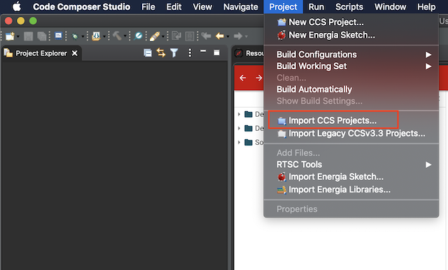
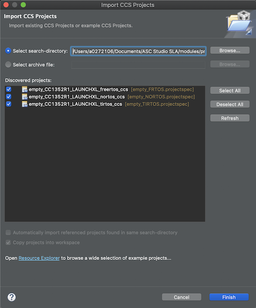
Navigate to an "empty" project for your LaunchPad; "empty" projects are included in each SDK but some examples are also included in here.
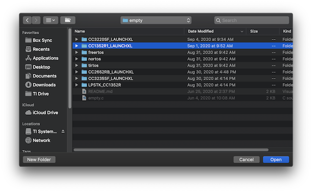
Click "Select Folder", "Select All", and "Finish"
Add BoosterPacks to the project
If your LaunchPad doesn't already have a sensor you want to use, you
must add a BoosterPack to your configuration. To do this, you must
manually edit the project's .syscfg file to include a call to
scripting.addHardware().
For example, to add the BASSENSORS BoosterPack to your configuration,
you must add the following line to the beginning of empty.syscfg:
scripting.addHardware("/ti/boards/boosterpacks/BOOSTXL-BASSENSORS");
To add the BASSENSORSMKII BoosterPack to your configuration,
add the following line to empty.syscfg:
scripting.addHardware("/ti/boards/boosterpacks/BP-BASSENSORSMKII");
Several complete "empty" .syscfg script examples are provided in the "Source
Files" section below.
By default, CCS opens the SysConfig tool to edit .syscfg files.
However, it's also possible to edit these files textually.
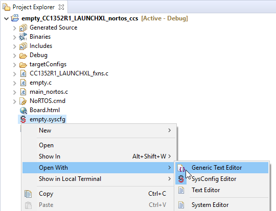
- Right click the
.syscfgfile in the Project Explorer view - Select "Open With..." and select the editor of your choice
Note: The next time you double-click the .syscfg file, CCS
will use the text editor you choose above to open the file. To
restore SysConfig as the default editor, simply repeat the process
above and select "SysConfig Editor".
Add ASCStudio to the project
Once ASCStudio is installed, you can add the ability to configure sensors to any CCS project. In this step, we add ASCStudio to the "empty" SDK project created earlier.
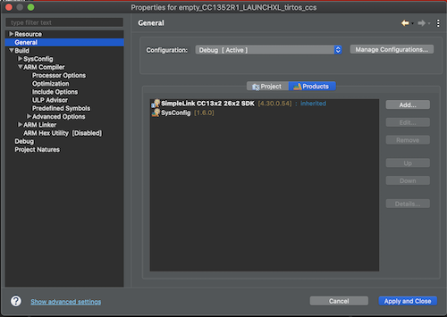
Open the project's "Products" properties settings
- Right-click the project and open "Show Build Settings ..."
- Select "General" in the left pane and the "Products" tab in the right pane
- Click the "Add..." button
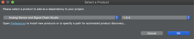
Select the "Analog Signal Chain Studio" product and click "OK"
Click the "Up" button to place this product above the SimpleLink SDK
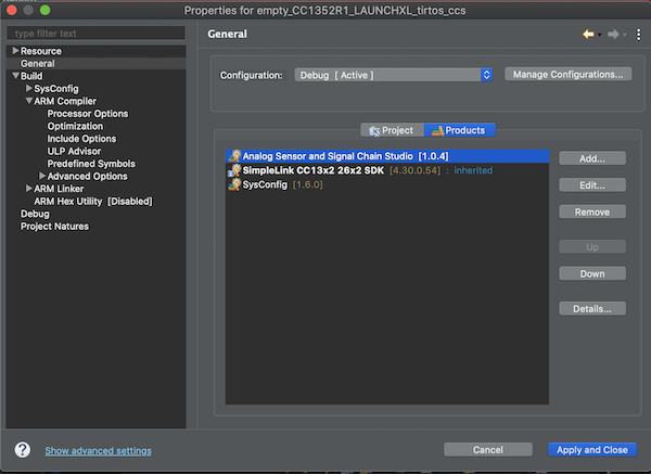
Analog Signal Chain Studio must appear first
The order of products in the Products list makes a difference: a product can implicitly update products that appear after it. In this case, ASCStudio leverages early access capabilities of TI Drivers by overriding some files in TI-DRIVERS; in subsequent releases, these overrides will be unnecessary and the order will no longer be necessary.
Click "Apply and Close"
Task 3 – Add a Sensor to the Project
In Task 2 we created an "empty" project that combines a SimpleLink SDK product with the ASCStudio product. From this point, we can now add one or more sensors, configure them, and build an application that runs on a LaunchPad, reads data from the sensors, and displays the results in the CCS debugger.
Add a sensor and configure it
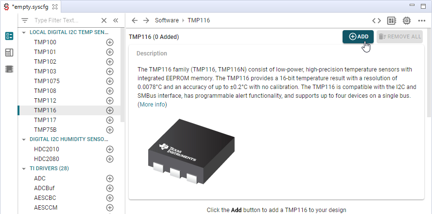
Open
empty.syscfgusing SysConfig and add a sensor- Double-click
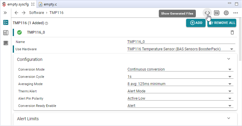
empty.syscfgin the CCS Project Explorer - Click on a sensor supported by your LaunchPad (plus any optionally added BoosterPack)
- Click "Add" to add a sensor and (optionally) give it a name; this name will be used in your application to control the sensor.
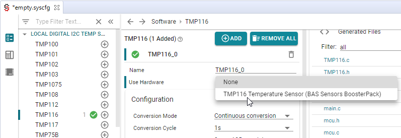
- Double-click
Use the sensor's "Use Hardware" configuration option to connect this sensor to one of the hardware components (i.e. BoosterPack) connected to the LaunchPad
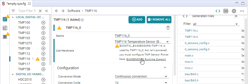
Resolve any warnings or errors
If there are any errors or warnings in the previous steps, the error and/or warning messages should guide you to how to fix the issue.
Some other warnings you're likely to encounter include the following:
- BASSSENSOR BoosterPacks require each sensor to be individually powered via an MCU GPIO output pin
- LaunchPad sensors are often at an I2C address that differs from their default and, as a result, the address may need to be explicitly set
- The BASSENSORS boosterpacks include an I2C optical sensor, OPT3001, which has an I2C address that conflicts with the optical sensor that is present on some launchpads. SysConfig warns about this conflict (which is not a problem as long as these sensors are not used in the application). The TI-DRIVERS I2C SysConfig interface provides a check box, "Ignore Unused Address Conflicts" to disable warnings about conflicts among unused sensors
- The CC3235 LaunchPad does not connect the TMP116's alert pin. to the MCU and, as a result, an attempt to configure an alert pin for this sensor triggers an error
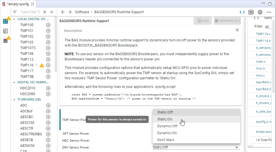
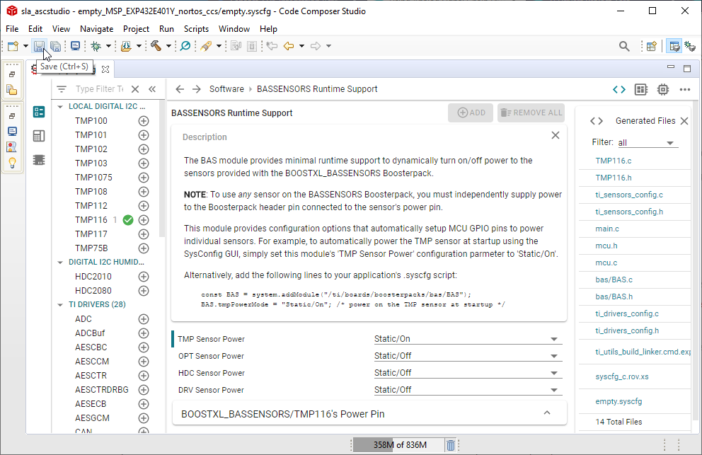
For example, the image below illustrates the first of these warnings: by default, the TMP116 on the BASSENSORS BoosterPack is being used but it's not being powered. Click on the link in the SysConfig warning message to select how you want to handle this issue.
By selecting "Static/On", SysConfig will initialize the appropriate GPIO pin to provide power for the sensor as part of the application's startup initialization.
When you're done configuring the sensor(s), click the save button to
save your changes before proceeding to build the project; you need to
update empty.c to read data from the sensor!
Task 4 – Read Data from the Sensor
In this task, we'll update empty.c to use the sensor APIs generated
by SysConfig, build a minimal application that periodically reads data
from the configured sensors, and visualize the data in real-time.
Each sensor's API header file fully documents the semantics of each sensor method, its parameters, and return value. But SysConfig goes beyond simply generating the APIs, it also generates a basic "main" application that can be used as a whole or part of source code "snippets".
Update empty.c to read sensor data
To simplify the creation of applications that use the sensor API's,
ASCStudio generates a complete (albeit simple) portable main.c application
that reads data from each of the sensors configured via SysConfig.
There are (at least) two ways to use main.c to create a working
application: either
- copy-and-paste contents from
main.cover/intoempty.c, or - simply exclude
empty.cfrom the build
Note that files generated by SysConfig are not written to the
filesystem until you build the project, you must copy lines
of main.c from within SysConfig itself.
Click on the "<>" button at the top of the right-most SysConfig pane
Click on the file you want to view (in this case,
main.c)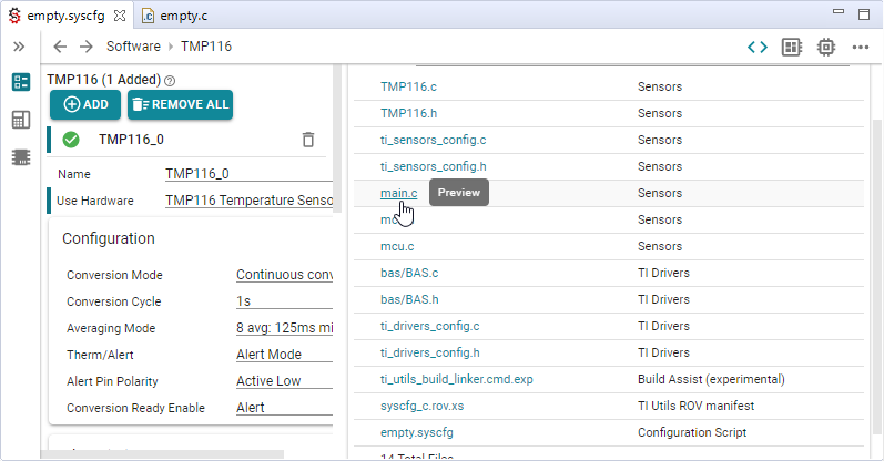
Click anywhere in the preview to select code to copy; for example, to copy the entire file, type
Ctrl-Afollowed byCtrl-Cto copy all lines to the clipboard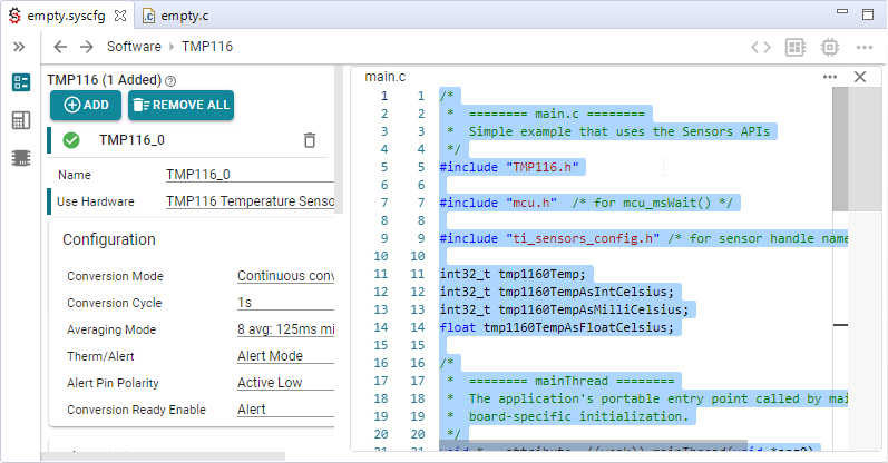
- For this example, the copied code would then be used to replace the entirety of the project's 'empty.c' file
The exclude "trick" has the advantage that it significantly decreases
the configure-build-debug cycle time; the ASCStudio generated main.c
becomes the application, so there's no need to author any code before
using the sensor.
- Right click
empty.c Select "Exclude from Build"
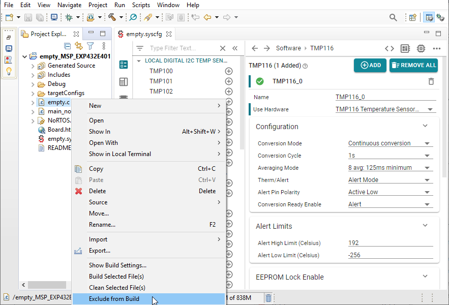
Notice that files excluded from the build are "decorated" by the Project Explorer with a slash through their icon and their names appear in a grey-colored font.
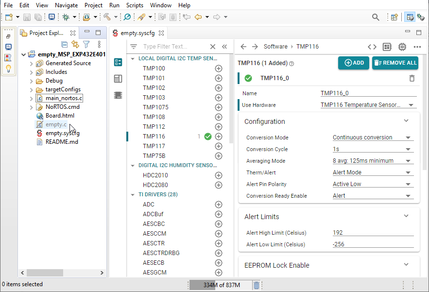
Once excluded, the generated main.c becomes the application, and all
changes made to the sensors are automatically reflected in main.c
without having to write/update any code.
Build and debug
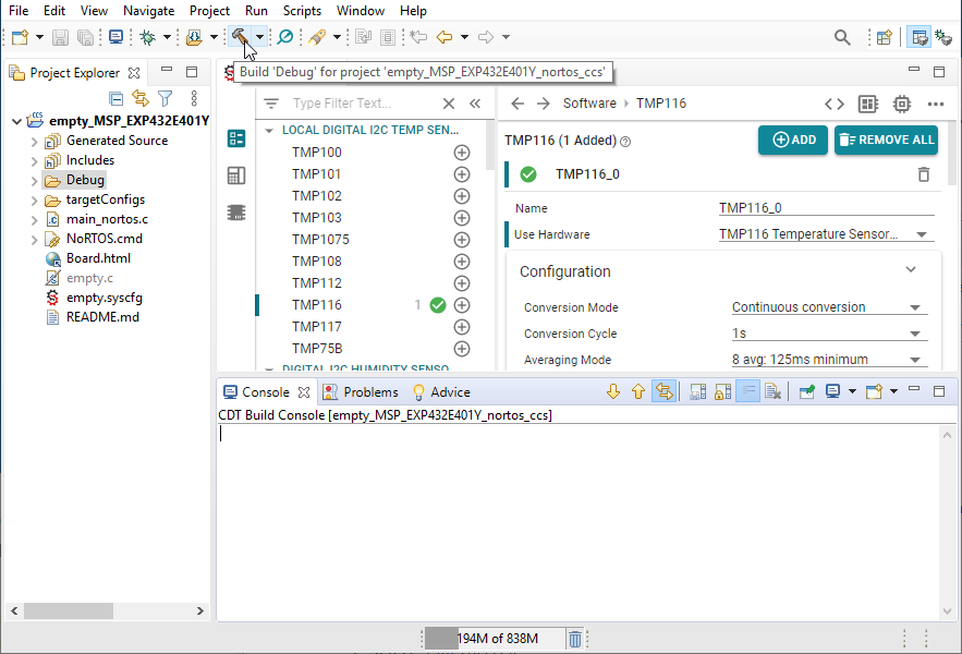
From the main CCS toolbar
Click the main toolbar "Build" button
Click the main toolbar "Debug" button
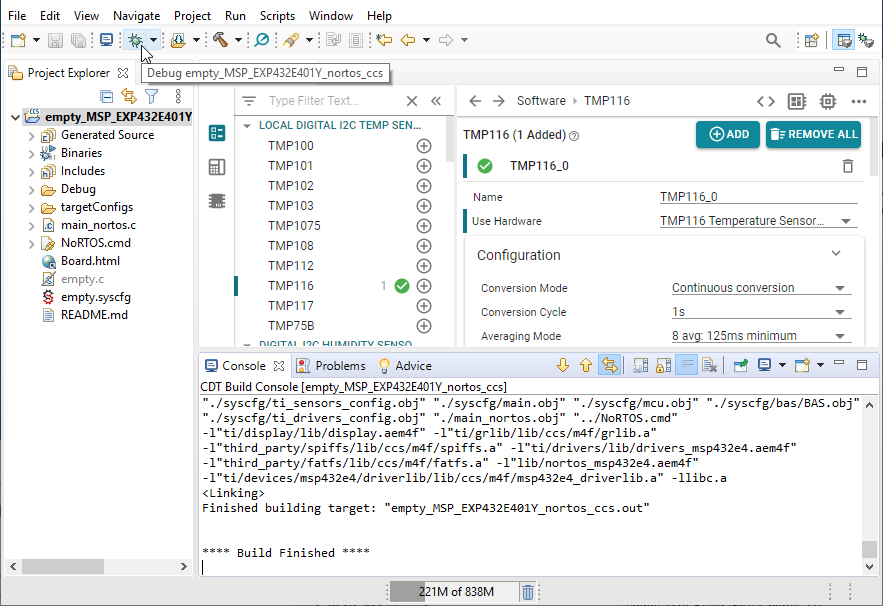
By default, CCS will load, start, and stop the application at
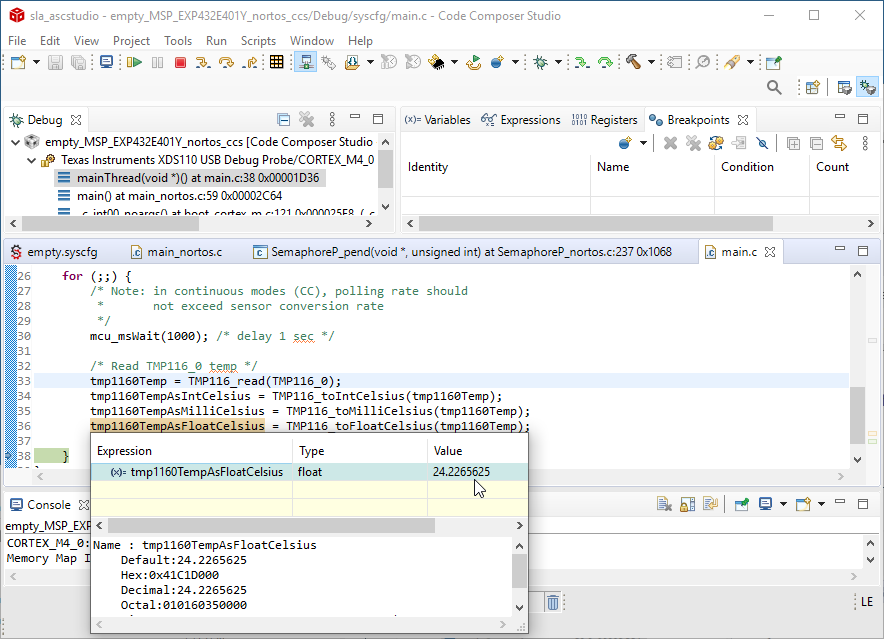
main(). At this point, you should
- Set a breakpoint at
mainThreadand click the run button Single step until the conversion variables are set and examine them by hovering the mouse of the variables you like to inspect
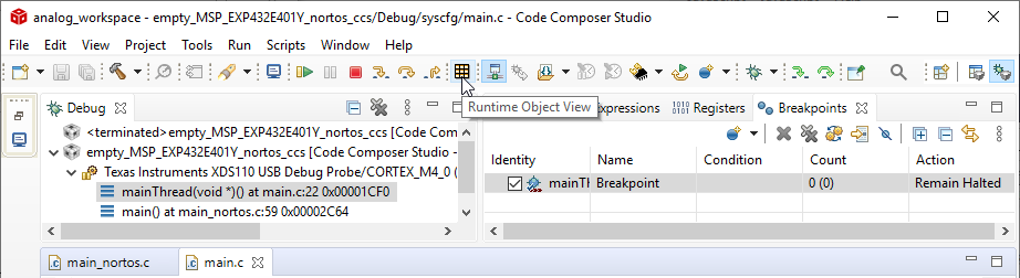
Visualize sensor data
Beyond using debugger breakpoints and raw memory displays to verify proper operation of an application, it is also possible use the Runtime Object View (ROV) tool. The ROV tool provides a variety of ways to non-intrusively read and visualize the state of any running system.
This section illustrates the use of ROV to create a real-time non-intrusive plot of the temperature values acquired from the TMP116 sensor configured in Task 3.1. For more detailed documentation how to use ROV from within CCS, see Connecting to ROV of the ROV User Guide.
Displaying real-time updates from the sensor
ROV opens in a new window and automatically opens a "connect" dialog.
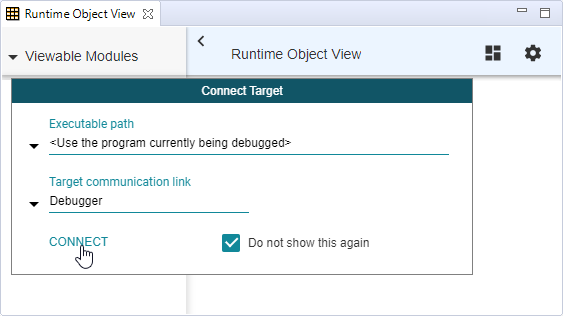
Then click CONNECT. By selecting Do not show this again then the next
time you open ROV it will automatically reconnect, simplifying the
edit-build-debug cycle.
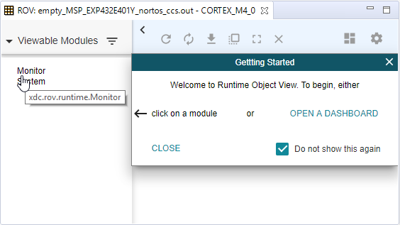
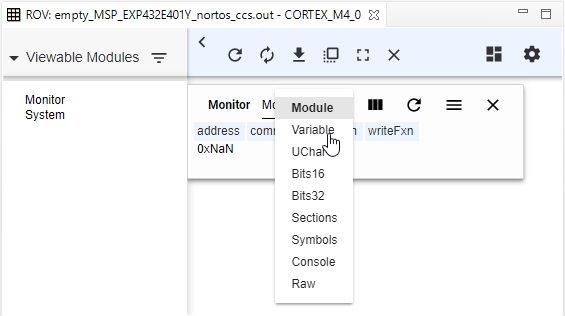
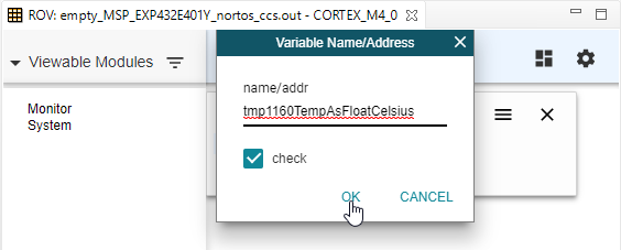
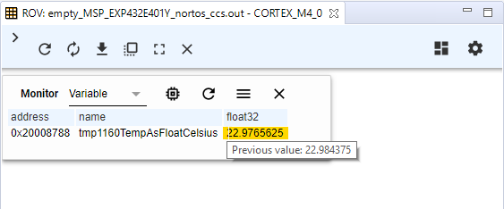
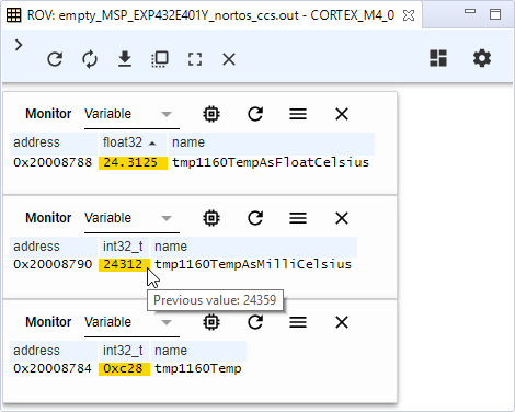
Select the Variable view provided by the Monitor window's menu bar.
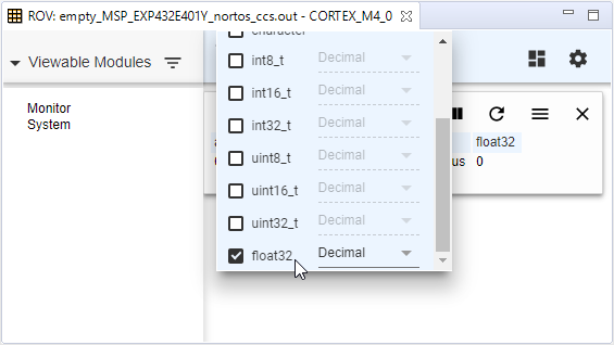
Click the Column settings button to hide unwanted columns and set
the display radix for the value
Click the Refresh all button to read the variable's value
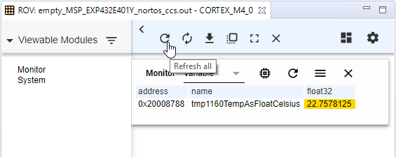
Hover the mouse over the highlighted value to see the previous value
Click the Repeat refresh button to periodically poll the target and
update to displayed value.
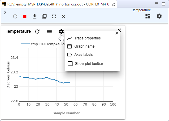
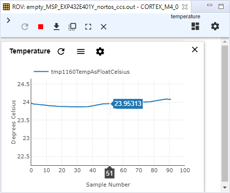
Creating a real-time plot of sensor values
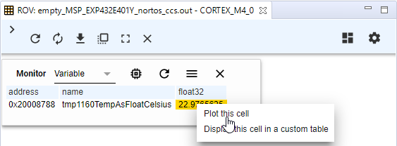
Click the Repeat refresh to see real-time updates
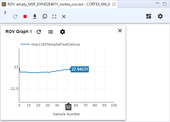
For more information about ROV and how it can be used to monitor a running embedded system see the ROV User Guide.
Source Files
Warning!
The files provided below reference expected outputs using the steps outlined in the tasks of this SimpleLink Academy Lab. They are not intended for direct use and will vary based on product variant and/or SDK version.
Minimal configuration scripts
/* Power is required to ensure Board_init() configures MCU clocks */
const Power = scripting.addModule("/ti/drivers/Power");

/* Specify RTOS to ensure generated files are correct */
const RTOS  = scripting.addModule("/ti/drivers/RTOS");
RTOS.name   = "NoRTOS"; /* alternatives include: "FreeRTOS" or "TI-RTOS" */
Minimum configuration - common to all SDK apps
/* add BOOSTXL-BASSENSORS hardware components to the LaunchPad */
scripting.addHardware("/ti/boards/boosterpacks/BOOSTXL-BASSENSORS");

/* Power is required to ensure Board_init() configures MCU clocks */
const Power = scripting.addModule("/ti/drivers/Power");

/* Specify RTOS to ensure generated files are correct */
const RTOS  = scripting.addModule("/ti/drivers/RTOS");
RTOS.name   = "NoRTOS"; /* alternatives include: "FreeRTOS" or "TI-RTOS" */
Minimum configuration when using the BOOSTXL-BASSENSORS BoosterPack
/* add BP-BASSENSORSMKII hardware components to the LaunchPad */
scripting.addHardware("/ti/boards/boosterpacks/BP-BASSENSORSMKII");

/* Power is required to ensure Board_init() configures MCU clocks */
const Power = scripting.addModule("/ti/drivers/Power");

/* Specify RTOS to ensure generated files are correct */
const RTOS  = scripting.addModule("/ti/drivers/RTOS");
RTOS.name   = "NoRTOS"; /* alternatives include: "FreeRTOS" or "TI-RTOS" */
Minimum configuration when using the BP-BASSENSORSMKII BoosterPack
Minimal sensor "hello world" application
#include "TMP116.h"            /* declares all TMP116 functions and types */
#include "mcu.h"               /* declares mcu_msWait() */

#include "ti_sensors_config.h" /* declares config-specific names: INDOOR */

int32_t temp;                  /* raw sensor conversion value */
int32_t tempAsMilliCelsius;    /* raw value converted to degrees milli-C */

/*
 *  ======== mainThread ========
 *  Portable application entry point called by main()
 */
void *mainThread(void *arg0)
{
    /* init sensor with values specified in ti_sensors_config.c */
    TMP116_config(INDOOR);

    for (;;) {
        mcu_msWait(1000);  /* delay 1 sec */

        /* Read INDOOR temp and convert to milli-Celsius */
        temp = TMP116_read(INDOOR);
        tempAsMilliCelsius = TMP116_toMilliCelsius(temp);
     }
}
Portable TMP116 sensor read application
/* Add BoosterPack hardware data to SysConfig's hardware model */
const BOOSTXL_BASSENSORS = scripting.addHardware("/ti/boards/boosterpacks/BOOSTXL-BASSENSORS");

/* Specify RTOS to ensure generated files are correct */
const RTOS  = scripting.addModule("/ti/drivers/RTOS");
RTOS.name   = "NoRTOS"; /* alternatives include: "FreeRTOS" or "TI-RTOS" */

/**
 * Import the modules used in this configuration.
 */
const BAS    = scripting.addModule("/ti/boards/boosterpacks/bas/BAS");
const Power  = scripting.addModule("/ti/drivers/Power");
const TMP116 = scripting.addModule("/ti/sensors/tempsensor/TMP116");
const INDOOR = TMP116.addInstance();

/**
 * Write custom configuration values to the imported modules.
 */
BAS.tmpPowerMode = "Static/On";

INDOOR.$name     = "INDOOR";
INDOOR.$hardware = BOOSTXL_BASSENSORS.components.TMP116;
Device-independent TMP116 configuration script
#include <stddef.h>

#include <ti/drivers/Board.h>

extern void *mainThread(void *arg0); /* portable application entry point */

int main(void)
{
    /* run board-specific initialization with interrupts disabled */
    Board_init(); /* generated by SysConfig; see ti_drivers_config.c */

    /* initialize RTOS (TI-RTOS, FreeRTOS, ... */
        :

    /* use RTOS to create a thread with mainThread as its entry point  */
    mainThread(NULL); /* should never return */

    while (1) {}      /* just in case */
}
OS-specific pseudo-code startup of an OS-independent application
This work is licensed under a Creative Commons Attribution-NonCommercial-NoDerivatives 4.0 International License.