Introduction
SysConfig is a tool that helps simplify the configuration of your application on a SimpleLink device.
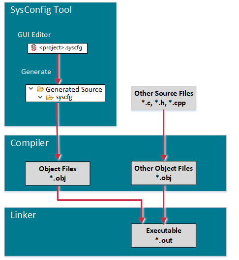
The basic idea of SysConfig is to allow intuitive and natural configuration of key components in an application. The SysConfig tool will generate source code to configure these components (e.g. TI Drivers, stacks, etc.) based on the settings in the SysConfig configuration file (i.e. .syscfg). This generated code is then included in the application.
For example, SysConfig will create and fill in all the 'C' structures needed by the TI Driver modules.
This lab is an introduction to SysConfig and will focus on its integration with TI Drivers modules (e.g. UART, I2C, etc.). Additional labs will be available for other key components (e.g. Networking stacks, BLE stack, etc.) but this lab is considered the starting point to understand and learn the power of SysConfig.
SysConfig is not dependent on an RTOS, compiler toolchain, or IDE. Additionally SysConfig is available
- with CCS Desktop (which this lab will focus on).
- with CCS Cloud
- as a stand-alone desktop tool
- as a cmdline tool
The tasks in this lab session are targeted to be completed within an hour time frame.
What SysConfig is not
Currently SysConfig is generally focused on generating configuration code. For example, the tool generates the configuration code for TI Drivers, but it does not generate code for the Driver init or open calls. For example, the application writer can use SysConfig to configure an I2C peripheral, but the writer must supply the calls to I2C_init, I2C_open, and I2C_transfer. Please refer to the documentation for each component in SysConfig for more information.
Here's what we'll learn
- Introduction to SysConfig
- Learn how to use SysConfig to configure TI Drivers in your application
More specific guidance for certain device families
This SimpleLink Academy lab supports various families of devices. Please note instructions are sometimes divided in the following way.
Prerequisites
Recommended background reading
- SimpleLink SDK User Guide's SysConfig section
- SysConfig Product Page
Software for development
- Any SimpleLink SDK installed on your computer:
- Desktop Code Composer Studio as specified in the SimpleLink SDK Release Notes
Hardware requirements
You can use this workshop with any cc13xx, CC26xx, CC32xx, MSP432E4, or MSP432P4 LaunchPad Development Kit.
TI Driver Configuration
TI Drivers rely on the application to supply the driver configuration. The majority of this configuration is supplied in 'C' structures and arrays. For example, the below code (generated by SysConfig) sets up a I2C peripheral to be used in a TI Drivers example for the CC3235S_LAUNCHXL board.
/*
 *  =============================== I2C ===============================
 */

#include <ti/drivers/I2C.h>
#include <ti/drivers/i2c/I2CCC32XX.h>
#include <ti/devices/cc32xx/inc/hw_ints.h>
#include <ti/devices/cc32xx/inc/hw_memmap.h>

#define CONFIG_I2C_COUNT 1

I2CCC32XX_Object i2cCC32XXObjects[CONFIG_I2C_COUNT];

const I2CCC32XX_HWAttrsV1 i2cCC32XXHWAttrs[CONFIG_I2C_COUNT] = {
    /* CONFIG_I2C_TMP */
    /* LaunchPad I2C */
    {
        .baseAddr = I2CA0_BASE,
        .intNum = INT_I2CA0,
        .intPriority = (~0),
        .sclTimeout = 0x0,
        .clkPin  = I2CCC32XX_PIN_01_I2C_SCL,
        .dataPin = I2CCC32XX_PIN_02_I2C_SDA
    },
};

const I2C_Config I2C_config[CONFIG_I2C_COUNT] = {
    /* CONFIG_I2C_TMP */
    /* LaunchPad I2C */
    {
        .object = &i2cCC32XXObjects[CONFIG_I2C_TMP],
        .hwAttrs = &i2cCC32XXHWAttrs[CONFIG_I2C_TMP]
    },
};

const uint_least8_t CONFIG_I2C_TMP_CONST = CONFIG_I2C_TMP;
const uint_least8_t I2C_count = CONFIG_I2C_COUNT;
Generated code by SysConfig
/*
 *  =============================== I2C ===============================
 */

#include <ti/drivers/I2C.h>
#include <ti/drivers/i2c/I2CCC26XX.h>
#include <ti/drivers/power/PowerCC26XX.h>

#include <ti/devices/DeviceFamily.h>
#include DeviceFamily_constructPath(inc/hw_ints.h)
#include DeviceFamily_constructPath(inc/hw_memmap.h)
#include DeviceFamily_constructPath(driverlib/ioc.h)

#define CONFIG_I2C_COUNT 1

/*
 *  ======== i2cCC26xxObjects ========
 */
I2CCC26XX_Object i2cCC26xxObjects[CONFIG_I2C_COUNT];

/*
 *  ======== i2cCC26xxHWAttrs ========
 */
const I2CCC26XX_HWAttrsV1 i2cCC26xxHWAttrs[CONFIG_I2C_COUNT] = {
    /* CONFIG_I2C_0 */
    {
        .baseAddr    = I2C0_BASE,
        .powerMngrId = PowerCC26XX_PERIPH_I2C0,
        .intNum      = INT_I2C_IRQ,
        .intPriority = (~0),
        .swiPriority = 0,
        .sclPin      = CONFIG_GPIO_I2C_0_SCL,
        .sclPinMux   = IOC_PORT_MCU_I2C_MSSCL,
        .sdaPin      = CONFIG_GPIO_I2C_0_SDA,
        .sdaPinMux   = IOC_PORT_MCU_I2C_MSSDA
    },
};

/*
 *  ======== I2C_config ========
 */
const I2C_Config I2C_config[CONFIG_I2C_COUNT] = {
    /* CONFIG_I2C_0 */
    {
        .object      = &i2cCC26xxObjects[CONFIG_I2C_0],
        .hwAttrs     = &i2cCC26xxHWAttrs[CONFIG_I2C_0]
    },
};

const uint_least8_t CONFIG_I2C_0_CONST = CONFIG_I2C_0;
const uint_least8_t I2C_count = CONFIG_I2C_COUNT;
Generated code by SysConfig
This approach minimizes runtime allocation and overall footprint of the application.
Runtime usage of the TI Drivers
To use a TI Driver instance, you still must open it (e.g. UART_open must be called by the application) regardless of the method used to supply the TI Driver configuration.
The following two sections show the two ways this configuration is supplied
- SysConfig: source code is generated based on configuration in SysConfig
- Legacy: application supplies the source code
SysConfig Approach
With SysConfig, the configuration of the TI Drivers is the same, but instead
of having the application writer supply the 'C' structures/arrays (Legacy
Approach below), the SysConfig tool generates the 'C' code for you instead. Let's
take a look at how this is reflected in the empty drivers projects.
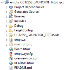
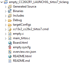
The .syscfg file in a project holds all the configuration for the TI Drivers that will be used by the application. As part of the build, SysConfig will parse the .syscfg file and generate the needed 'C' structures/arrays for the TI Drivers.
The Generated Source folder also contains the generated source files. It was
provided to allow a user to quickly see the generated files instead of going into
the Debug directory.
Note
This example's default CCS Build Configuration is
Debug. There are some examples in the SDK that have Release as the default
CCS Build Configuration (so the directory's name would be Release instead
in those examples accordingly).
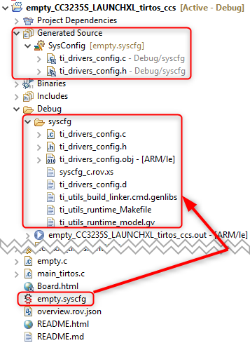
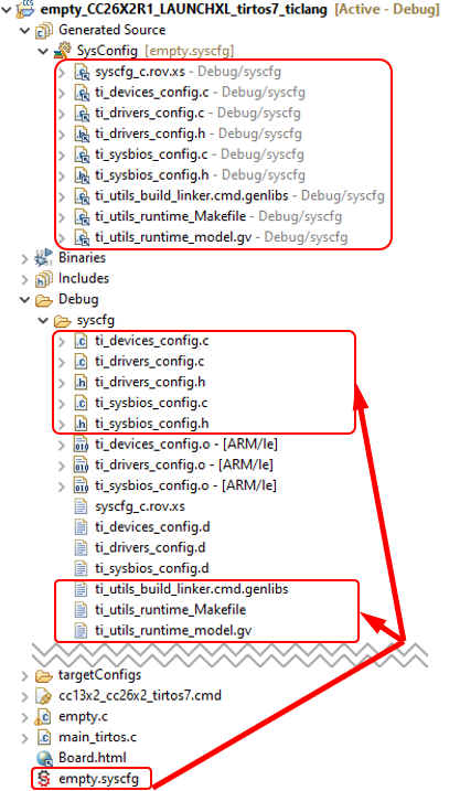
Let's look a bit closer at some of the files in the Debug\syscfg directory:
- ti_drivers_config.c/.h: Driver configuration source files that will be compiled and linked into the application.
- ti_sysbios_config.c/.h: TI-RTOS7 (SysBios) configuration source files that will be compiled and linked into the application (if present).
- ti_devices_config.c: Device configuration file (CCFG) that will be compiled and linked into the application (if present).
- ti_utils_build_linker.cmd.genlibs: Additional linker file for the project. More details on this later.
- syscfg_c.rov.xs: Brings in additional Runtime Object Views (if present). More details on this later.
Editing the .syscfg file
TI recommends that the .syscfg file only be modified via the SysConfig tool.
Then if you peek into ti_drivers_config.c for this example, we only see the configuration that is needed for the application (e.g. no I2C configuration since the empty example does not use I2C).
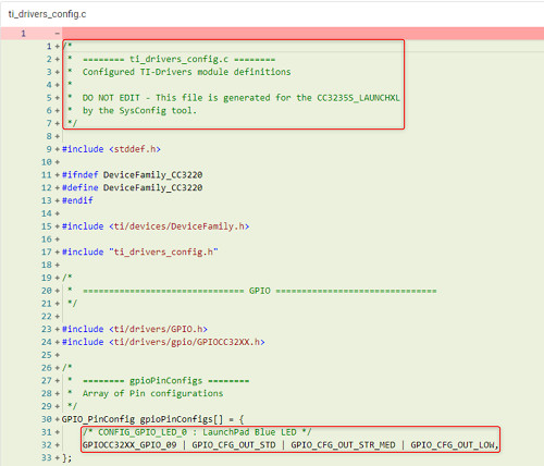
This the ti_drivers_config.c source code obtained for the CC3235S_LAUNCHXL board
   /*
    *  ======== ti_drivers_config.c ========
    *  Configured TI-Drivers module definitions
    *
    *  DO NOT EDIT - This file is generated for the CC3235S_LAUNCHXL
    *  by the SysConfig tool.
    */

   #include <stddef.h>

   #ifndef DeviceFamily_CC3220
   #define DeviceFamily_CC3220
   #endif

   #include <ti/devices/DeviceFamily.h>

   #include "ti_drivers_config.h"

   /*
    *  =============================== GPIO ===============================
    */

   #include <ti/drivers/GPIO.h>
   #include <ti/drivers/gpio/GPIOCC32XX.h>

   /*
    *  ======== gpioPinConfigs ========
    *  Array of Pin configurations
    */
   GPIO_PinConfig gpioPinConfigs[] = {
       /* CONFIG_GPIO_LED_0 : LaunchPad Blue LED */
       GPIOCC32XX_GPIO_09 | GPIO_CFG_OUT_STD | GPIO_CFG_OUT_STR_MED | GPIO_CFG_OUT_LOW,
   };

   /*
    *  ======== gpioCallbackFunctions ========
    *  Array of callback function pointers
    *
    *  NOTE: Unused callback entries can be omitted from the callbacks array to
    *  reduce memory usage by enabling callback table optimization
    *  (GPIO.optimizeCallbackTableSize = true)
    */
   GPIO_CallbackFxn gpioCallbackFunctions[] = {
       /* CONFIG_GPIO_LED_0 : LaunchPad Blue LED */
       NULL,
   };

   /*
    *  ======== GPIOCC32XX_config ========
    */
   const GPIOCC32XX_Config GPIOCC32XX_config = {
       .pinConfigs = (GPIO_PinConfig *)gpioPinConfigs,
       .callbacks = (GPIO_CallbackFxn *)gpioCallbackFunctions,
       .numberOfPinConfigs = 1,
       .numberOfCallbacks = 1,
       .intPriority = (~0)
   };


   /*
    *  =============================== Power ===============================
    */
   #include <ti/drivers/Power.h>
   #include <ti/drivers/power/PowerCC32XX.h>
   #include <ti/devices/cc32xx/driverlib/prcm.h>
   #include "ti_drivers_config.h"

   extern void PowerCC32XX_initPolicy(void);
   extern void PowerCC32XX_sleepPolicy(void);
   PowerCC32XX_ParkInfo parkInfo[];
   /*
    *  This structure defines the configuration for the Power Manager.
    */
   const PowerCC32XX_ConfigV1 PowerCC32XX_config = {
       .policyInitFxn             = PowerCC32XX_initPolicy,
       .policyFxn                 = PowerCC32XX_sleepPolicy,
       .enterLPDSHookFxn          = NULL,
       .resumeLPDSHookFxn         = NULL,
       .enablePolicy              = false,
       .enableGPIOWakeupLPDS      = true,
       .enableGPIOWakeupShutdown  = true,
       .enableNetworkWakeupLPDS   = true,
       .wakeupGPIOSourceLPDS      = PRCM_LPDS_GPIO13,
       .wakeupGPIOTypeLPDS        = PRCM_LPDS_FALL_EDGE,
       .wakeupGPIOFxnLPDS         = NULL,
       .wakeupGPIOFxnLPDSArg      = 0,
       .wakeupGPIOSourceShutdown  = PRCM_HIB_GPIO13,
       .wakeupGPIOTypeShutdown    = PRCM_HIB_RISE_EDGE,
       .ramRetentionMaskLPDS      = PRCM_SRAM_COL_1|PRCM_SRAM_COL_2|PRCM_SRAM_COL_3|PRCM_SRAM_COL_4,
       .keepDebugActiveDuringLPDS = false,
       .ioRetentionShutdown       = PRCM_IO_RET_GRP_0|PRCM_IO_RET_GRP_1|PRCM_IO_RET_GRP_2|PRCM_IO_RET_GRP_3,
       .pinParkDefs               = parkInfo,
       .numPins                   = 31
   };


   #include <ti/drivers/power/PowerCC32XX.h>

   /*
    * This table defines the parking state to be set for each parkable pin
    * during LPDS. (Device resources must be parked during LPDS to achieve maximum
    * power savings.)  If the pin should be left unparked, specify the state
    * PowerCC32XX_DONT_PARK.  For example, for a UART TX pin, the device
    * will automatically park the pin in a high state during transition to LPDS,
    * so the Power Manager does not need to explictly park the pin.  So the
    * corresponding entries in this table should indicate PowerCC32XX_DONT_PARK.
    */
   PowerCC32XX_ParkInfo parkInfo[] = {
   /*        PIN                    PARK STATE              Pin Alias
      -----------------  ------------------------------     ---------------*/

     {PowerCC32XX_PIN01, PowerCC32XX_WEAK_PULL_DOWN_STD},   /* GP10 */
     {PowerCC32XX_PIN02, PowerCC32XX_WEAK_PULL_DOWN_STD},   /* GP11 */
     {PowerCC32XX_PIN03, PowerCC32XX_WEAK_PULL_DOWN_STD},   /* GP12 */
     {PowerCC32XX_PIN04, PowerCC32XX_WEAK_PULL_DOWN_STD},   /* GP13 */
     {PowerCC32XX_PIN05, PowerCC32XX_WEAK_PULL_DOWN_STD},   /* GP14 */
     {PowerCC32XX_PIN06, PowerCC32XX_WEAK_PULL_DOWN_STD},   /* GP15 */
     {PowerCC32XX_PIN07, PowerCC32XX_WEAK_PULL_DOWN_STD},   /* GP16 */
     {PowerCC32XX_PIN08, PowerCC32XX_WEAK_PULL_DOWN_STD},   /* GP17 */
     {PowerCC32XX_PIN13, PowerCC32XX_WEAK_PULL_DOWN_STD},
     {PowerCC32XX_PIN15, PowerCC32XX_WEAK_PULL_DOWN_STD},   /* GP22 */
     {PowerCC32XX_PIN16, PowerCC32XX_WEAK_PULL_DOWN_STD},   /* TDI */
     {PowerCC32XX_PIN17, PowerCC32XX_WEAK_PULL_DOWN_STD},   /* TDO */
     {PowerCC32XX_PIN18, PowerCC32XX_WEAK_PULL_DOWN_STD},   /* GP28 */
     {PowerCC32XX_PIN19, PowerCC32XX_WEAK_PULL_DOWN_STD},   /* TCK */
     {PowerCC32XX_PIN20, PowerCC32XX_WEAK_PULL_DOWN_STD},   /* TMS */
     {PowerCC32XX_PIN21, PowerCC32XX_WEAK_PULL_DOWN_STD},   /* SOP2 */
     {PowerCC32XX_PIN29, PowerCC32XX_WEAK_PULL_DOWN_STD},
     {PowerCC32XX_PIN30, PowerCC32XX_WEAK_PULL_DOWN_STD},
     {PowerCC32XX_PIN45, PowerCC32XX_WEAK_PULL_DOWN_STD},   /* GP31 */
     {PowerCC32XX_PIN50, PowerCC32XX_WEAK_PULL_DOWN_STD},   /* GP00 */
     {PowerCC32XX_PIN52, PowerCC32XX_WEAK_PULL_DOWN_STD},   /* GP32 */
     {PowerCC32XX_PIN53, PowerCC32XX_WEAK_PULL_DOWN_STD},   /* GP30 */
     {PowerCC32XX_PIN55, PowerCC32XX_WEAK_PULL_UP_STD},   /* GP01 */
     {PowerCC32XX_PIN57, PowerCC32XX_WEAK_PULL_UP_STD},   /* GP02 */
     {PowerCC32XX_PIN58, PowerCC32XX_WEAK_PULL_DOWN_STD},   /* GP03 */
     {PowerCC32XX_PIN59, PowerCC32XX_WEAK_PULL_DOWN_STD},   /* GP04 */
     {PowerCC32XX_PIN60, PowerCC32XX_WEAK_PULL_DOWN_STD},   /* GP05 */
     {PowerCC32XX_PIN61, PowerCC32XX_WEAK_PULL_DOWN_STD},   /* GP06 */
     {PowerCC32XX_PIN62, PowerCC32XX_WEAK_PULL_DOWN_STD},   /* GP07 */
     {PowerCC32XX_PIN63, PowerCC32XX_WEAK_PULL_DOWN_STD},   /* GP08 */
     {PowerCC32XX_PIN64, PowerCC32XX_WEAK_PULL_DOWN_STD},   /* GP09 */
   };


   #include <ti/drivers/Board.h>

   /*
    *  ======== Board_initHook ========
    *  Perform any board-specific initialization needed at startup.  This
    *  function is declared weak to allow applications to override it if needed.
    */
   void __attribute__((weak)) Board_initHook(void)
   {
   }

   /*
    *  ======== Board_init ========
    *  Perform any initialization needed before using any board APIs
    */
   void Board_init(void)
   {
       /* ==== /ti/drivers/Power initialization ==== */
       PRCMCC3200MCUInit();
       Power_init();

       Board_initHook();
   }
ti_drivers_config.c
This the ti_drivers_config.c source code obtained for the LAUNCHXL-CC26X2R1 board
    /*
     *  ======== ti_drivers_config.c ========
     *  Configured TI-Drivers module definitions
     *
     *  DO NOT EDIT - This file is generated for the CC26X2R1_LAUNCHXL
     *  by the SysConfig tool.
     */

    #include <stddef.h>
    #include <stdint.h>

    #ifndef DeviceFamily_CC26X2
    #define DeviceFamily_CC26X2
    #endif

    #include <ti/devices/DeviceFamily.h>

    #include "ti_drivers_config.h"

    /*
     *  =============================== GPIO ===============================
     */

    #include <ti/drivers/GPIO.h>
    #include <ti/drivers/gpio/GPIOCC26XX.h>

    /* The range of pins available on this device */
    const uint_least8_t GPIO_pinLowerBound = 0;
    const uint_least8_t GPIO_pinUpperBound = 30;

    /*
     *  ======== gpioPinConfigs ========
     *  Array of Pin configurations
     */
    GPIO_PinConfig gpioPinConfigs[31] = {
        GPIO_CFG_NO_DIR, /* DIO_0 */
        GPIO_CFG_NO_DIR, /* DIO_1 */
        GPIO_CFG_NO_DIR, /* DIO_2 */
        GPIO_CFG_NO_DIR, /* DIO_3 */
        GPIO_CFG_NO_DIR, /* DIO_4 */
        GPIO_CFG_NO_DIR, /* DIO_5 */
        GPIO_CFG_OUTPUT_INTERNAL | GPIO_CFG_OUT_STR_MED | GPIO_CFG_OUT_LOW, /* CONFIG_GPIO_LED_0 */
        GPIO_CFG_NO_DIR, /* DIO_7 */
        GPIO_CFG_NO_DIR, /* DIO_8 */
        GPIO_CFG_NO_DIR, /* DIO_9 */
        GPIO_CFG_NO_DIR, /* DIO_10 */
        GPIO_CFG_NO_DIR, /* DIO_11 */
        GPIO_CFG_NO_DIR, /* DIO_12 */
        GPIO_CFG_NO_DIR, /* DIO_13 */
        GPIO_CFG_NO_DIR, /* DIO_14 */
        GPIO_CFG_NO_DIR, /* DIO_15 */
        GPIO_CFG_NO_DIR, /* DIO_16 */
        GPIO_CFG_NO_DIR, /* DIO_17 */
        GPIO_CFG_NO_DIR, /* DIO_18 */
        GPIO_CFG_NO_DIR, /* DIO_19 */
        GPIO_CFG_NO_DIR, /* DIO_20 */
        GPIO_CFG_NO_DIR, /* DIO_21 */
        GPIO_CFG_NO_DIR, /* DIO_22 */
        GPIO_CFG_NO_DIR, /* DIO_23 */
        GPIO_CFG_NO_DIR, /* DIO_24 */
        GPIO_CFG_NO_DIR, /* DIO_25 */
        GPIO_CFG_NO_DIR, /* DIO_26 */
        GPIO_CFG_NO_DIR, /* DIO_27 */
        GPIO_CFG_NO_DIR, /* DIO_28 */
        GPIO_CFG_NO_DIR, /* DIO_29 */
        GPIO_CFG_NO_DIR, /* DIO_30 */
    };

    /*
     *  ======== gpioCallbackFunctions ========
     *  Array of callback function pointers
     *  Change at runtime with GPIO_setCallback()
     */
    GPIO_CallbackFxn gpioCallbackFunctions[31];

    /*
     *  ======== gpioUserArgs ========
     *  Array of user argument pointers
     *  Change at runtime with GPIO_setUserArg()
     *  Get values with GPIO_getUserArg()
     */
    void* gpioUserArgs[31];

    const uint_least8_t CONFIG_GPIO_LED_0_CONST = CONFIG_GPIO_LED_0;

    /*
     *  ======== GPIO_config ========
     */
    const GPIO_Config GPIO_config = {
        .configs = (GPIO_PinConfig *)gpioPinConfigs,
        .callbacks = (GPIO_CallbackFxn *)gpioCallbackFunctions,
        .userArgs = gpioUserArgs,
        .intPriority = (~0)
    };

    /*
     *  =============================== Power ===============================
     */
    #include <ti/drivers/Power.h>
    #include <ti/drivers/power/PowerCC26X2.h>
    #include "ti_drivers_config.h"

    extern void PowerCC26XX_standbyPolicy(void);
    extern bool PowerCC26XX_calibrate(unsigned int);

    const PowerCC26X2_Config PowerCC26X2_config = {
        .enablePolicy             = true,
        .policyInitFxn            = NULL,
        .policyFxn                = PowerCC26XX_standbyPolicy,
        .calibrateFxn             = PowerCC26XX_calibrate,
        .calibrateRCOSC_LF        = true,
        .calibrateRCOSC_HF        = true,
        .enableTCXOFxn            = NULL
    };

    #include <stdbool.h>

    #include <ti/devices/cc13x2_cc26x2/driverlib/ioc.h>
    #include <ti/devices/cc13x2_cc26x2/driverlib/cpu.h>

    #include <ti/drivers/GPIO.h>

    /* Board GPIO defines */
    #define BOARD_EXT_FLASH_SPI_CS      20
    #define BOARD_EXT_FLASH_SPI_CLK     10
    #define BOARD_EXT_FLASH_SPI_MOSI    9
    #define BOARD_EXT_FLASH_SPI_MISO    8


    /*
     *  ======== Board_sendExtFlashByte ========
     */
    void Board_sendExtFlashByte(uint8_t byte)
    {
        uint8_t i;

        /* SPI Flash CS */
        GPIO_write(BOARD_EXT_FLASH_SPI_CS, 0);

        for (i = 0; i < 8; i++) {
            GPIO_write(BOARD_EXT_FLASH_SPI_CLK, 0); /* SPI Flash CLK */

            /* SPI Flash MOSI */
            GPIO_write(BOARD_EXT_FLASH_SPI_MOSI, (byte >> (7 - i)) & 0x01);
            GPIO_write(BOARD_EXT_FLASH_SPI_CLK, 1);  /* SPI Flash CLK */

            /*
             * Waste a few cycles to keep the CLK high for at
             * least 45% of the period.
             * 3 cycles per loop: 8 loops @ 48 Mhz = 0.5 us.
             */
            CPUdelay(8);
        }

        GPIO_write(BOARD_EXT_FLASH_SPI_CLK, 0);  /* CLK */
        GPIO_write(BOARD_EXT_FLASH_SPI_CS, 1);  /* CS */

        /*
         * Keep CS high at least 40 us
         * 3 cycles per loop: 700 loops @ 48 Mhz ~= 44 us
         */
        CPUdelay(700);
    }

    /*
     *  ======== Board_wakeUpExtFlash ========
     */
    void Board_wakeUpExtFlash(void)
    {
        /* SPI Flash CS*/
        GPIO_setConfig(BOARD_EXT_FLASH_SPI_CS, GPIO_CFG_OUTPUT | GPIO_CFG_OUT_HIGH | GPIO_CFG_OUT_STR_MED);

        /*
         *  To wake up we need to toggle the chip select at
         *  least 20 ns and ten wait at least 35 us.
         */

        /* Toggle chip select for ~20ns to wake ext. flash */
        GPIO_write(BOARD_EXT_FLASH_SPI_CS, 0);
        /* 3 cycles per loop: 1 loop @ 48 Mhz ~= 62 ns */
        CPUdelay(1);
        GPIO_write(BOARD_EXT_FLASH_SPI_CS, 1);
        /* 3 cycles per loop: 560 loops @ 48 Mhz ~= 35 us */
        CPUdelay(560);
    }

    /*
     *  ======== Board_shutDownExtFlash ========
     */
    void Board_shutDownExtFlash(void)
    {
        /*
         *  To be sure we are putting the flash into sleep and not waking it,
         *  we first have to make a wake up call
         */
        Board_wakeUpExtFlash();

        /* SPI Flash CS*/
        GPIO_setConfig(BOARD_EXT_FLASH_SPI_CS, GPIO_CFG_OUTPUT | GPIO_CFG_OUT_HIGH | GPIO_CFG_OUT_STR_MED);
        /* SPI Flash CLK */
        GPIO_setConfig(BOARD_EXT_FLASH_SPI_CLK, GPIO_CFG_OUTPUT | GPIO_CFG_OUT_LOW | GPIO_CFG_OUT_STR_MED);
        /* SPI Flash MOSI */
        GPIO_setConfig(BOARD_EXT_FLASH_SPI_MOSI, GPIO_CFG_OUTPUT | GPIO_CFG_OUT_LOW | GPIO_CFG_OUT_STR_MED);
        /* SPI Flash MISO */
        GPIO_setConfig(BOARD_EXT_FLASH_SPI_MISO, GPIO_CFG_IN_PD);

        uint8_t extFlashShutdown = 0xB9;

        Board_sendExtFlashByte(extFlashShutdown);

        GPIO_resetConfig(BOARD_EXT_FLASH_SPI_CS);
        GPIO_resetConfig(BOARD_EXT_FLASH_SPI_CLK);
        GPIO_resetConfig(BOARD_EXT_FLASH_SPI_MOSI);
        GPIO_resetConfig(BOARD_EXT_FLASH_SPI_MISO);
    }


    #include <ti/drivers/Board.h>

    /*
     *  ======== Board_initHook ========
     *  Perform any board-specific initialization needed at startup.  This
     *  function is declared weak to allow applications to override it if needed.
     */
    void __attribute__((weak)) Board_initHook(void)
    {
    }

    /*
     *  ======== Board_init ========
     *  Perform any initialization needed before using any board APIs
     */
    void Board_init(void)
    {
        /* ==== /ti/drivers/Power initialization ==== */
        Power_init();

        /* ==== /ti/devices/CCFG initialization ==== */

        /* ==== /ti/drivers/GPIO initialization ==== */
        /* Setup GPIO module and default-initialise pins */
        GPIO_init();

        Board_shutDownExtFlash();

        Board_initHook();
    }
ti_drivers_config.c
Name changes on Driver Macros
The SimpleLink SDK 3.30 release standardized SysConfig as the default approach
for example applications. This release also standardized the legacy driver macros
to avoid name-space collisions. The names like Board_GPIO_LED_ON are now
CONFIG_GPIO_LED_ON in the SysConfig based examples. Of course these names can
be changed as desired in the SysConfig tool.
The SysConfig approach has the following advantages over having the application writer supply source code:
- Adding a driver instance is easier.
- Reduces the number of mistakes since the 'C' code is generated instead of hand-written (or copied/pasted).
- The source files are specifically tailored to your application with SysConfig. With the legacy approach, TI Drivers examples have worst-case coverage (e.g. I2C configuration is present even if not using it).
- SysConfig reduces the number of source files from three to two for TI Driver's configuration.
- Changes between versions are handled more seamlessly. Note: this is not a common occurrence, but annoying when it happens!
TI-RTOS7 configuration through SysConfig
SysConfig generates the RTOS configuration of the TI-RTOS7 based projects.
This configuration is generated within the files ti_sysbios_config.c
and ti_sysbios_config.h.
Legacy Approach
Projects must supply the needed TI Driver configuration in the Board source files.
Here is the empty project from an older SDK for the CC26X2R1_LAUNCHXL.
The Board source files that contain the TI Drivers configuration are circled.
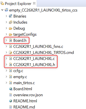
Generally, the Board source file are the same for all TI Driver examples for a given board.
Quiz
Does SysConfig change the runtime usage of TI Drivers?
Lab: Getting started
For this lab, we are going to import the Empty example from the
examples\rtos\<board>\drivers\empty directory. We'll do the following things in
the below tasks:
- Investigate the .syscfg file
- Configure the
Displaymodule in SysConfig - Configure the
Watchdogmodule in SysConfig - Add a button via SysConfig that will stop the tickling/feeding of the Watchdog timer.
The below steps will use simplelink_cc32xx_sdk along with the CC3235S_LAUNCHXL LaunchPad board. So some of the pictures/directory names/line numbers/sizes/etc. might be slightly different if you are using a different board or version.
Task 1 - Importing an Example
Start your Desktop CCS and import the TI-RTOS7 empty project from your
SimpleLink SDK.
Task 2 - Verifying the Example Works
To test that the software and hardware pre-requisites are fulfilled, we are going
to build and run the project before going forward. This will generate among others
the ti_drivers_config.c and ti_drivers_config.h files.
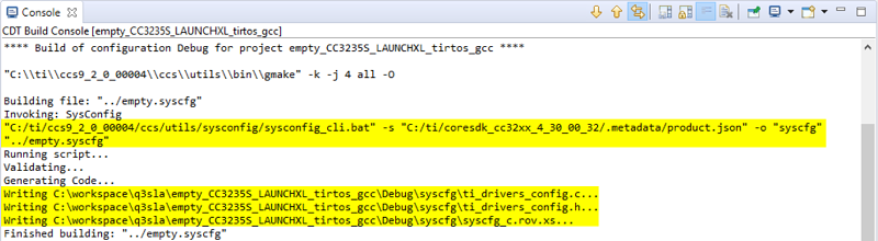
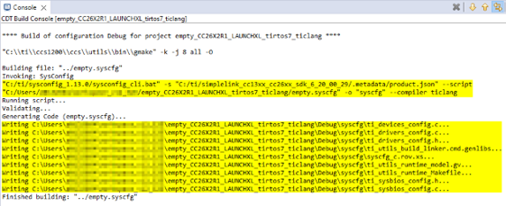
- Our first mission is to build the imported project. Select the project in
Project Explorer and choose
Project→Build Projectfrom the menu. Notice in the beginning of the application project build log that SysConfig generates theti_drivers_config.candti_drivers_config.hfiles (which are now in theDebug/syscfgdirectory).
- When the project is built, we are going to make sure that the hardware and
debugger work.
- Make sure the target is connected to the computer via the appropriate USB cable.
- To start debugging, select
Run→Debug, or press F11.
- When the download is finished, press F8 or the green play icon to run.
- You should see an LED toggle every second. Here is the code for the toggling
in
empty.c. Remember the constantCONFIG_GPIO_LED_0! We'll see where it comes from in the next step...while (1) { sleep(time); GPIO_toggle(CONFIG_GPIO_LED_0); }empty :: main()
Quiz
ti_drivers_config.c and ti_drivers_config.h are the only files ever generated by SysConfig?
Task 3 - Exploring SysConfig (Software)
Now that we've confirmed the setup is working, now let's actually look at the
SysConfig GUI Tool in CCS. We'll see where the CONFIG_GPIO_LED_0 constant was
defined and how the GPIO configuration was done.
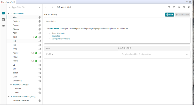
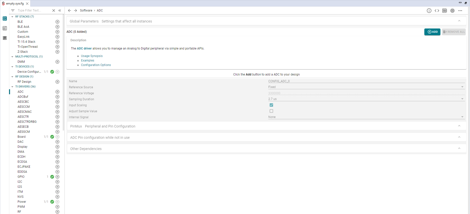
- Double-click the
empty.syscfgfile in the Project Explorer. After a couple seconds you should see this window:
- Let's look at a preview of the TI Driver configuration code that is going to
be generated by the
empty.syscfgfile. Select the<>icon on the top right of the SysConfig GUI. Note: all SysConfig generated files can be previewed here. For example thesyscfg_c.rov.xsfile is generated for viewing non-TI-RTOS modules in Runtime Object View andti_ndk_config.cfile for MSP432E4 Networking configuration.
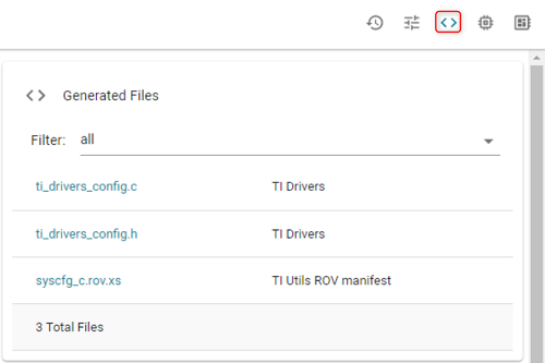
Click the ti_drivers_config.c file. This opens the preview of the generated
ti_drivers_config.c. In later tasks in this lab, you'll see this file updated as we change the TI Driver configuration. As you look at theti_drivers_config.c, you'll notice it is rather empty (as expected...the project is called Empty after all). Let's look at a couple key items in this file.- Generation Disclaimer: At the top, you'll see the disclaimer to not modify this file since it is generated. Any changes made to this file will be wiped out when it is re-generated. We'll show how to modify these generated files later on in this lab. (Spoiler...)
- Configuration of the LED: The configuration for the LED that this example uses.
As changes are made, green shading denotes additions and red shading denotes removed items (we'll see this in action later).
Device/Board Specific
Since the low level driver configuration is device/board specific, if you are using a different device or board, your generated
ti_drivers_config.cwill have different names for the constants and data structures than shown here.
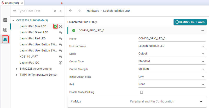
Select the GPIO module in the Software view. Here is the configuration for the LED that the example uses.
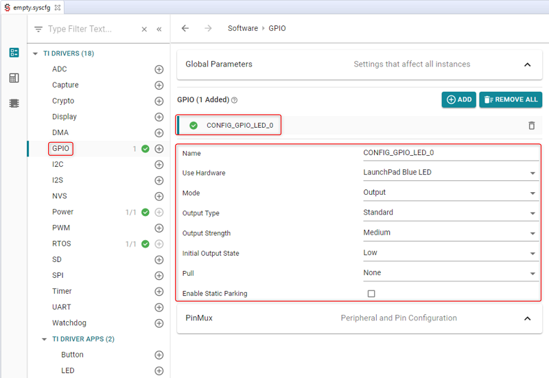
Where did the LaunchPad Blue LED in the Use Hardware field in the above picture come from?
Next section :)
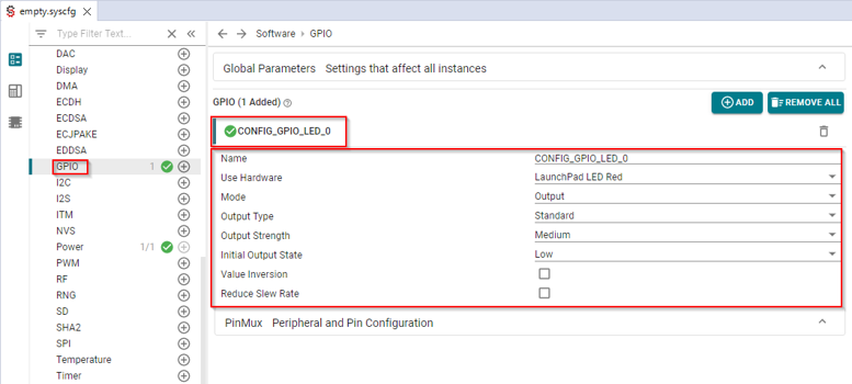
Where did the LaunchPad LED Red in the Use Hardware field in the above picture come from?
Next section :)
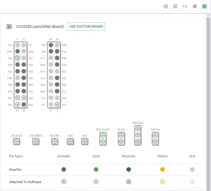
Use the board view to see which pins of the LaunchPad are used
This view can also be used to configure the project for a custom board (see button "Use Custom Board") and for board or device migration (see button "switch").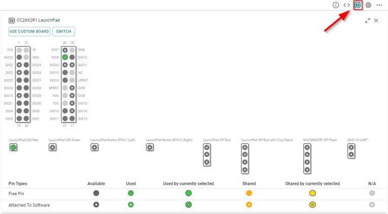
Use the device view to see which pins of the device are used.
This view can also be used for board or device migration (see button "switch").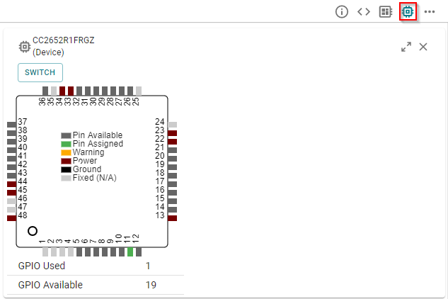
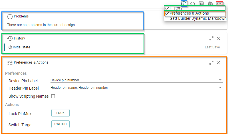
Display other useful views such as the Problems, History or Preferences & Actions. Note: the buttons to display all these views might be hidden. If so, click the "More Views" button (i.e. the three dots button) to find them.
Quiz
We've still not really answered where CONFIG_GPIO_LED_0 is defined. We see it in the GPIO configuration in the GUI, but where is the actual source code for it!
Task 4 - Exploring SysConfig (Hardware)
- Select the Hardware view. The hardware components on this LaunchPad are defined under this section.
You can see that the LaunchPad Blue LED is
currently being used (green check-mark) and the software configuration of it.
On the other hand, you can see that the green and red LEDs are not currently
in use.
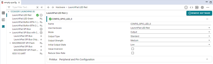
You can see that the LaunchPad LED Red is
currently being used (green check-mark) and the software configuration of it.
On the other hand, you can see that the LED green and the buttons are not currently
in use.
Custom Hardware
SysConfig supports all the SimpleLink LaunchPads and many BoosterPacks. Documentation can be found here.
Task 5 - Output via the Display Module
Let's start using SysConfig to configure new things! First let's add a
Display_printf to see output via the UART. All SimpleLink LaunchPads have a
back-channel UART via the emulation USB cable.
Have the
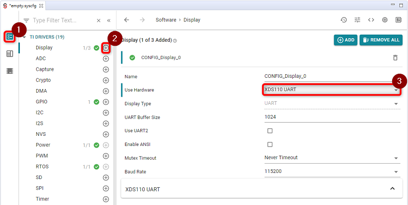
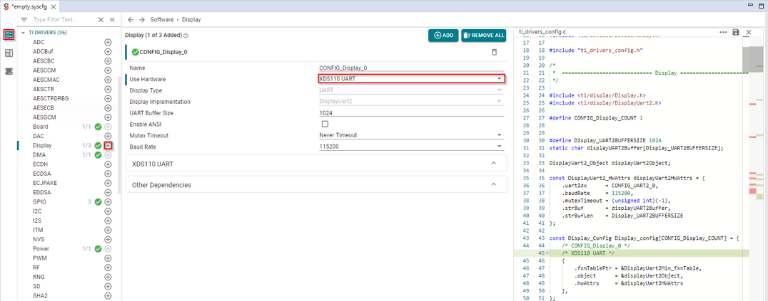
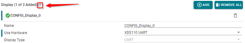
ti_drivers_config.cpreview open in SysConfig. We can see theDisplaysource code configuration get added when you do the next step!In SysConfig, go back to the Software view, click the + icon next to the Display module and then select
XDS110 UARTin the Use Hardware drop-down and save the file. When you hit the + icon, you'll see theti_drivers_config.cfile change in the preview.
Now let's add the usage of the
Displaymodule into theempty.cfile.Add Display.h header
#include <ti/display/Display.h>empty.c Add in with other #includes
Add initialization of the Display instance. Also add a count variable that will be used in the
Display_printf.Display_init(); Display_Handle hSerial = Display_open(Display_Type_UART, NULL); uint32_t count = 0;empty.c :: mainThread() in the function before the
whileloop.Add the
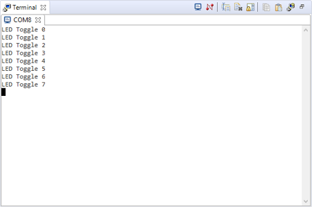
Display_printcall into thewhileloop.while (1) { sleep(time); GPIO_toggle(CONFIG_GPIO_LED_0); Display_printf(hSerial, 1, 0, "LED Toggle %d", count++); }empty.c :: mainThread() the new while loop
Rebuild/load/run the application.
Open your favorite terminal application (e.g. PuTTY, CCS Terminal). You'll probably need to use Device Manager (if using Windows) to determine the correct COM port.
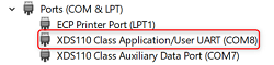
with the following settings (note your COM port will most likely be different!).
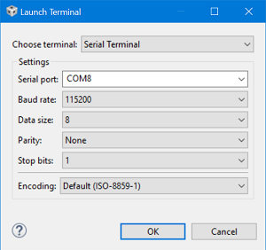
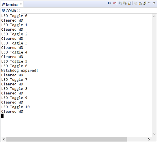
You should see the output in the terminal session
The TI Drivers and Display module are covered in the <SimpleLink_SDK_Install_Dir>/docs/tidrivers/tidriversAPIs.html
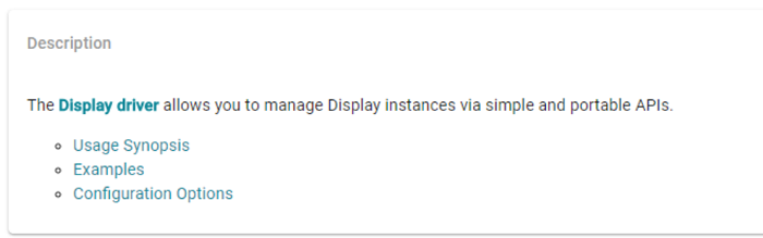
file. You can get to a specific module via SysConfig. In the module view, click
the ?
Here is the description text and link for the Display module.
Additionally, if the hover over a configuration field, you generally will get more information about the field.
Task 6 - Add Watchdog
Most production applications include some type of Watchdog timer to help in unexpected behavior. We are going to add a Watchdog timer into the application. We'll keep it simple and not have it restart the application. It will only set a flag to denote that it has expired.
In SysConfig, click the + icon next to the
Watchdogmodule and then change the Period to 1500. Remember to save the file!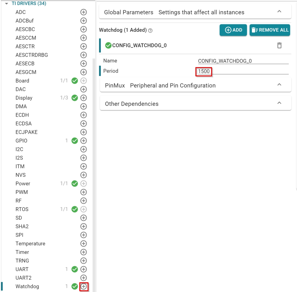
Now let's add the usage of the
Watchdogmodule into theempty.cfile.Add header and some global variables
#include <ti/drivers/Watchdog.h>
volatile uint8_t serviceFlag = 1;
volatile uint8_t watchdogExpired = 0;
Watchdog_Handle watchdogHandle;
empty.c Add in with other #includes
Open the Watchdog peripheral
Watchdog_init(); Watchdog_Params params; Watchdog_Params_init(¶ms); params.callbackFxn = (Watchdog_Callback)watchdogCallback; params.resetMode = Watchdog_RESET_OFF; watchdogHandle = Watchdog_open(CONFIG_WATCHDOG_0, ¶ms); if (watchdogHandle == NULL) { /* Error opening Watchdog */ while (1); }empty.c :: mainThread() in the function before the
whileloop.Add the Watchdog callback. Note this function is specified in the Watchdog parameters above.
void watchdogCallback(uintptr_t unused)
{
  /* Clear watchdog interrupt flag */
  Watchdog_clear(watchdogHandle);
  watchdogExpired = 1;
  serviceFlag = 1;
}
empty.c above the mainThread function
Add the tickling/feeding of the Watchdog timer and debug output to show that the Watchdog timer expired in the while loop.
while (1) {
   sleep(time);
   GPIO_toggle(CONFIG_GPIO_LED_0);
   Display_printf(hSerial, 1, 0, "LED Toggle %d", count++);

   if (watchdogExpired) {
     Display_printf(hSerial, 1, 0, "Watchdog expired!");
     watchdogExpired = 0;
   }

   if (serviceFlag) {
     Watchdog_clear(watchdogHandle);
     Display_printf(hSerial, 1, 0, "Cleared WD");
   }
}
empty.c modified while loop
Rebuild/load/run the application.
Quiz
Why does the Watchdog never expire?
Watchdog configuration vary per device
Please consult Watchdog API reference and TRM for more details on the Watchdog for your device.
Task 7 - Add a button
Let's add a button to the application. When pressed, it will disable the
tickling/feeding of the Watchdog in the while loop.
Have the
ti_drivers_config.hpreview open in SysConfig. We can see the name of the button get modified as we change it!In SysConfig, let's add a button via the Hardware view instead of Software.
Select Hardware and click the + icon next to LaunchPad User Button SW2 (Left). Make sure to select GPIO.
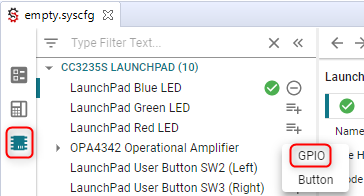
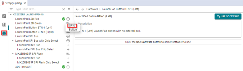
Select Hardware and click the + icon next to LaunchPad Button BTN-1 (Left). Make sure to select GPIO.
Configure the GPIO used by the button
- Change the name of the constant to
WDBUTTON. Note: you'll see the name change in theti_drivers_config.hpreview window. - Select
Pull Upfor the Pull field andFalling Edgefor the Interrupt Trigger. Finally, set the button callback to
stopTicklingWatchdog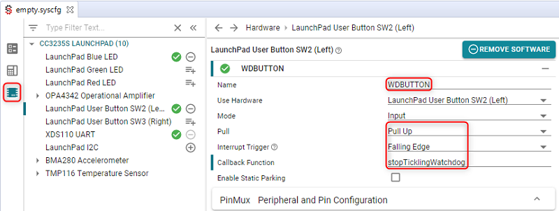
- Change the name of the constant to
WDBUTTON. Note: you'll see the name change in theti_drivers_config.hpreview window. - Select
Nonefor the Pull field andFalling Edgefor the Interrupt Trigger. Finally, set the button callback to
stopTicklingWatchdog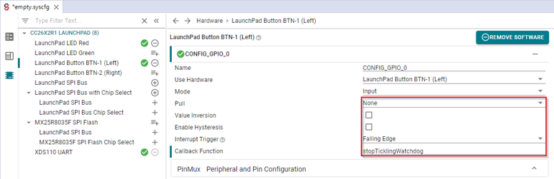
- Change the name of the constant to
Now let's add the usage of the button into the
empty.cfile.Add the enabling of the callback. Note the name of the constant is from the SysConfig Name setting.
GPIO_enableInt(WDBUTTON);empty.c after the
GPIO_setConfigAdd the callback (note the name must match the SysConfig Callback Function setting).
void stopTicklingWatchdog(uint_least8_t index)
{
   serviceFlag = 0;
}
empty.c above the mainThread function
Rebuild/load/run the application.
Hit BTN-1 (or whatever button you specify) refer to Board.html for details. Your output should denote that the Watchdog did expire.
Quiz
Click on the "Show Board" button.
What is this for?
Quiz
Click on the "Reserve Peripherals" button.
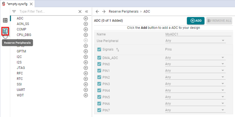
What is this used for?
(Optional) Task 8 - How to "disable" SysConfig
Great! You have your configuration setup, but you'd like to add some comments in
the ti_drivers_config.c or ti_drivers_config.h files or simply "freeze" them.
How do you do this?
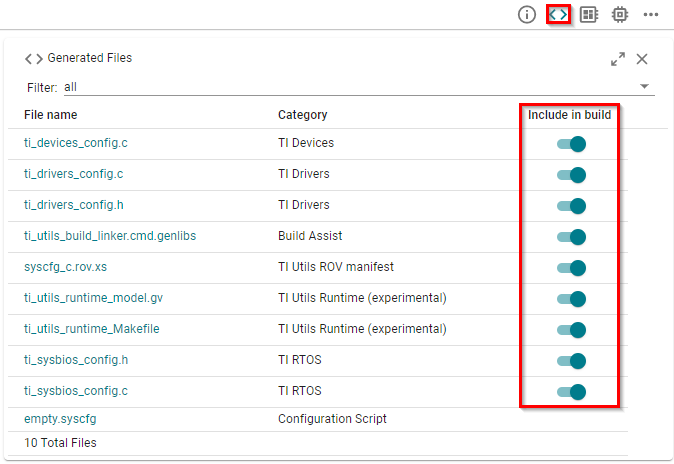
SysConfig provides a way to exclude from the generation some of the files.
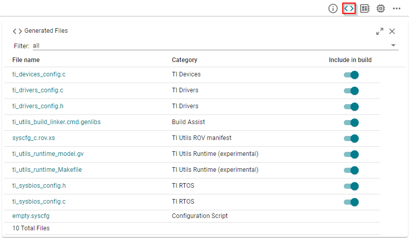
Select the
<>icon on the top right of the SysConfig GUI.Files can be included or excluded from the generation using the Include in build button.
Replace excluded files
If you decide to exclude a file, SysConfig will not generate it. So you have to make sure to provide this file to the toolchain anyway (otherwise you will face build issues).
We recommend you leverage the files initially generated by SysConfig as baseline. The steps here after guide you to do so.
Copy the
*.cand*.hfiles you have excluded from build from Debug/syscfg into your project's root directory. Don't try to copy them from the Generated Sources directory. This is just a short-cut to view the files.If you have exluded
ti_utils_build_linker.cmd.genlibs, copyti_utils_build_linker.cmd.genlibsinto your project's root directory. Additionally, modify the Project Properties → Build → ARM Linker → File Search Path to include${PROJECT_LOC}. This is needed to pickup the new location of the generated linker file.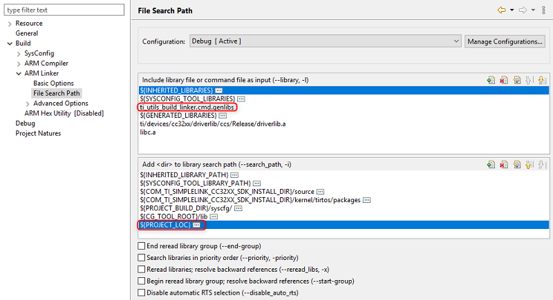
If you have exluded it, copy syscfg_c.rov.xs into your project's root directory. This file is needed for some modules to show up in
Runtime Object View (ROV).Rebuild/load/run the application. It will behave the same except the files will not be re-generated.
(Optional) Task 9 - Moving to a new SDK Version
You have everything configured via SysConfig with a specific version of the SDK and the application is working well...great! What happens when you move to a newer version of the SDK? Here are the high-level steps that you need to do:
Install the new SDK and have CCS discover it.
Move the working application to the new SDK (refer to the SimpleLink User Guide for details on how to do this).
Rebuild the application. This will regenerate the files based on the new content in the new SDK. Please note that SysConfig really has two pieces
- The SysConfig GUI/cmdline tool (available in CCS or as a stand-alone tool).
- The meta-data in the SimpleLink SDKs that the SysConfig tool reads to build
up the views (e.g. the
Displaymodule in the SDK specifies that it supports, UART, Console and LCD).
This work is licensed under a Creative Commons Attribution-NonCommercial-NoDerivatives 4.0 International License.