Introduction
Z-Stack is a component of the SimpleLink CC13xx / CC26xx Software Development Kit and is a complete Zigbee 3.0 software solution.
The intention of this lab is to get developers started with Z-Stack by showing how to get a simple Zigbee network up and running with a Coordinator and an End Device, as well as create binds between these two devices.
Task 1: Building and loading the sample applications
Task 2 (optional): Setting up a packet sniffer to analyze over-the-air traffic
Task 3: Accessing the Sample Application UI with PuTTY
Task 4: Setting up the Zigbee network and creating binds
Task 5: Testing the Sample Application features
Technical support
For any questions you may have, please refer to the TI Zigbee & Thread E2E Forum.
Prerequisites
Background
- Familiarity with the Zigbee 3.0 specification
- More information about the changes in Zigbee 3.0 compared to older specifications can be found in SWRA615
- Basic CCS knowledge
- Some basic familiarity with embedded programming.
Software
- Code Composer Studio (latest version) with support for CC13xx/CC26xx devices
- SimpleLink CC13xx / CC26xx SDK (latest)
- Uniflash
- PuTTY
- Ubiqua Protocol Analyzer (optional for packet sniffing)
- Wireshark (optional for packet sniffing)
- TI Packet Sniffer (optional for packet sniffing with CC2531EMK)
- TI Packet Sniffer 2 (optional for packet sniffing with LaunchPads)
Hardware
- 2 x Zigbee-capable SimpleLink LaunchPads for running sample applications, review the SDK Release Notes for more information.
- 1 x LaunchPad or CC2531EMK for packet sniffing (optional)
- Micro USB Cables
- 1 x LaunchPad or CC2531EMK for packet sniffing (optional)
- Micro USB cables
Recommended Reading
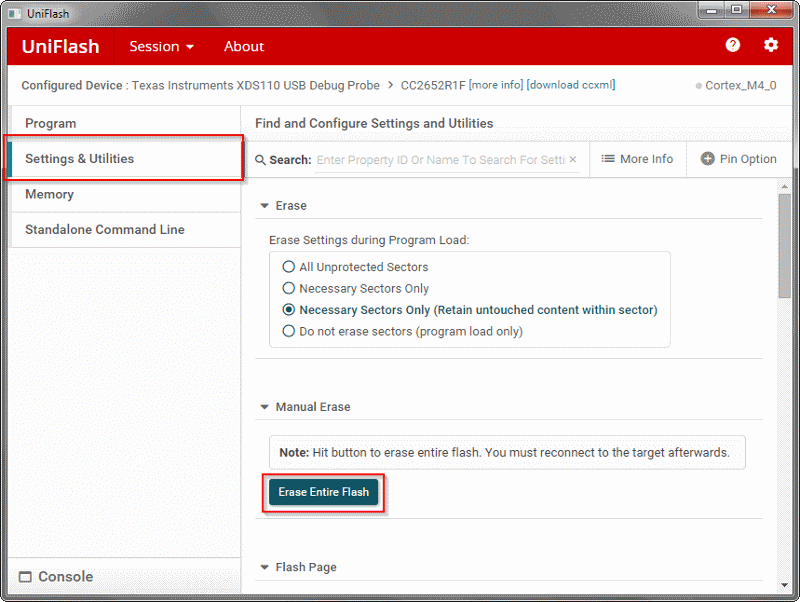
Task 0: Erase the Flash Memory on your LaunchPads
Make sure that the flash memory has been completely erased on each of your LaunchPads before flashing any Zigbee projects. This can be done in Uniflash, here:
Task 1: Building and loading the sample applications
In CCS, go to
File > Import > C/C++ > CCS Projectsand underSelect search-directory:select the following search path for the Light Coordinator:C:\ti\simplelink_cc13xx_cc26xx_<version>\examples\rtos\<LaunchPad variant>\zstack\zc_light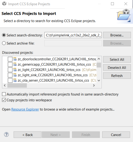
Locate the Z-Stack module of
zc_light.syscfg, this will allow us to change many network parameters for our Coordinator device. Here you can configure parameters from theZ-Stackmodule such as:Radio > Primary Channels, the channel list bitmask for which we will form our network on or attempt to join a network on if we are a ZR/ZED. Default is channel 11 only.Network > PAN ID, the PAN ID of the network we will form or attempt to join if we are a ZR/ZED . Default is 0xFFFF, which will randomize the PAN ID.Network > Default Network Key, the default NWK layer security key that is distributed after new devices join or used by default by joining devices. The default is all 0x00, which will randomize the NWK key.
Once the project has been built, these settings are defined as macros inside ofdefault/sysconfig/ti_zstack_config.h. More information about these configuration parameters can be found in the TI Z-Stack User's Guide under the Network Configuration section.After you are satisfied with your network configuration parameters, first Build the project by going to
Project > Build Project. Once this has completed, make sure you have a LaunchPad connected to your PC and go toRun > Debugto flash the program on your LaunchPad. If you have multiple LaunchPads connected to your PC, CCS may prompt you to select one of the connected LaunchPads via the box below: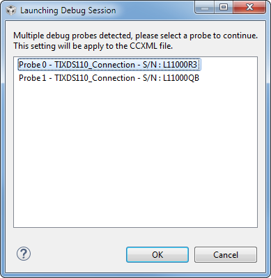
The selected LaunchPad's serial number will be assigned to this project workspace so future program launches will automatically attempt to select this LaunchPad first if it is plugged in. More information about debugging with multiple probes can be found here.
Repeat steps 1 through 3, but using the Switch End Device project (zed_sw)
Task 2 (optional): Setting up a packet sniffer
Whenever doing any sort of Zigbee network development, it is highly recommended to use an over-the-air packet sniffing tool to help understand what is happening in your network. TI recommends two different packet sniffing solutions:
- Ubiqua Protocol Analyzer, a powerful subscription-based network analysis tool developed by Ubilogix capable of decoding many IEEE 802.15.4 protocols such as Zigbee, Thread, and 6LoWPAN, available here.
Wireshark 3.0.X, a free and open-source packet sniffer solution available here, which can work when coupled with TI Packet Sniffer 2 software.
More information about how to set up a packet sniffer can be found in the TI Z-Stack User's Guide, under the Packet Sniffer section.
Task 3: Accessing the Sample Application User Interface with PuTTY
The Z-Stack Sample Applications provide the user a variety of run-time configuration options and application actions which are available through the UI. To access the UI, we will need to use a terminal emulator program like PuTTY.
Note
Some terminal emulator programs like the CCS terminal or Tera Term will not work properly with the User Interface due to to how the "Form Feed/New Page" character is interpreted by each program (ASCII 0x0C). PuTTY is known to work with the UI properly in its default configuration.
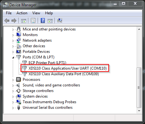
Determine which COM port your LaunchPad is on. There are various ways to do this, but one way is to open Windows Device Manager and go to Ports. We are interested in the Application/User UART connection:
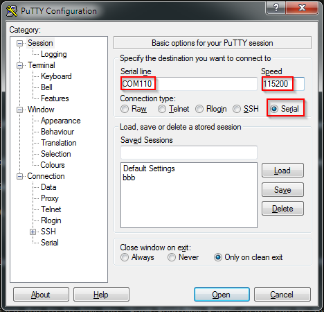
Open PuTTY and select Serial connection type, enter your COM Port, and use a speed of 115200 Baud.
You may need to press the 'Reset' key on the LaunchPad at this point to get the UI to appear in PuTTY after your session is connected.
You can navigate through the User Interface using arrow keys and make selections using Enter. For more information about the User Interface, check the TI Z-Stack User's Guide under the Common User Interface section.
Task 4: Setting up the Zigbee network and creating binds
Now it's time to form a simple Zigbee network with a Coordinator and one End Device.
1. Form and open the network with the Coordinator
Zigbee 3.0 network commissioning follows the behavior as described by the Base Device Behavior (BDB) Specification, which is available from the Connectivity Standards Alliance website. In short, there are 3 commissioning modes that are useful for us in this lab:
- Network Formation
- Network Steering
- Finding & Binding (F&B)
The BDB commissioning mode variable is a bitmask, which means we can start the BDB commissioning state machine with multiple commissioning modes selected. By default, for a given device type, all valid commissioning modes for that device type are used. As an example, when a factory-new Coordinator device begins BDB commissioning, it will:
- Form a new network on the selected channel (Network Formation)
- Open the network for new devices to join (Network Steering)
- Look for devices in the network that have matching Zigbee clusters to create binds with (F&B)
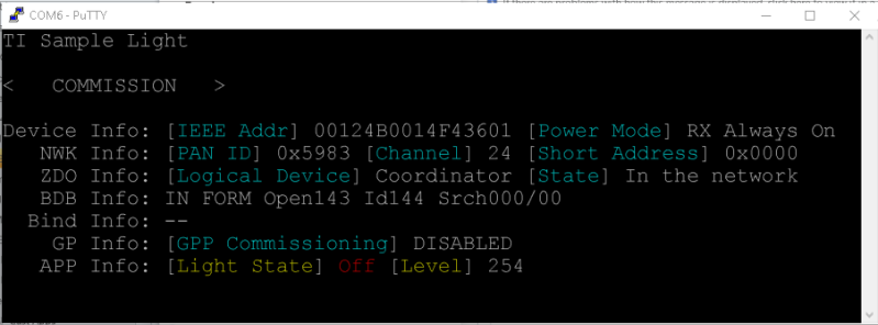
To do this action with the Sample Application UI, navigate to the < COMMISSION > screen and press Enter. Alternatively, pressing BTN-1 on your LaunchPad accomplishes the same function.
2. Join our newly created network with the End Device
Similar to the Coordinator, we will run BDB commissioning with all valid commissioning modes active. For a factory-new End Device, BDB commissioning will do the following:
- Network Formation is not valid for End Devices (ignored as they cannot form their own networks)
- Search for networks that are open and have good signal integrity, then attempt to join the best-suited network (Network Steering)
- If it joins successfully, look for devices in the network that have matching Zigbee clusters to create binds with (F&B)
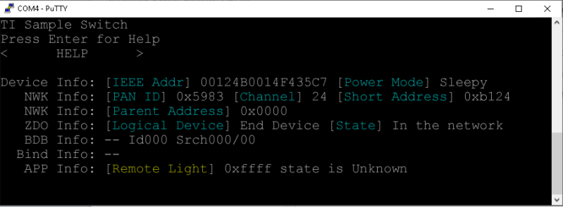
To do this action with the Sample Application UI, navigate to the < COMMISSION > screen and press Enter. Alternatively, pressing BTN-1 on your LaunchPad accomplishes the same function.
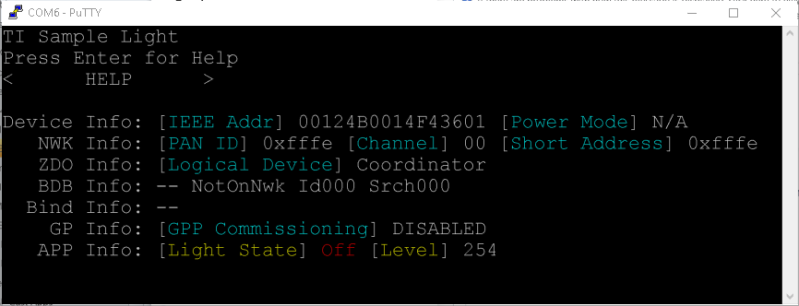
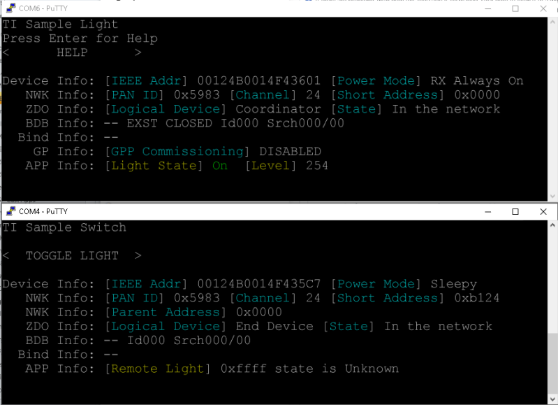
3. Check the network information screen of both of our devices
The common UI screen provides various information about our current network like the PAN ID, NWK address, and channel.
4. Observe the sniffer log to see the joining process over-the-air
Below is a screenshot of Ubiqua Protocol Analyzer after capturing the over-the-air traffic of the Switch ZED joining the Light ZC.
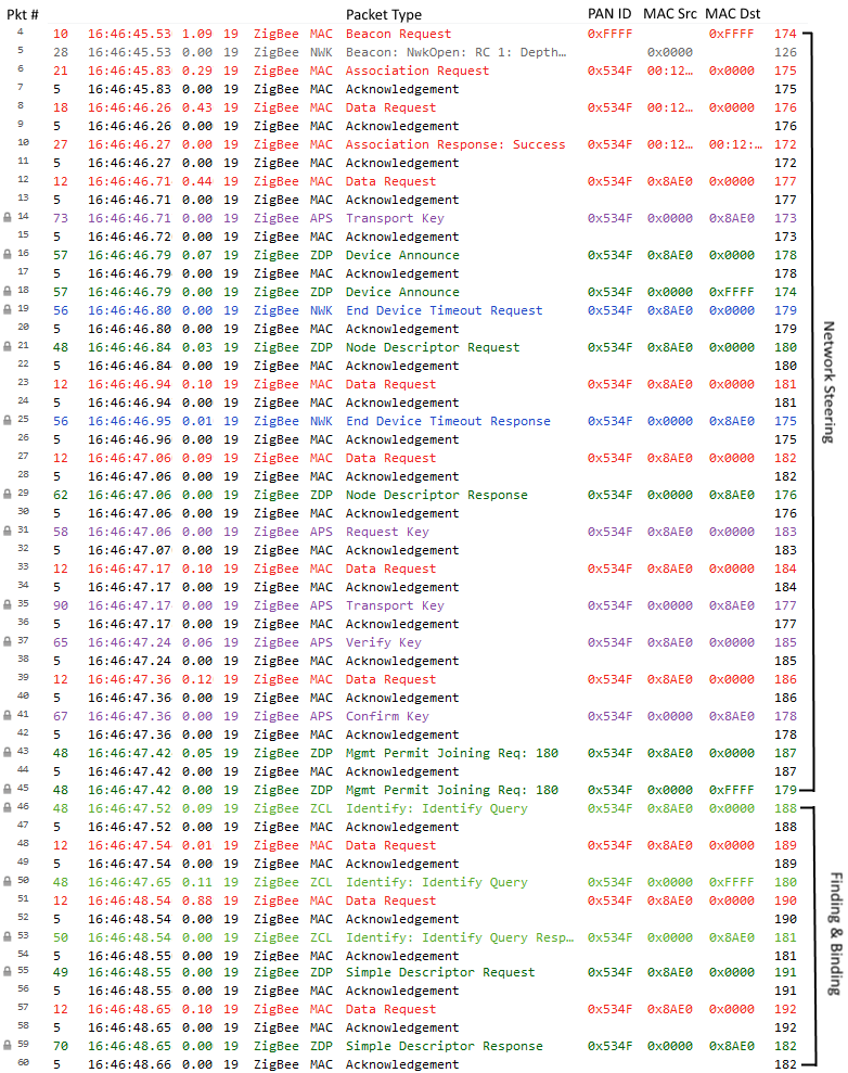
Packets #4 through #45 are the Network Steering packets between the devices:
- #4: Beacon Request from ZED
- #5: Beacon Response from ZC, status Nwk Open
- #6-11: MAC layer association, ZED = 0x534F, ZC = 0x0000
- #14: Zigbee NWK authentication
- #16,18: ZED Device Announce Broadcast since it is a new network device
- #19,25: End Device Timeout handshake (see Zigbee PRO Specification)
- #21,29: Node Descriptor handshake (see Zigbee PRO Specification)
- #31-41: TC Link Key Update procedure (see Zigbee PRO Specification)
- #43,45: Permit Join Broadcast to open network for joining for 180 seconds
Packets #46 through #60 are the Finding & Binding packets between the devices:
- #46: Since the ZED is in F&B mode, it periodically sends a Identify Query Request
- In this case, the ZED is the F&B Initiator Device and the ZC is the F&B Target Device. Refer to the Zigbee Application Architecture document from the Connectivity Standards Alliance for more information about F&B Initiator/Target assignments.
- #50: Identify Query Request is rebroadcasted by ZC, ZED's parent device (see Zigbee PRO Specification for more details)
- #53: Identify Query Response from ZC
- This tells the F&B initiator which endpoint on the ZC is currently the F&B target
- #55: Simple Descriptor Request from ZED to ZC
- #59: Simple Descriptor Response from ZC to ZED
- This tells the ZED which clusters the ZC's F&B target endpoint supports, and the ZED will create local binds based on matching cluster(s). In this case, the ZED will create a bind from its Switch endpoint to the Light endpoint (the matching cluster is the On/Off Cluster), which means the Switch can now control the Light.
Task 5: Testing the Sample Application features
Now that we finally have the network set up, we can test out the sample application commands. In this particular case, we can toggle the Light on and off using the Switch.
For both applications, scroll to the < APP MENU > screen in the Sample Application UI and press Enter. For the Light this will take you to a screen with the current Level and State of the Light. For the Switch this will take to you to a screen where you can toggle the Light by pressing Enter. When you press Enter on the < TOGGLE LIGHT> screen on the Switch, it will toggle the Red LED on the Light LaunchPad, and it will also update the Sample Application UI with the current state of the Light. This same action can be performed by pressing BTN-2 on your Switch LaunchPad.
Note
To perform a factory reset on either device, hold down the BTN-2 button on the LaunchPad while restarting the device (power cycle or pressing the reset button). This will erase all NV memory which contains network information such as binding tables, PanID, network keys, etc.
Next Recommended Zigbee SimpleLink Academy Labs
- Designing a Custom Zigbee 3.0-Certifiable Product Using SampleApp
- Zigbee Fundamental Project Development
- Zigbee Security Features
- Zigbee ZCL: Keepalive Poll Control Cluster and Groups/Scenes
This work is licensed under a Creative Commons Attribution-NonCommercial-NoDerivatives 4.0 International License.