Introduction
This workshop offers a first experience in the data_stream example project.
The purpose is to have a better understanding of the device's functionalities.
Here it will dive into echoing a value entered by the user and plenty of features around this principle.
This project is the perfect entrance for UART over Bluetooth® LE.
It can also easily handle data transfer and can be used for data streaming.
Prerequisites
Hardware
- SimpleLink™ CC2340RX LaunchPad™ Target
- SimpleLink™ Modular LaunchPad™ Emulator
- USB cable
- SmartPhone or Tablet with a GATT Table viewer application installed (such as TI SimpleLink Connect app)
Note
Here are links to the TI SimpleLink Connect app
TI SimpleLink Connect on Google App Store
Find the QR code to download the app below:

Software
- CCS version 12.3 and newer
- SIMPLELINK-LOWPOWER-F3-SDK SimpleLink™ Software Development Kit
Readings
- SDK User's Guide: PATH =
C:/ti/simplelink_lowpower_f3_sdk_x_xx_xx_xx_eng/docs/ble5stack/ble_user_guide/
html/ble-stack-5.x-guide/ble-stack-5-index-cc23xx.html
. You should particularly have a look on the Generic Access Profile (GAP) and Generic Attribute Profile (GATT) sections, it will help you to understand a bit more about the theory behind Bluetooth™ Low Energy protocol.
Agenda
In this training, we will discuss how to prepare the data_stream example for custom development.
1. Discuss how to set up the environment and how it works
2. A brief explanation of the GATT concepts
3. Working principle of the project
4. How to change basic device configurations
5. Some help to customize your project
Preparation
Initial Setup
If your system is already setup skip this part and go directly to the first connection using GATT table.
All the collaterals are available on TI website.
Download and Install the SDK found in the software section above.
Follow the Quick Start Guide found inside the BLE5 Stack User Guide
PATH = C:/ti/simplelink_lowpower_f3_sdk_x_xx_xx_xx_eng/docs/ble5stack/ble_user_guide/html/quickstart-guide/quickstart-intro-cc23xx.html.
Setting up the Serial terminal
Identify the COM port used by the SimpleLink™ CC2340RX LaunchPad™.
- Disconnect all the LaunchPads™ you may have connected to your computer leaving only the SimpleLink™ CC2340RX LaunchPad™.
- Open the Device Manager. You can do so by typing Device Manager in the Windows start menu.
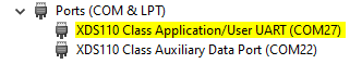
- In the Device manager, find the menu Ports (COM & LPT) and unroll it.
Observe the line called XDS110 Class Application/User UART. Note down the COM port this interface is using. In my case (see below), the COM port used is called COM27.
Open a serial terminal to observe the COM port identified previously. For this example, I'll show how to use the serial port provided by CCS, but you can use your favorite serial terminal provider.
- On CSS, click on
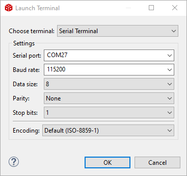
View→Terminal, or use the shortcutCtrl+Alt+Shift+T. - A pop-up allowing you to configure the terminal will appear. Select the following settings:
- Choose Terminal: Serial Terminal
- Serial Port: The serial port identified before (COM27 for me)
- Baud rate: 115200
- Data size: 8
- Parity: None
- Stop bits: 1
- Encoding: Default (ISO-8859-1)
- Once done, click
OK. - Display the Command Input Field by clicking on
Toggle Command Input Field(see label 1), then clear the terminal content by clicking onClear Terminal(see label 2)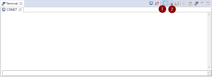
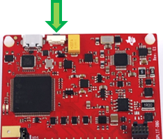
- To finish, reset the SimpleLink™ CC2340RX LaunchPad™ by pressing the reset
button on the emulator.
- On CSS, click on
Flash the CC2340 with the unmodified code
At this point open CCS, create a new Workspace (don't forget to add the workspace variable
FREERTOS_INSTALL_DIR) and import the data_stream project. Then build and flash the
code on the device.
If you need help for this, make sure to review Quick Start Guide!
Once the LaunchPad is ready, the green LED (labeled Green DIO15) turns on.
To test the Bluetooth LE communication, a connection should be formed between
a central device and the CC2340RX running the data_stream example.
An easy way to do this is by using a Smartphone or Tablet device with a GATT Table viewer application.
With one of these applications, one should be able to scan and connect to the device as well
as interact with the characteristics present in the project.
More details on the way of testing the Bluetooth communication between the CC2340 and a smartphone are provided in the next sections.
Introduction of the GATT concepts
This section will provide a quick introduction of the GATT the concepts you should know to handle properly this example. Feel free to skip this section if you are already familiar with these concepts.
Attributes and Characteristics
An Attribute is the smallest addressable unit of data used by ATT and GATT.
It is addressed via a 16-bit handle, it has a type, which is an UUID that can be
16, 32 or 128 bits long, and it has a data field which can be up to 512 bytes
long. Note that all 32-bit UUIDs should be converted to 128-bit before sending
over the ATT protocol.
Summarized, the Attribute Protocol defines an attribute to consist of
- Handle – The 'address' of the Attribute when accessed via the Attribute Protocol
- UUID – The 'type' of the Attribute
- Value – Array of bytes interpreted differently depending on the UUID (type).
| Handle | UUID | Value |
|---|---|---|
| 16 bits | 16 or 128 bits | 1 to 512 bytes. |
Several of these attributes are needed to define a Characteristic. A
Characteristic always consists of at least a Value attribute and a
Declaration attribute. The meaning of the Value attribute is defined in the
Profile. The Declaration always comes before the value attribute and
describes whether the value attribute can be read or written, contains the UUID
of the Characteristic and the handle of the Characteristic Value's attribute.
Other attributes of a characteristic can give a description of the
characteristic in string format, or describe how the Value should be
interpreted, or configure whether the GATT Server may send Notifications
about value changes. These are called Descriptors.
Handle
In the TI BLE5-Stack, unique handles are assigned starting from 1 when the attribute is registered with the GATT Server. This usually happens during initialization. If the firmware doesn't change, the handle is always the same.
UUID
The UUID tells a peer device how the value
of the Attribute should be interpreted. For example, 0x2803 is defined
in the specification to mean Characteristic Declaration.
Multiple attributes may share the same UUID so handles are needed to identify
a particular attribute instance.
Warning
Proprietary (non-SIG-adopted) services must use 128-bit UUIDs to avoid collision, unless a 16- or 32-bit UUID is acquired from the SIG.
First connection using GATT table
Data_stream Operational Principles
The following steps will showcase how to connect, write and receive a value by using the TI SimpleLink Connect application on Android OS. Note that these steps are almost the same for iOS smartphone.
Scan and locate the Data Stream device
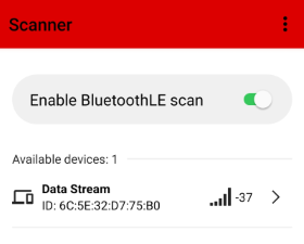
Find the right device
Add a filter on the proximity of the device by pressing the settings menu (three dots on the top right-hand corner) or swapping to the right. Then activate the RSSI filter and update its value.
This feature will help you to filter out any faraway devices and make it easier to find the
data_streamdevice in a crowded BLE environment.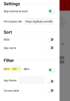
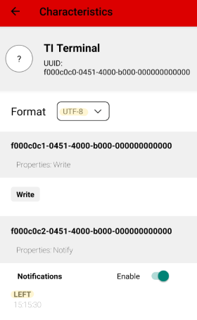
Connect to the Data Stream device by tapping on the arrow and expand the
TI Terminaltab which has the UUID0xF000C0C0-0451-4000-B000-000000000000Remark
A common practice is to choose a base UUID for the custom service and then increment the 3rd and 4th Most Significant Bytes (MSB) within the UUID of each included characteristic. Here the 3rd and 4th MSB is set to
0xC0C0for the base UUID. The characteristic UUIDs are then formed by incrementing 0xC0C0. To improve the readability of this lab, we may only mention the 3rd and 4th MSB of the UUIDs.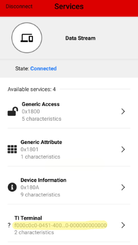
First, on the characteristic
Server Datawhich has the UUID0xC0C2, turn the switch on to enable Bluetooth Low Energy notification. This button will turn green after the notifications have been enabled.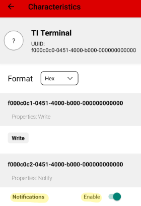
Then, on Characteristic
Write Datawhich has the UUID0xC0C1, press the Write button to write the string value to echo. Note to change the format in the combobox. To write an ASCII string you have to change it to UTF-8. A string should be written and theOKbutton should be pressed. This will write the data to the characteristic.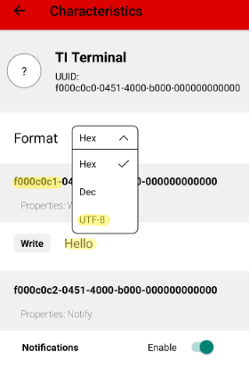
At this point the green led should be turn off and the red one turn on, to indicate that the data has been received.
- The value pop in the
Server Datacharacteristic section as an echo of theWrite Datacharacteristic. The response is sensitive case, a message in capital letters will be in small letters in response and vice versa.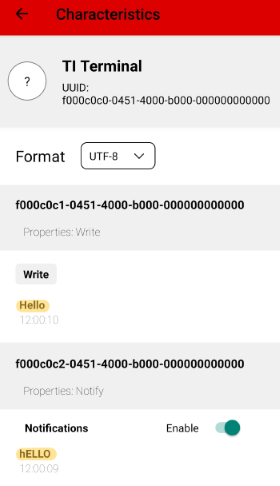
Remarks
If the string value exceed 20 characters, a second request is sent and two packets are visible in the notifications field. Thus, the led toggle twice.
To summarize, when we write to the characteristic, the SmartPhone device sends the data via Bluetooth LE to the SimpleLink™ CC2340RX LaunchPad™ which receives it, processes it, packages it, and sends it back to the SmartPhone to the other characteristic. Thus, data are transmitted both ways, from the SmartPhone to LaunchPad and vice-versa.
Changing device configurations
This section describes how to customize your device configurations:
- Change the Data Stream Service and Characteristics UUID - This is useful when the central expects specific UUIDs or you want to deploy the system with your own UUIDs.
Change UUIDs
This section will touch upon UUIDs and how to change them for your project.
Currently our Characteristic UUIDs for Data_stream Service, In Characteristic and Out Characteristic are as the following picture shows:

Remarks
In this guide, we'll consider this point of view for the inputs/outputs for the TI_BASE_UUID_128:
Data Stream Server Service UUID: 0xC0C0
Data In characteristic UUID: 0xC0C1
Data Out characteristic UUID: 0xC0C2
To change that we need first to modify the advertising UUID:
Open the
.syscfgfile inside the app folder of thedata_streamproject. ExpandRF Stacks Section→BLE→Broadcaster Configuration→Advertisement Set 1→Advertisement Data 1→UUID 0 (128-bit More)and change by an other UUIDfor this example
0x9ECADC240EE5A9E093F3A3B50100406E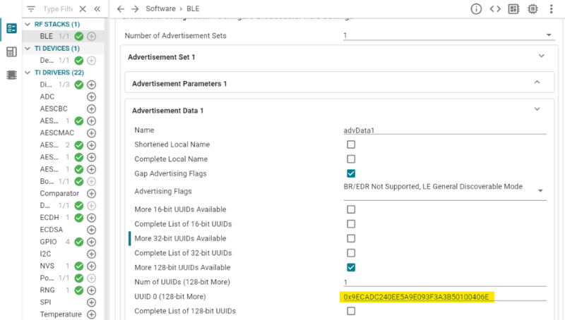
Then we need to do a copy of the
data_stream_server.cfile, as for the moment this file is aLinked File. Thus, to avoid to change all your future projects, as it will directly impact the roots of all your projects, we need to create a local copy of this file. To do so:- First, write down the location of the file by memorize its path:
- Open
data_stream_server.clocated incommon→Services→data_streamin your file project. - Right click to the file →
Properties→Resolved location, here is the path of your file.
- Open
- Delete the file
- Drag and drop the
data_stream_server.cfile from yourFile Explorerto the exact same location you deleted it once step before, but tick the copy option.
At this point you should see in the properties of your file that the
Typeof your file is no longer aLinked Filetype.- First, write down the location of the file by memorize its path:
Then we will change the UUID base, open
data_stream_server.c, at the beginning of the file add the following code in the CONSTANTS section and modify it with the UUID base we want for this example./// @brief Customer Base 128-bit UUID: 6E40XXXX-B5A3-F393-E0A9-E50E24DCCA9E #define CUSTOMER_BASE_UUID_128( uuid ) 0x9E, 0xCA, 0xDC, 0x24, 0x0E, 0xE5, 0xA9, 0xE0, \ 0x93, 0xF3, 0xA3, 0xB5, LO_UINT16( uuid ), HI_UINT16( uuid ), \ 0x40, 0x6E /// @brief GATT Custom UUID #define GATT_UUID_C(name, UUID) CONST uint8 name[ATT_UUID_SIZE] =\ {\ CUSTOMER_BASE_UUID_128(UUID)\ }Content to add to the CONSTANTS section of the
data_stream_server.cfileModify the LOCAL VARIABLES section with your GATT Custom new value by adding the
_Ccharacters at the end of the data name:GATT_UUID// Data Stream Server Service UUID: 0x0001 GATT_UUID_C( dss_serv_UUID, DSS_SERV_UUID ); // Data In Characteristic UUID: 0x0002 GATT_UUID_C( dss_dataIn_UUID, DSS_DATAIN_UUID ); // Data Out Characteristic UUID: 0x0003 GATT_UUID_C( dss_dataOut_UUID, DSS_DATAOUT_UUID );Content to modify to the LOCAL VARIABLES section of the
data_stream_server.cfileTo change the different UUID, create a copy of the
data_stream_server.hfile as the same way as we did on step 2 with thedata_stream_server.cfile.The
data_stream_server.hfile is located incommon→Services→data_streamin the project explorer.At the beggining of the file change the
#defines:DSS_SERV_UUIDDSS_DATAIN_UUIDDSS_DATAOUT_UUID/********************************************************************* * CONSTANTS */ // Service UUID #define DSS_SERV_UUID 0x0001 // Characteristic defines #define DSS_DATAIN_ID 0 #define DSS_DATAIN_UUID 0x0002 // Characteristic defines #define DSS_DATAOUT_ID 1 #define DSS_DATAOUT_UUID 0x0003Make sure to change the three lines with the right UUID part of the
data_stream_server.hfileNote
Don't forget to change the include of the
data_stream_server.h, it needs to point on your local copy.//#include <ti/bleapp/services/data_stream/data_stream_server.h> #include "data_stream_server.h" // change with this linechange this code in the INCLUDES section of the
data_strea_server.cfile
Test your changes
At this point you can build and flash the code on the device.
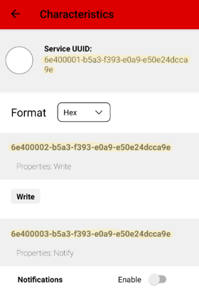
You should have a GATT table similar to the one above.
Remarks
If the GATT table still unchanged, you have to update the GATT Table by disabling-enabling the Bluetooth LE connection. If it still doesn't work properly, reinitialize the GATT information cached by erasing the pairing connection, go to your device settings to dissociate it from the SimpleLink™ CC2340RX LaunchPad™
Customize the project
After this section you will be able to use few features of the device such as using hardware to send data to your phone by different ways.
Handle LEDs
First we need to know how to set up LED.
Open data_stream.syscfg → TI DRIVERS → GPIO.
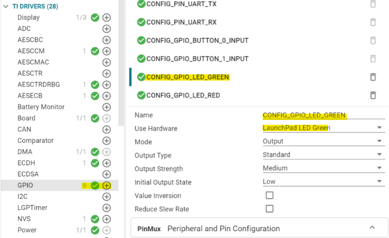
For this example, you should see 6 different GPIOs set up, you can choose the exact software name for each led, here for the green led we
have choose CONFIG_GPIO_LED_GREEN. Then you have to select bunch of parameters, pay attention to attach the right hardware device.
You could find below several functions to interact with this led: CONFIG_GPIO_LED_GREEN.
  GPIO_write(CONFIG_GPIO_LED_GREEN, CONFIG_LED_ON); // turn on the LED
  GPIO_write(CONFIG_GPIO_LED_GREEN, CONFIG_LED_OFF); // turn off the LED
  GPIO_toggle(CONFIG_GPIO_LED_GREEN); // toggle the LED
Handle an LED
Turn on both LED when receiving the expected keyword
Here the goal is to turn on both led when the peripheral received a specific value from the writing characteristic.
To do so, we need to analyze the content of the buffer and compare it to an expected keyword.
Open the app_data_stream.c file, located in app → Profiles in the data_stream project.
Find the DataStream_incomingDataCB( DataStream_dataIn_t *dataIn ) function at the middle of the file.
First, turn off the led at start and disable the toggle when receiving data. To do so, comment the GPIO_write()
functions in the DataStream_start() function in the app_data_stream.c file.
  bStatus_t DataStream_start( void )
  {
    bStatus_t status = SUCCESS;

    status = DSP_start( &ds_profileCB );
    if( status != SUCCESS )
    {
      // Return status value
      return status;
    }
    // Set LEDs
    //GPIO_write( CONFIG_GPIO_LED_RED, CONFIG_LED_OFF );
    //GPIO_write( CONFIG_GPIO_LED_GREEN, CONFIG_LED_ON );
Comment the last two lines
To disable the toggle, comment the GPIO_toggle() functions in the DS_incomingDataCB() function
in the app_data_stream.c file.
  // Clear lines
    MenuModule_clearLines(APP_MENU_PROFILE_STATUS_LINE1, APP_MENU_PROFILE_STATUS_LINE3);

    // Toggle LEDs to indicate that data was received
    //GPIO_toggle( CONFIG_GPIO_LED_RED );
    //GPIO_toggle( CONFIG_GPIO_LED_GREEN );
Comment the last two lines
Add this code just before the change upper case to lower case and lower case to upper case section. This code will turn on both LEDs when the expected word is entered and turn off when is not.
  if(len == (sizeof(keyWord) - 1))
  {
    if(!strncmp((const char*)pValue, (const char*)keyWord, len))
    {
      GPIO_write(CONFIG_GPIO_LED_RED, CONFIG_LED_ON);
      GPIO_write(CONFIG_GPIO_LED_GREEN, CONFIG_LED_ON);
    }
  }else
  {
    GPIO_write(CONFIG_GPIO_LED_RED, CONFIG_LED_OFF);
    GPIO_write(CONFIG_GPIO_LED_GREEN, CONFIG_LED_OFF);
  }
Code to add before the changing case section in the DS_incomingDataCB() function of the app_data_stream.c file
Don't forget to add your expected word at the beginning of the function, here we are waiting for the word "red".
  static void DS_incomingDataCB( uint16 connHandle, char *pValue, uint16 len )
  {
  bStatus_t status = SUCCESS;
  char dataOut[] = "Data size is too long";
  uint16 i = 0;
  uint8_t keyWord[] = "red";//add this line with your word
Initialization of the expected word in the app_data_stream.c file
Test your changes
At this point you can build and flash the code on the device.
Warning
The keyword is case sensitive !
Send Data to the Phone when pressing a button
This section suggests new ways to send data to the central device. For this lab, the left button of the SimpleLink™ CC2340RX LaunchPad™ is used but you could consider using any other peripheral (GPIO, UART, I2C, SPI, etc.). This section goes deeper in the code than the previous ones and takes about 30 minutes.
Enable a task to handle the button
A new FreeRTOS task will be created and the button configured to trigger an interruption.
Merge the empty example into data_stream
First you need to merge the empty example into the data_stream one.
Prepare the environment
Import the
emptyproject example, making sure to select the same RTOS and Toolchain as for thedata_streamproject example. Theemptyproject located at:C:\ti\simplelink_cc23xx_sdk_x_xx_xx_xx\examples\rtos\LP_EM_CC2340R5\drivers\emptyNote
All the code modifications will be done in the
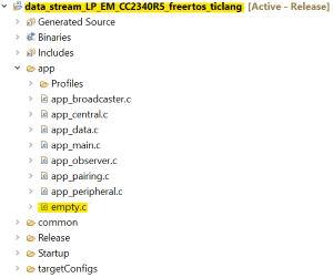
data_streamproject example.Copy the
empty.cfileempty.cis available at the root of theemptyproject example
- Paste the file into the
data_streamproject →app→empty.c
Copy the code used for task creation
- In order to keep the
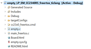
main()function inmain_freertos.cclear, all task creations are deferred to other files. The same will be done for our new task. - In the newly created
empty.c(in thedata_streamproject), add the functionemptyMain. This function can be placed at the end of the file. - Copy-paste into this function the code used in the
emptyproject example to create the task. This code is located in the filemain_freertos.c. Don't forget to add all the includes, variable declarations and other global symbols to your file. Make to ensure the BLEStack is always running with the highest priority. To do so, lower the priority assigned to the newly created function.
   /* POSIX Header files */
   #include <pthread.h>

   /* RTOS header files */
   #include <FreeRTOS.h>
   #include <task.h>

   /* Stack size in bytes */
   #define THREADSTACKSIZE 1024
Header Files and Defines
   void emptyMain(void)
   {
     pthread_t thread;
     pthread_attr_t attrs;
     struct sched_param priParam;
     int retc;

     /* Initialize the attributes structure with default values */
     pthread_attr_init(&attrs);

     /* Set priority, detach state, and stack size attributes */
     priParam.sched_priority = 5; // Lower the priority of this task
     retc = pthread_attr_setschedparam(&attrs, &priParam);
     retc |= pthread_attr_setdetachstate(&attrs, PTHREAD_CREATE_DETACHED);
     retc |= pthread_attr_setstacksize(&attrs, THREADSTACKSIZE);
     if (retc != 0)
     {
       /* failed to set attributes */
       while (1) {}
     }

     retc = pthread_create(&thread, &attrs, mainThread, NULL);
     if (retc != 0)
     {
       /* pthread_create() failed */
       while (1) {}
     }
   }
Code to add in
empty.cfile inside thedata_streamproject. TheemptyMainfunction handles task creation.
- In order to keep the
Call the newly added code from the
main()function inmain_freertos.cmain_freertos.cis available at the root of thedata_streamproject exampleDeclare the
emptyMainfunction as an extern function inmain_freertos.c/******************************************************************************* * EXTERNS */ extern void appMain(void); extern void AssertHandler(uint8 assertCause, uint8 assertSubcause); extern void emptyMain(void); // Add this!The
emptyMainfunction is declared as an extern functionCall the
emptyMainfunction right before turning on the RTOS/* Initialize all applications tasks */ appMain(); emptyMain(); // Add this! /* Start the FreeRTOS scheduler */ vTaskStartScheduler();emptyMain()is called right before turning on the RTOS
Merging done
At this point we have an empty task, now we can use it.
Configure the button
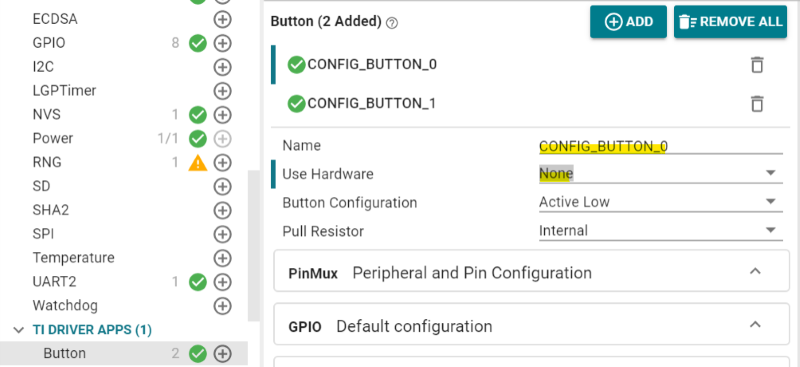
First, disable the hardware attached to CONFIG_BUTTON_0.
Open the .syscfg file of the data_stream project, in TI DRIVER APPS →Button
click on CONFIG_BUTTON_0 and change the value in the Use Hardware field by None.
See the next image for reference.
Note
These previous steps disable the hardware left button for the data_stream menu.
Now, configure a new GPIO for our task. In the same file go to TI Drivers →GPIO
click on the + icon to add a GPIO.
Then configure the new GPIO as shown on the image below.
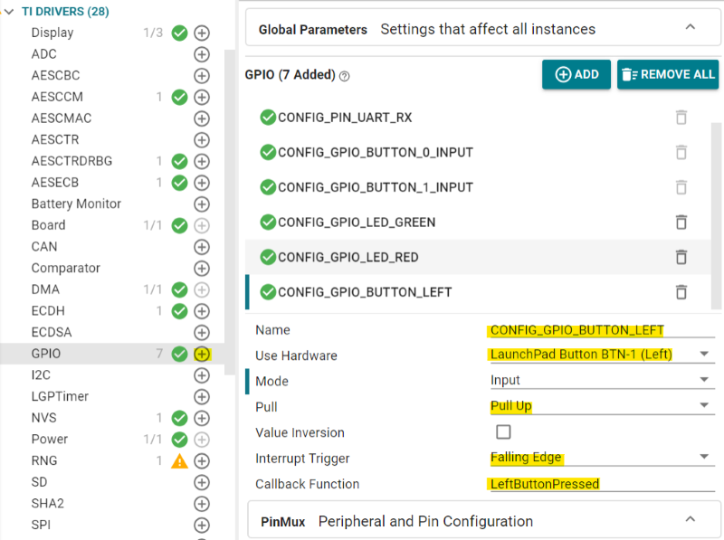
Add the trigger function LeftButtonPressed() at the end of the empty.c file.
  /*********************************************************************
  * @fn      LeftButtonPressed
  *
  * @brief   Send to notify the value only if the left button has been pressed
  *
  * @param   index
  *
  * @return  None.
  */
  void LeftButtonPressed(uint_least8_t index)
  {
    sem_post(&sem);
  }
Add this code at the end of the empty.c file
In the previous code section we have developped the function triggered when the left button is pressed.
In this function you could see the function sem_post() which activate the semaphore when the
button has been pressed.
Open the app_peripheral.c file located in the app folder. In the Peripheral_GAPConnEventHandler() function enables the button
when the BLEAPPUTIL_LINK_ESTABLISHED_EVENT event is caught, see the code below.
  void Peripheral_GAPConnEventHandler(uint32 event, BLEAppUtil_msgHdr_t *pMsgData)
  {
    switch(event)
    {
      case BLEAPPUTIL_LINK_ESTABLISHED_EVENT:
      {
        //Enable the Left Button
        GPIO_enableInt(CONFIG_GPIO_BUTTON_LEFT);//add this line !
code to add in the app_peripheral.c file
Disable it in the same Peripheral_GAPConnEventHandler() function,
but when the BLEAPPUTIL_LINK_TERMINATED_EVENT event is called.
  case BLEAPPUTIL_LINK_TERMINATED_EVENT:
  {
    GPIO_disableInt(CONFIG_GPIO_BUTTON_LEFT); // add this line
    BLEAppUtil_advStart(peripheralAdvHandle_1, &advSetStartParamsSet_1);
    break;
  }
add this code in the app_peripheral.c file, don't forget to add the header #include < ti/drivers/GPIO.h> at the beginning
Implement the thread
Now the most important part is to implement all these elements in the mainThread() function. Pay attention
to place the BLEAppUtil_stackRegister() function at the very beginning of the mainThread, this function
register callback in the ICALL for application events. Also, we create the semaphore, used in the trigger button
function, with sem_init(). Then we call the function sem_wait() in order to wait if the button is triggered.
Once it is thanks to the sem_post() function, the code can proceed and finally send the data with the
DSP_sendData() function.
Find the mainThread code below:
    /*======== mainThread ========*/
    void *mainThread(void *arg0)
    {
      BLEAppUtil_stackRegister();
      int32_t semStatus;
      /* Create semaphore */
      semStatus = sem_init(&sem, 0, 0);
      if (semStatus != 0)
      {
        /* Error creating semaphore */
        while (1) {}
      }
      while (1)
      {
        /* Do not write until read callback executes */
        sem_wait(&sem);
        //Reset the toggle mode when both are ON
        if (GPIO_read(CONFIG_GPIO_LED_RED) == 1 && GPIO_read(CONFIG_GPIO_LED_GREEN) == 1)
        {
          GPIO_toggle( CONFIG_GPIO_LED_GREEN );
        }
        GPIO_toggle( CONFIG_GPIO_LED_RED );
        DSP_sendData(buttonWord,sizeof(buttonWord));
        GPIO_toggle( CONFIG_GPIO_LED_GREEN );
      }
    }
Code of the mainThread() function in the empty.cfile
Make sure to declare all the right headers and differents using functions and variables
before the mainTread function in the empty.cfile.
    /*Bcomdef and semaphore include*/
    #include <semaphore.h>
    #include "bcomdef.h"

    /* External Function */
    extern bStatus_t DSP_sendData( uint8 *pValue, uint16 len );
    extern void BLEAppUtil_stackRegister();

    /* Local Function */
    void LeftButtonPressed(uint_least8_t index);

    /*Local Variable*/
    static sem_t sem;
    uint8 buttonWord[] = "LEFT";
To summarize, this section allows you to send data using the notify characteristic when you are pressing a button on the device.
We're using semaphores when the function LeftButtonPressed() is triggered, it will send a string value to the characteristic with
the DSP_sendData() function. With this example, once the button is pressed the content of buttonWord which contains
the value LEFT is sending and both LEDs, green and red toggle to indicate that the data is received.
Test your changes
At this point you can build and flash the code on the device.
You should have a result similar to the one below, make sure to enable the notify by switching on the notification button. The value in the
notify characteristic should be LEFT without entering anything in the writing characteristic.
Note
Pay attention to select UTF-8 in the combo box, otherwhise the value will be in hexadecimal unit.
Congratulations!
You have completed this lab 🏆
References
SimpleLink™ CC2340RX LaunchPad™
TI SimpleLink Connect on Apple App Store
TI SimpleLink Connect on Google App Store
This work is licensed under a Creative Commons Attribution-NonCommercial-NoDerivatives 4.0 International License.