Note
As of 2021, this document follows the Appropriate Language nomenclature directive from Bluetooth SIG. The SDK project names, APIs and code are not yet ported and use the old nomenclature. For details on how to correlate between the two, please open the PDF document Appropriate Language Mapping Tables.
Introduction
In this module we will learn about Bluetooth® low energy (BLE) connections; How is a BLE connection formed? What information needs to be shared by two devices in order for them to stay connected? How can BLE connections be updated? This tutorial will give you an overview of how to set up BLE connections suited to your needs.
In this lab we will be working with Project Zero and BTool in order to form a BLE connection. In the first two tasks two devices will be programmed, one as a BLE peripheral and one with the Host test project which can be used together with the program BTool. In the third task, BTool will be used to initiate a connection. In the fourth and fifth tasks, the connection parameters will be updated, both from the Peripheral and Central sides. In the last task the connection will be terminated.
This tutorial will take about two hours to complete and requires basic embedded programming skills (see the Prerequisites section for details).
Attention
This lab cannot be run from CCS Cloud. In order to do this lab, you need to have Code Composer Studio (CCS) installed locally. You also need to install the SimpleLink™ Bluetooth® low energy CC2640R2 software development kit (SDK).
Prerequisites
Hardware
For this lab, you need two Bluetooth-enabled development boards.
Other SimpleLink Academy Labs
- Completion of BLE Basics
- Completion of BLE Scanning and Advertising
Software
- CCS 9 installed with support for CC13xx/CC26xx devices.
- SimpleLink™ CC2640R2 SDK 5.30
- BTool (located in the
tools\blestackdirectory of the SimpleLink™ CC2640R2 SDK)
Recommended reading
- Getting Started chapter of the TI BLE-Stack User's Guide
- The CC2640R2 SDK Platform chapter of the TI BLE-Stack User's Guide
- Developing a Custom Application chapter of the TI BLE-Stack User's Guide
About BLE Connections
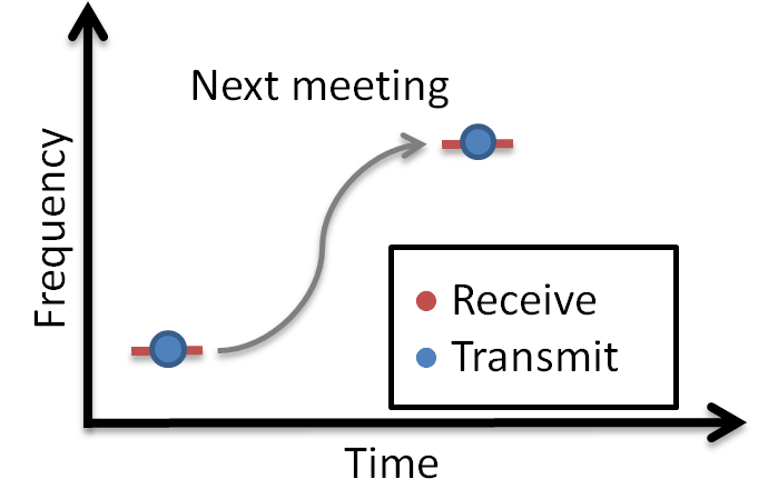
What is a BLE connection? A connection implies a link between devices over time. BLE is a synchronous radio frequency (RF) protocol, meaning that any transmission between devices must be scheduled. A BLE connection can thus be perceived as a series of meetings where two devices transmit and receive information at the same time, on the same radio frequency. In order for this to work, the devices must agree on where (that is, on what frequency) and when next to meet. The BLE-Stack handles connection timing and frequency hopping. The later will not be further explained in the following text. (If you want to know more about frequency hopping, you can read about this in the TI BLE-Stack User's Guide.) The timing, however, we will dive deeper into, in the Connection Parameters section.
A BLE connection always consists of two devices. The device that initiates the connection is called the Central. This device also has the final word on timing and frequency hopping. The other device is called the Peripheral.
The Link Layer
The Link Layer is a part of a Bluetooth Low Energy application that keeps track of whether the device is in a connected state (link) or not. As described in BLE Scanning and Advertising, in order for BLE devices to find each other, they must either scan or advertise. A scanning device that has found a connectable advertiser can initiate a connection. The Link Layer states are summed up in the following figure.
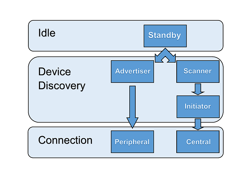
As explained in BLE Scanning and Advertising, a Bluetooth Low Energy device has a defined GAPRole, which can be one or more of the following: Broadcaster, Observer, Peripheral or Central. As only peripherals and centrals can enter connections, these two will be the focus of this lab. A Peripheral is a device with the ability to advertise, and enter a connection allowing to be controlled. A Central is a device that can scan for BLE devices and initiate connections. The Central will always be the controller of the connection.
BLE Connection Life Cycle
As mentioned, the connection must be initiated by the Central and then accepted by the peripheral device. The connection can be terminated from either the Central or the Peripheral.
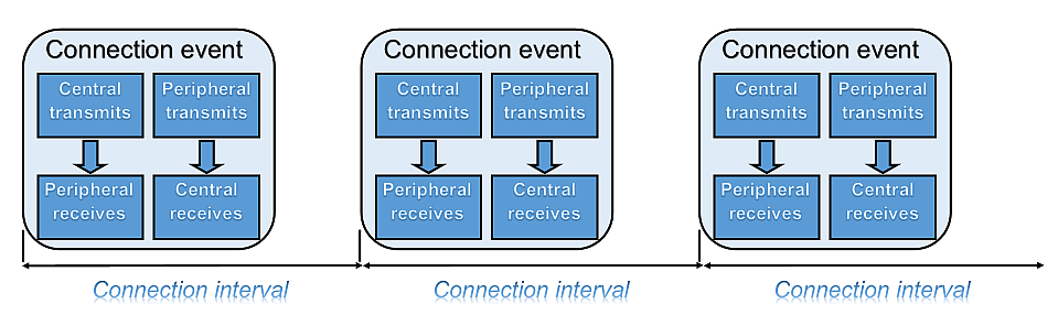
The two BLE devices are connected as long as they periodically exchange data. This exchange is called a connection event and consists of both devices transmitting and receiving info consecutively. Each connection event starts with the Central transmitting and the Peripheral receiving. Then the Peripheral transmits and the Central receives.
Quiz
Which statement is true?
In which file can you find the implemented GAPRole API of Project Zero?
Which of the following is not a GAPRole?
Can the Central and the Peripheral communicate outside of the connection events?
Task 1 – Set up a Peripheral Device
For our Central device to have something to connect to, we need to set up a BLE peripheral device. We will use Project Zero for this purpose. If you have already completed any other BLE SimpleLink Academy BLE modules, you should have a device running Project Zero ready. You can also find Project Zero in CCS in Resource Explorer, or import it directly from the CC2640R2 SDK. If you haven't already done so, you will have to download and import the project before building and debugging the project.
Project Zero uses the peripheral GAPRole. If you want to check that your peripheral device is advertising, you can use your phone. This is explained in the Bluetooth Low Energy Fundamentals SimpleLink Academy module.
Great!
Now we have a peripheral our Central device can connect to. Let's proceed!
Task 2 – Use Host Test with BTool
BTool is a tool bundled with the SimpleLink CC2640R2 SDK, found under
<SDK_INSTALL_DIR>\tools\blestack\btool. Open the Run_BTool.bat file to start
BTool.
In order to use BTool, your computer must be connected to a CC2640R2 LaunchPad running the Host Test example project. In this module we will use BTool to control a BLE Central, but it can be used for other situations as well. This means that not all commands found in BTool are suitable or permitted.
Program a CC2640R2 LaunchPad with Host Test
Attention
To make sure the correct device is flashed with the Host Test project (and that the peripheral device is not overwritten), you should assign a specific LaunchPad to each CCS project. Instructions for this is found here.
Import the Host Test app and stack project to CCS by selecting Project →
Import CCS Projects... The project is located under
<SDK_INSTALL_DIR>\examples\rtos\CC2640R2_LAUNCHXL\blestack\host_test.
- Build
host_test_cc2640r2lp_stack_libraryby right-clicking on it and selecting Build. - Build and load the program by right-clicking on
host_test_cc2640r2lp_appand selecting Debug As → Code Composer Debug Session. - Terminate the Debug session by pressing the red square.
Open BTool
Open Run_BTool.bat in <SDK_INSTALL_DIR>\tools\blestack\btool.
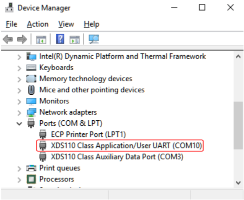
You will be prompted for the COM port of the device. You can find this by opening the Windows Device Manager. (Right click on This PC → More → Properties. Device Manager is found on the menu to the left.) Look for the port called XDS110 Class Application/User UART.
If everything went well, BTool will start printing green and blue events. (If you're seeing yellow or red events, please make sure you found the correct COM port and that the CC2640R2 device is not paused by a debug session in CCS. You may also have to restart the CC2640R2F device before you open the connection with BTool.)
If you scroll all the way to the top of the BTool log, you can see that the device has been initialized as a Central with GAP.
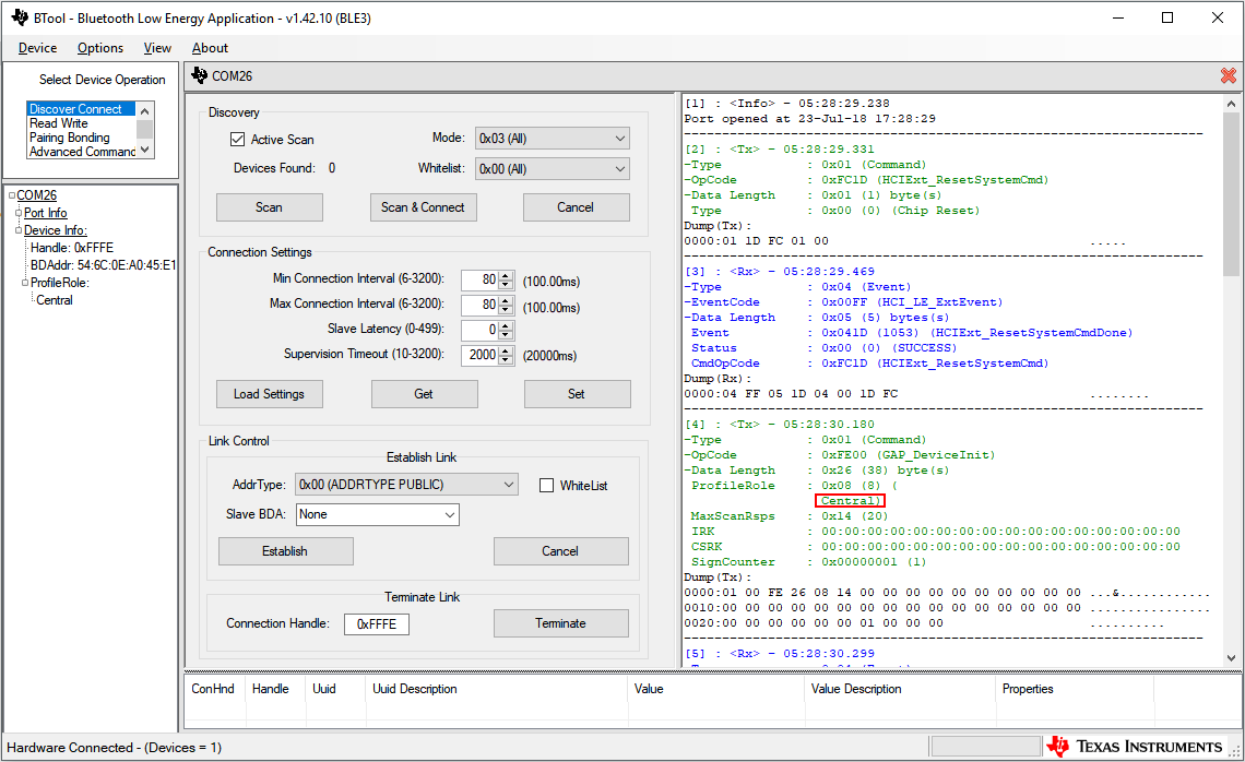
To the left BTool displays information about the host device. This is also where information about any active connections will be displayed. In the center BTool prints out a log of all commands and events. To the right, some actions are displayed.
When the user sends a command, this is printed in green. These command log
entries start with <Tx> as they are transmitted from BTool to the CC2640R2
device running Host Test. Events received from the CC2640R2 running Host Test
are printed in blue and start with <Rx>. For each command sent, BTool
will receive one GAP_HCI_ExtentionCommandStatus event to indicate that the
command was received.
Task 3 – Initiate a Connection
Scan for Nearby Devices
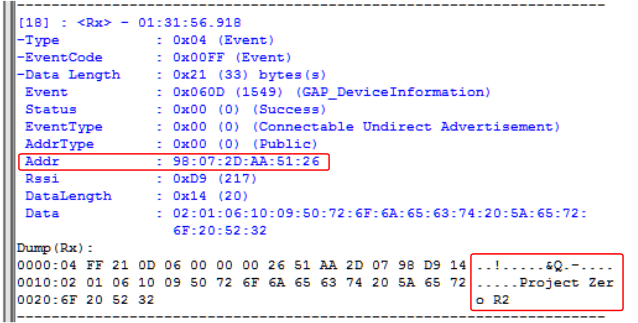
Press the Scan button. BTool will start printing out GAP_DeviceInformation
events. When the scan is finished, a GAP_DeviceDiscoveryDoneevent will give
a summary of the discovered devices. If the scanner found multiple BLE devices,
look through the log for the Project Zero device discovery event in order to
find your peripheral device's address.
Connect to Project Zero
Choose the correct Peripheral BDA (Bluetooth Device Address) and press Establish to connect to the peripheral device.
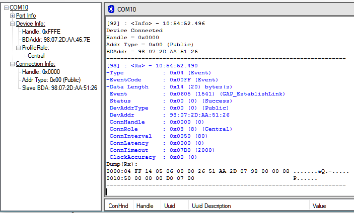
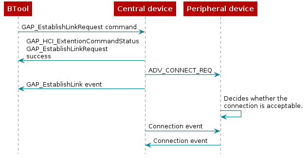
BTool will send a GAP_EstablishLinkRequest command which will prompt the
device to send a connection request through the BLE Stack to Project Zero. If
the connection is successful, a GAP_EstablishLink event will be posted with
information with information about the connection. Connection info will also
appear in the left column.
By using a BLE packet sniffer, we can see what is transmitted over the air. Here is a printout of the connection request packet and the following connection event packets.
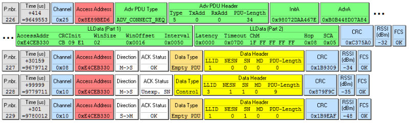
The connection request packet is the BLE packet sent from the Central to initiate a connection with a Peripheral. It contains the addresses of both the Central and the Peripheral in the requested connection (under initA and AdvA). It also contains information about the packet itself; e.g the packet type and how to calculate the CRC (cyclic redundancy check). If you're curious, you can read about some of the fields in the connection request packet, below:
- P.nbr. (226) - Packet sniffer's packet number.
- Time (us) (+414) - Time since last packet received.
- Channel (0x25) - BLE channel this packet was sent on(0x25 = 37). As explained in BLE Scanning and Advertising, channels 37, 38 and 39 are advertising channels while the channel 0-36 are data channels.
- Adv PDU Type (ADV_CONNECT_REQ) - Connection request packet. (PDU = Packet Data Unit)
- PDU-Length (34) -Length of the packet.
- InitA (0x98072DAA67E) - BDA (Bluetooth device address) of the initiator (Central).
- AdvA (0xB0B448D07AB4) - BDA of the intended Peripheral device.
- Interval, Latency and Timeout (0x0050, 0x0000 and 0x07D0) - Connection parameters (see the next section). Here the connection interval is 0x0050 which equals 80 (100 ms), the Peripheral latency is zero and the connection timeout is 0x07D0 = 2000 ms.
- ChM (1F FF FF FF FF) - Channel map. Here the channel map is 1F FF FF FF FF = 0001 1111 1111 1111 1111 1111 1111 1111 1111 1111 in binary, meaning that all data channels (0-37) will be used in this connection. Channel 37-39 will not be used, which is indicated by the zeros in the first three positions.
- Hop (0x08) - Channel hop increment. You can see that the first data packet is sent on channel 0x08, and the next on channel 0x10 (=16).
- SCA (0x05) - Sleep clock accuracy.
- CRC (0xC375A0) - Cyclic redundancy check. CRC is used to check that the full packet has been received.
- RSSI (-32) - Relative signal strength indication.
After having sent the connection request, the Central starts sending connection event packets (yellow). The bottom yellow packet is the Peripheral responding. In addition to the fields common with the connection request packet, the connection event packets contain:
- Time (us) - By looking at the timestamps of the connection event data packets, the connection interval can be determined. (The connection interval will be further discussed in a following section.)
- Access Address (0xE4CEB330) - Random generated address (ID) for this connection.
- Direction (C→P) - Central to Peripheral or Peripheral to Central.
- NESN (1) - Next expected sequence number.
- SN (0) - Sequence number. By comparing the NESN to the SN of the next packet, the BLE stack determines whether a packet has been missed. This is also how the packet sniffer sets the ACK Status.
What Happens on the Peripheral Side?
By default, Project Zero advertises with connectable undirected advertisements.
This is defined by the GAPROLE_ADV_EVENT_TYPE profile parameter in
peripheral.h. (You can read more about advertising modes in BLE Scanning and
Advertising.) When using
connectable undirected advertisements, the peripheral device accepts connection
requests from any initiator. The peripheral does not send a packet to notify
the Central that the connection has been accepted. Instead it waits for the
first connection event.
Connection Parameters
When forming a BLE connection, four parameters must be determined. They all have to do with the connection timing:
- Minimum and maximum connection interval
- Peripheral latency
- Supervision time-out
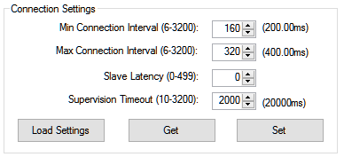
The connection parameters are set in the Central before initiating the connection. GAP handles these parameters. In BTool, you can find the connection settings to the right, under Discover/Connect. Please note that in BTool, these connection settings cannot be used to update the connection parameters in an active connection.
Here we'll focus on the connection interval. If you want to know more about Peripheral latency or supervision time-out you can read about them in the TI BLE-Stack User's Guide in the Developing a Bluetooth Low Energy Application section.
Connection Interval
The connection interval is the time between each connection event. The connection interval must be agreed upon by the two devices in the connection in order for them to be transmitting and receiving at the same time. The connection interval has to be between 7.5 ms and 4 s to comply with the Bluetooth Core Specification. Each connection event consumes power, therefore we generally want a large connection interval. On the other hand, the connection interval represents latency. This means that in a connection with 1 s connection interval, a button press on the Peripheral device might not be registered on the Central device before 1 s has passed.
The connection interval is defined in terms of a minimum and a maximum value. If you want your application to have a fixed connection interval, you can give both variables the same value. Sometimes we want to give the Central device the freedom to change the connection interval without any further input from the user. In that case, give the minimum and maximum variables different values. The Central device will then be free to change its connection interval, as long as it stays within the defined limits. Per default, the device will start with as large connection interval as possible (i.e. the max value will be chosen by the BLE stack as the connection interval). This in order to minimize power consumption.
Quiz
For an application that needs low latency between an event happening and a message being transmitted, which connection interval would you choose?
Consider the following connection settings and decide what the initial connection interval will be:
Which statement(s) are true?
Task 4 – Changing the Connection Interval from BTool
In order to change the connection interval, BTool must first give the new parameters to the Central device. Then the Central must send a connection parameter update request to the Peripheral.
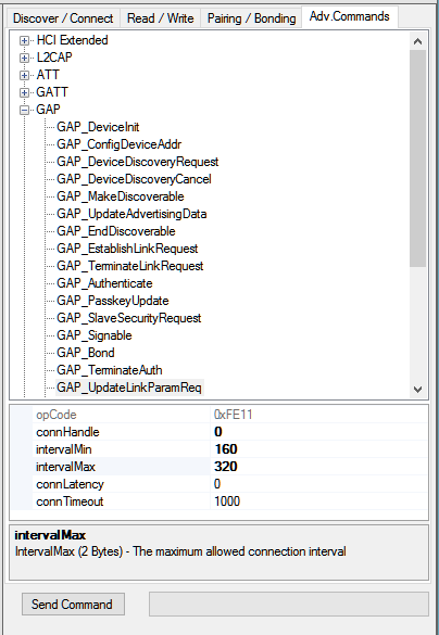
Under Advanced Commands, find GAP_UpdateLinkParamReq. Choose new values for
intervalMin and intervalMax, e.g. 160 and 320. (Remember that these
values are given in 1.25 ms, which means that intervalMax = 320 will give a
connection interval of 400 ms.) Don't forget to press Send Command.
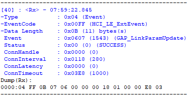
A short while after the GAP_UpdateLinkParamReq command is sent, a
GAP_LinkParamUpdate event is received. This event contains information about
the connection. There is only one value for connection interval
(ConnInterval), because a value between intervalMin and intervalMax has
been chosen.
Task 5 – Connection Parameter Update from the Peripheral
It seems unfair that only the Central device has something to say when it comes to the connection parameters. The Peripheral device can send a connection parameter update request, which will be processed by the Central device. Let's configure Project Zero to enable this functionality!
In this case we want to use the L2CAP layer to conduct the connection parameter
update. Go into the project predefines (Project →
Properties → Build → ARM Compiler → Predefined Symbols) and add
L2CAP_CONN_UPDATE.
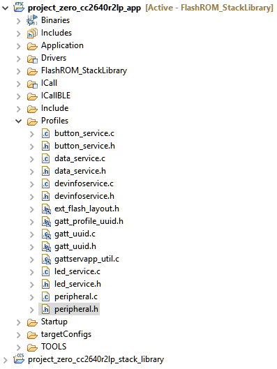
The technicalities of this operation will be taken care of by the GAPRole. As
Project Zero is a peripheral device, we should look in the GAPRole file
peripheral.h, which is found in the PROFILES folder of the app project.
Scroll down until you find the list of CONSTANTS. These are
all the parameters that can be changed using the GAPRole_SetParameter()
function. Choose the one you think will control whether the device sends a
connection parameter update request. (Don't worry if you're not sure which one
to pick, there's a solution further down on this page.)
Now we know what function to use (GAPRole_SetParameter()) and what parameter
to update (hopefully), so we must find out what value to give the parameter.
Again, we should look in peripheral.h. Scrolling a bit further down, you'll
notice a list of defines beginning with
GAPROLE_LINK_PARAM_UPDATE_WAIT_REMOTE_PARAMS. That sound's about right! Again,
choose a value! (And don't worry, a solution will be provided.)
The last thing we need to find out is where to use this function. You will
notice that a section of ProjectZero_init() in project_zero.c is titled
BLE Stack initialization. Here the function GAPRole_SetParameter() is used
multiple times, so it seems like a fitting place. Insert your code here. We must
also give GAPRole the connection parameter values we wish to update to, so
choose some values. If you're not sure what to put, sneak a peak at the solution
below.
// ******************************************************************
// BLE Stack initialization
// ******************************************************************

// Whether to enable automatic parameter update request when a connection is
// formed
uint8_t enableUpdateRequest = GAPROLE_LINK_PARAM_UPDATE_INITIATE_BOTH_PARAMS;

uint16_t desiredMinInterval = 200;
uint16_t desiredMaxInterval = 280;
uint16_t desiredSlaveLatency = 0;
uint16_t desiredConnTimeout = 1000;

GAPRole_SetParameter(GAPROLE_PARAM_UPDATE_ENABLE, sizeof(uint8_t),
                     &enableUpdateRequest);

GAPRole_SetParameter(GAPROLE_MIN_CONN_INTERVAL, sizeof(uint16_t),
                     &desiredMinInterval);
GAPRole_SetParameter(GAPROLE_MAX_CONN_INTERVAL, sizeof(uint16_t),
                     &desiredMaxInterval);
GAPRole_SetParameter(GAPROLE_SLAVE_LATENCY, sizeof(uint16_t),
                     &desiredSlaveLatency);
GAPRole_SetParameter(GAPROLE_TIMEOUT_MULTIPLIER, sizeof(uint16_t),
                     &desiredConnTimeout);
project_zero.c :: ProjectZero_init() – Enable connection parameter update request.
Again, be careful that you're programming the correct device. The parameter
update request will be sent automatically after the connection is formed. GAP
controls how long the Peripheral device has to wait from it enters the connection
until it can send the parameter update request through the
TGAP_CONN_PAUSE_PERIPHERAL define. In the BLE Stack the default value is 6
seconds. The GAP_LinkParamUpdateRequest event should thus show up in BTool
not long after the connection has been formed.
Task 6 – Terminate the Connection
At some point, the connection has done its job and it's time to break the
connection. In BTool, terminating the connection is simply done by pressing
Terminate under Discover/Connect. Please make sure that you have the correct
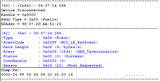
connection handle entered. This should trigger a GAP_TerminateLink event with
the reason 0x16 (which is 22 in decimal), Host requested termination.
Terminate the Connection from the Peripheral
Let's program the Peripheral to disconnect when a button is pressed. We will use
GAPRole_TerminateConnection(). This function, defined in the peripheral
GAPRole, tells GAP to terminate the connection. This gets broadcasted to the
Central, along with a reason why the connection was terminated. Simultaneously,
a GAP_LINK_TERMINATED_EVENT gets posted in the GAPRole event queue. (This
event gets posted whether the termination was intentional or not.)
If we want the termination to happen with a button press, we must find the
function in project_zero.c where button presses are processed. This function
is called user_handleButtonPress(). Choose either BUTTON0 (left button aka
BTN-1) or BUTTON1 (right button) and call the function
GAPRole_TerminateConnection().
case Board_BUTTON0:
      ButtonService_SetParameter(BS_BUTTON0_ID,
                                 sizeof(pState->state),
                                 &pState->state);
      GAPRole_TerminateConnection();
      break;
project_zero.c :: user_handleButtonPress() – Terminating the connection.
Rebuild and debug Project Zero. In BTool, form the connection. Pressing the button on the peripheral device will cause the connection to terminate with the reason 0x13, Peer requested termination.
Further Reading
In this SimpleLink Academy lab, we have talked a lot about what a BLE connection is, but very little about its purpose. Usually, we want to exchange specific information between the two devices. This can be accomplished with Bluetooth Services and Characteristics. If you want to learn about this, you should move on to the SimpleLink Academy module Bluetooth Low Energy Custom Profile.
References
Bluetooth Low Energy Core Specification
This work is licensed under a Creative Commons Attribution-NonCommercial-NoDerivatives 4.0 International License.