Note
As of 2021, this document follows the Appropriate Language nomenclature directive from Bluetooth SIG. The SDK project names, APIs and code are not yet ported and use the old nomenclature. For details on how to correlate between the two, please open the PDF document Appropriate Language Mapping Tables.
Introduction
This module demonstrates how to integrate TI Drivers and the SAIL Plugin code into a BLE project. Adding TI Drivers and SimpleLink Plugin code allows us to take our BLE project to the next level by incorporating external data in our SimpleLink BLE application.
This lab session uses the SimpleLink™ Bluetooth® low energy CC2640R2F wireless MCU LaunchPad™ development kit and, optionally, the BOOSTXL-BASSENSORS BoosterPack™. First, we will give a comparison of using TI-RTOS vs. POSIX threads in a BLE project. Next, the user will be given the option to follow tasks that are designed to use POSIX or TI-RTOS threads. In the POSIX tasks, we will add POSIX and I2CTMP116 based threads by making some small changes to the BLE application. In the alternative tasks, TI Drivers threads are added to a non-POSIX BLE project. In the final two tasks, regardless of which tasks were used above, we will create a new BLE GATT service and send our measurement data over BLE to a Central device.
For the latter tasks, either a Bluetooth low energy enabled cell-phone or an
evaluation kit running the TI host_test sample application is required. The
advantage of using host_test is that the TI tools, such as BTool, can be
used.
The 4 tasks in this lab session are targeted to be completed within a 2 hour time frame. There should be an intermediate level of knowledge of the C programming language as well as experience with embedded software development to be able to complete the tasks.
It is recommended to read the Bluetooth® 4.2 (BLE-Stack) Users Guide alongside this lab for details and further information.
Prerequisites
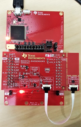
Hardware
For this lab, you need one CC2640R2 Bluetooth-enabled development board and a boosterpack:
Software
- CCS 9 or IAR 8.32.2 installed with support for CC13xx/CC26xx devices.
- SimpleLink™ CC2640R2 SDK 5.30
- SAIL Plugin 1.50.00
For testing, a Bluetooth client application is required:
- BTool (located in the
tools\blestackdirectory of the SimpleLink™ SDK installation) OR - Bluetooth mobile apps:
- Android: BLE Scanner by Bluepixel Technology LLP - available on the Google Play store
- iOS: LightBlue Explorer - Bluetooth Low Energy by Punch Through - available on the App Store
For testing, a Bluetooth client application is required:
- Additional CC2640R2F Launchpad™ to run
host_testOR - Mobile device for testing
Recommended reading
- Getting Started Chapter of the [TI BLE-Stack User's Guide]
- SimpleLink Academy: Bluetooth Low Energy Fundamentals
- SimpleLink Academy: Making a Custom Profile
- SimpleLink Academy: RTOS Concepts
- SimpleLink Academy: POSIX Project Zero
- SimpleLink Academy: TI Drivers Project Zero
POSIX vs No POSIX
Most TI Drivers examples use POSIX to create tasks and interact with the RTOS. The main advantage of using POSIX is that it allows your examples to run on both TI-RTOS and FreeRTOS. By adding POSIX to your BLE application, you can easily add in features with SimpleLink Plugins because many plugin libraries use POSIX functions. However, as of right now, all of TI’s BLE examples run only on TI-RTOS and do not use POSIX. This can be an issue for customers that want to copy and paste their TI Drivers and Plugin examples directly into their BLE projects because the examples initialize threads using POSIX calls. Not using POSIX has its advantages as well. For example, it saves on Flash memory and users do not need to go through the steps of adding POSIX to a project. The next section outlines how to add POSIX to a project and add a SAIL Plugin thread to your BLE project. Afterwards, we will outline how to add TI Drivers to a non-POSIX BLE project. You can decide based on your application which steps to follow.
Quiz
What is a major benefit of adding POSIX to your project?
POSIX
One use-case for when it can be advantageous to add POSIX to your project is combining the Sensor and Actuator plugin with the BLE stack. Since the SAIL library was built using POSIX calls, POSIX needs to be added to your project before using these modules. Additionally, all of the SAIL examples use POSIX. Adding POSIX to your BLE project allows you to directly copy and paste code from these examples into your BLE project. In the following task, we will use a modified version of the i2ctmp116 example.
Note on TI-RTOS and POSIX
Calls to TI-RTOS can co-exist with calls to POSIX. For example, it is fine to have both calls to pthread_create and Task_construct in the same application.
Introduction to the SAIL Plugin
The Sensor and Actuator Interface Layer (SAIL) plugin provides software modules for interfacing sensors, actuators, input devices, and display devices with your SimpleLink project. This plugin provides source code for SAIL modules and example applications that are supported on SimpleLink LaunchPads. The SAIL plugin has been designed to work with the BOOSTXL-BASSENSORS BoosterPack, so adding sensors and actuator modules to your SimpleLink Project couldn't be easier.
Quiz
What software modules are included in the SAIL plugin?
Task 1 – Adding POSIX to a Project and Creating Threads
This task demonstrate how to create a generic posix thread. You can skip to Task 2 which will add a SAIL posix thread implementation.
Add the following lines to
app_ble.cfg(at the end). This file is found under theToolsfolder./* ================ POSIX configuration ================ */ var Settings = xdc.useModule('ti.posix.tirtos.Settings'); if (Program.build.target.$name.match(/iar/)) { /* * For the IAR target, the 'ti.posix.tirtos.Settings' uses the * MultithreadSupport module. By default, the MultithreadSupport module * use the '--threaded_lib' library which provides a separate 'errno' * per thread and makes other rts libraries reentrant. This library has * a larger footprint which can be a problem for some apps, so we * override the default and disable it here. */ var MultithreadSupport = xdc.useModule('ti.sysbios.rts.iar.MultithreadSupport'); MultithreadSupport.enableMultithreadSupport = false; }app_ble.cfg
- Add the following path (Project → Properties → Build →
ARM Compiler → Include Options → Add dir to #include search path):
${COM_TI_SIMPLELINK_CC2640R2_SDK_INSTALL_DIR}/source/ti/posix/ccs
Create a new file, e.g.
myThread.c, under theApplicationfolder. This is where we will create our posix threads.- Add
“#include <pthread.h>”to top of file - Create a function called
void myThread_create(void)where it initializes the threads. This function will be called inmain()beforeBIOS_start(). We will need to callextern void myThread_create(void)inmain.c - Below is an example on how to create a posix thread:
#include <pthread.h>

#define THREADSTACKSIZE    1024

/*
*  ======== myThread ========
*/
void *myThread(void *arg0) {
  /* We will fill this in later */
  return;
}

/*
*  ======== myThread_create ========
*/
void myThread_create(void) {
   pthread_t           thread;
  pthread_attr_t      pAttrs;
  struct sched_param  priParam;
  int                 retc;

  /* Initialize the attributes structure with default values */
  pthread_attr_init(&pAttrs);

  /* Set priority, detach state, and stack size attributes */
  priParam.sched_priority = 1;
  retc = pthread_attr_setschedparam(&pAttrs, &priParam);
  retc |= pthread_attr_setdetachstate(&pAttrs, PTHREAD_CREATE_DETACHED);
  retc |= pthread_attr_setstacksize(&pAttrs, THREADSTACKSIZE);
  if (retc != 0) {
      /* failed to set attributes */
      while (1) {}
  }

  retc = pthread_create(&thread, &pAttrs, myThread, NULL);
  if (retc != 0) {
      /* pthread_create() failed */
      while (1);
  }
}
Important note about threads
To avoid interfering with BLE calls, all non-BLE threads should have a priority of 1.
- Add
Task 2 – Adding POSIX TMP116 Sensor to Simple Peripheral
1. Import the CC2640R2 Simple Peripheral example into your workspace.
2. Create a new file, i2ctmp116.c, in your project's Application
folder.
3. Copy and paste the code in the expandable box below into the new
i2ctmp116.c file.
Note on i2ctmp116 example
The provided i2ctmp116 code removes most of the print statements, prints the temperature value as an integer instead of a float, and optimizes the example to run more efficiently with BLE tasks. Otherwise, it is the same code found in the SAIL Plugin SDK
The necessary functions for creating a POSIX thread, as mentioned in the previous task, are already included.
/*
 * Copyright (c) 2020, Texas Instruments Incorporated
 * All rights reserved.
 *
 * Redistribution and use in source and binary forms, with or without
 * modification, are permitted provided that the following conditions
 * are met:
 *
 * *  Redistributions of source code must retain the above copyright
 *    notice, this list of conditions and the following disclaimer.
 *
 * *  Redistributions in binary form must reproduce the above copyright
 *    notice, this list of conditions and the following disclaimer in the
 *    documentation and/or other materials provided with the distribution.
 *
 * *  Neither the name of Texas Instruments Incorporated nor the names of
 *    its contributors may be used to endorse or promote products derived
 *    from this software without specific prior written permission.
 *
 * THIS SOFTWARE IS PROVIDED BY THE COPYRIGHT HOLDERS AND CONTRIBUTORS "AS IS"
 * AND ANY EXPRESS OR IMPLIED WARRANTIES, INCLUDING, BUT NOT LIMITED TO,
 * THE IMPLIED WARRANTIES OF MERCHANTABILITY AND FITNESS FOR A PARTICULAR
 * PURPOSE ARE DISCLAIMED. IN NO EVENT SHALL THE COPYRIGHT OWNER OR
 * CONTRIBUTORS BE LIABLE FOR ANY DIRECT, INDIRECT, INCIDENTAL, SPECIAL,
 * EXEMPLARY, OR CONSEQUENTIAL DAMAGES (INCLUDING, BUT NOT LIMITED TO,
 * PROCUREMENT OF SUBSTITUTE GOODS OR SERVICES; LOSS OF USE, DATA, OR PROFITS;
 * OR BUSINESS INTERRUPTION) HOWEVER CAUSED AND ON ANY THEORY OF LIABILITY,
 * WHETHER IN CONTRACT, STRICT LIABILITY, OR TORT (INCLUDING NEGLIGENCE OR
 * OTHERWISE) ARISING IN ANY WAY OUT OF THE USE OF THIS SOFTWARE,
 * EVEN IF ADVISED OF THE POSSIBILITY OF SUCH DAMAGE.
 */

/*
 *    ======== i2ctmp116.c ========
 */
#include <stdint.h>
#include <stddef.h>
#include <unistd.h>

/* POSIX Header files */
#include <pthread.h>
#include <semaphore.h>

/* Driver Header files */
#include <ti/drivers/GPIO.h>
#include <ti/drivers/I2C.h>
#include <ti/display/Display.h>

/* Module Header */
#include <ti/sail/tmp116/tmp116.h>

/* Example/Board Header files */
#include "Board.h"

#define THREADSTACKSIZE    1024

extern Display_Handle dispHandle;

#define SAMPLE_TIME     10        /*In seconds*/
#define HIGH_LIMIT      30.0F
#define LOW_LIMIT       20.0F

#define TMP_TASK_STACK_SIZE   768

TMP116_Handle  tmp116Handle = NULL;
I2C_Handle     i2cHandle    = NULL;

sem_t tmp116Sem;


/* Global values which may be accessed from GUI Composer App */
float temp;

/* Global sample rate which may be accessed and set from GUI Composer App */
volatile uint16_t sampleTime;

/*
 *  ======== tmp116Callback ========
 *  When an ALERTing condition is met on the TMP116 hardware, the ALERT pin
 *  is asserted generating an interrupt. This callback function serves as
 *  an ISR for a single TMP116 sensor.
 */
void tmp116Callback(uint_least8_t index)
{
    sem_post(&tmp116Sem);
}

/*
 *  ======== tmp116AlertTask ========
 *  This task is unblocked when the ALERT pin is asserted and generates an
 *  interrupt. When the TMP116 is in INTERRUPT mode, the status register must
 *  be read to clear the ALERT pin.
 */
void *tmp116AlertTask(void *arg0)
{
    uint16_t data;

    while(1) {

        /* Pend on semaphore, tmp116Sem */
        if (0 == sem_wait(&tmp116Sem)) {

            /* Reads status register, resetting the ALERT pin */
            TMP116_readStatus(tmp116Handle, &data);

            /* Check Object Temperature High Flag */
            if (data & TMP116_STAT_ALR_HI) {
                Display_print0(dispHandle, 6, 0, "ALERT: Object Temperature High\n");
            }

            /* Check Object Temperature Low Flag */
            if (data & TMP116_STAT_ALR_LO) {
                Display_print0(dispHandle, 6, 0, "ALERT: Object Temperature Low\n");
            }

        }
    }
}

/*
 *  ======== sailThread ========
 */
void *sailThread(void *arg0)
{
    I2C_Handle      i2cHandle;
    I2C_Params      i2cParams;
    int             retc;
    pthread_t alertTask;
    pthread_attr_t       pAttrs;
    float hiLim = HIGH_LIMIT;
    float loLim = LOW_LIMIT;
    sampleTime = SAMPLE_TIME;
    struct sched_param  priParam;

    TMP116_Params  tmp116Params;

    /* Call driver init functions */
    GPIO_init();
    I2C_init();
    TMP116_init();

    /* Turn on user LED and TMP116 Sensor */
    GPIO_write(Board_GPIO_LED0, Board_GPIO_LED_ON);
    GPIO_write(Board_TMP116_PWR, Board_TMP116_ON);

    /* Create I2C for usage */
    I2C_Params_init(&i2cParams);

    i2cParams.bitRate = I2C_400kHz;

    i2cHandle = I2C_open(Board_I2C_TMP, &i2cParams);
    if (i2cHandle == NULL) {
        Display_print0(dispHandle, 6, 0, "Error Initializing I2C\n");
        while (1);
    }

    if(0 != sem_init(&tmp116Sem,0,0))
    {
        /* sem_init() failed */
        Display_print0(dispHandle, 6, 0, "tmp116Sem Semaphore creation failed\n");
        while (1);
    }

    pthread_attr_init(&pAttrs);

    priParam.sched_priority = 1;
    pthread_attr_setschedparam(&pAttrs, &priParam);

    pthread_attr_setstacksize(&pAttrs, TMP_TASK_STACK_SIZE);
    retc = pthread_create(&alertTask, &pAttrs, tmp116AlertTask, NULL);
    if (retc != 0) {
        /* pthread_create() failed */
        Display_print0(dispHandle, 6, 0, "Alert Task creation failed\n");
        while (1);
    }

    /* Initialize tmp116Params structure to defaults */
    TMP116_Params_init(&tmp116Params);

    /* Callback for ALERT event */
    tmp116Params.callback = &tmp116Callback;

    /* Open TMP116 sensor with custom Params */
    tmp116Handle = TMP116_open(Board_TMP116, i2cHandle, &tmp116Params);

    /* Check if the open is successful */
    if (tmp116Handle == NULL) {
        Display_print0(dispHandle, 6, 0, "TMP116_ROOMTEMP0 Open Failed!\n");
        while(1);
    }

    /* Allow the sensor hardware to complete its first conversion */
    sleep(2);

    /* Set Object Temperature Alert Limits */
    if (!TMP116_setTempLimit(tmp116Handle, TMP116_CELSIUS, hiLim, loLim)) {
        Display_print0(dispHandle, 6, 0, "Setting Object Temperature Limits Failed!\n");
    }

    /* Get Die Temperature in Celsius */
    if (!TMP116_getTemp(tmp116Handle, TMP116_CELSIUS, &temp)) {
        Display_print0(dispHandle, 6, 0, "TMP116 sensor read failed");
    }

    Display_print1(dispHandle, 6, 0, "Temperature: %d (C)\n", (int32_t) temp);

    /* Begin infinite task loop */
    while (1) {

        /* Get Die and Object Temperatures */
        if (!TMP116_getTemp(tmp116Handle, TMP116_CELSIUS, &temp)) {
            Display_print0(dispHandle, 6, 0, "TMP116 sensor read failed\n");

        }

        Display_print1(dispHandle, 6, 0, "Temp: %d (C)\n\n", (int32_t) temp);

        sleep(sampleTime);
    }
}

void sailThread_create(void) {
     pthread_t           thread;
    pthread_attr_t      pAttrs;
    struct sched_param  priParam;
    int                 retc;

    /* Call driver init functions */
    Board_initGeneral();

    /* Initialize the attributes structure with default values */
    pthread_attr_init(&pAttrs);

    /* Set priority, detach state, and stack size attributes */
    priParam.sched_priority = 1;
    retc = pthread_attr_setschedparam(&pAttrs, &priParam);
    retc |= pthread_attr_setdetachstate(&pAttrs, PTHREAD_CREATE_DETACHED);
    retc |= pthread_attr_setstacksize(&pAttrs, THREADSTACKSIZE);
    if (retc != 0) {
        /* failed to set attributes */
        while (1) {}
    }

    retc = pthread_create(&thread, &pAttrs, sailThread, NULL);
    if (retc != 0) {
        /* pthread_create() failed */
        while (1);
    }
}
i2ctmp116.c
4. Add extern void sailThread_create(void); to the top of main.c under
the Startup folder. Call sailThread_create() in main() as shown below.
      SimplePeripheral_createTask();

      /* Call function to initialize temperature threads */
      sailThread_create();

      /* enable interrupts and start SYS/BIOS */
      BIOS_start();
5. Follow the instructions from Task 1 on adding POSIX to your project. The given code already creates the necessary functions and threads for you (Don't add the myThread from Task 1).
6. Go to Project → Properties → Resource → Linked Resources
→ Path Variables and add SAIL_PLUGIN_INSTALL_DIR with the actual
install path for the SAIL plugin on your computer (e.g. C:\ti\sail_1_50_00_00).
7 Project → Properties → Build → ARM Compiler →
Predefined Symbols and add the following: BOOSTXL_BASSENSORS.
8. Add the following path (Project → Properties → Build → ARM Compiler → Include Options → Add dir to #include search path):
${SAIL_PLUGIN_INSTALL_DIR}/source
9. Go to Project → Properties → Build → ARM Linker → File Search Path, add the following library. Click Close.
${SAIL_PLUGIN_INSTALL_DIR}/source/ti/sail/lib/ccs/cc26x0/sail.lib
10. Copy the following files from
{CC2640R2_SDK_INSTALL_DIR}/source/ti/blestack/boards/CC2640R2_LAUNCHXL/
into the Startup folder of your project. Exclude board.c in Startup from
the project.
CC2640R2_LAUNCHXL.cCC2640R2_LAUNCHXL.hCC2640R2_LAUNCHXL_fxns.cBoard.h
11. Modify the CC2640R2 board files by copy and pasting the code below:
a. CC2640R2_LAUNCHXL.c
- Replace
gpioPinConfigs[]with the following version:#ifdef BOOSTXL_BASSENSORS #define OPT3001_INT_PIN GPIOCC26XX_DIO_27 #else // BOOSTXL_SENSORS #define OPT3001_INT_PIN GPIOCC26XX_DIO_15 #endif GPIO_PinConfig gpioPinConfigs[] = { /* Input pins */ #ifndef BOOSTXL_ULN2003 /* To avoid conflict with board button */ #ifndef BOOSTXL_ADS7142 GPIOCC26XX_DIO_13 | GPIO_CFG_IN_PU | GPIO_CFG_IN_INT_FALLING, /* Button 0 */ #endif GPIOCC26XX_DIO_14 | GPIO_CFG_IN_PU | GPIO_CFG_IN_INT_FALLING, /* Button 1 */ #endif /* CC2640R2_LAUNCHXL_TMP116_INT Pin */ GPIOCC26XX_DIO_25 | GPIO_CFG_IN_PU | GPIO_CFG_IN_INT_FALLING, /* CC2640R2_LAUNCHXL_HDC2010_INT Pin */ GPIOCC26XX_DIO_25 | GPIO_CFG_IN_PU | GPIO_CFG_IN_INT_FALLING, #ifndef BOOSTXL_ULN2003 /* To avoid conflict with OPT3001 Sensor */ /* CC2640R2_LAUNCHXL_OPT3001_INT Pin */ OPT3001_INT_PIN | GPIO_CFG_IN_PU | GPIO_CFG_IN_INT_FALLING, #endif /* CC2640R2_LAUNCHXL_SENSORBP_INT1 interrupt BMI160 */ GPIOCC26XX_DIO_22 | GPIO_CFG_IN_PD | GPIO_CFG_IN_INT_RISING, #ifdef BOOSTXL_ADS7142 GPIOCC26XX_DIO_13 | GPIO_CFG_IN_PU | GPIO_CFG_IN_INT_FALLING, GPIOCC26XX_DIO_17 | GPIO_CFG_IN_PU | GPIO_CFG_IN_INT_FALLING, #endif /* Output pins */ GPIOCC26XX_DIO_07 | GPIO_CFG_OUT_STD | GPIO_CFG_OUT_STR_HIGH | GPIO_CFG_OUT_LOW, /* Green LED */ GPIOCC26XX_DIO_06 | GPIO_CFG_OUT_STD | GPIO_CFG_OUT_STR_HIGH | GPIO_CFG_OUT_LOW, /* Red LED */ /* CC2640R2_LAUNCHXL_TMP116_PWR */ GPIOCC26XX_DIO_30 | GPIO_CFG_OUT_STD | GPIO_CFG_OUT_STR_HIGH | GPIO_CFG_OUT_HIGH, /* CC2640R2_LAUNCHXL_HDC2010_PWR */ GPIOCC26XX_DIO_24 | GPIO_CFG_OUT_STD | GPIO_CFG_OUT_STR_HIGH | GPIO_CFG_OUT_LOW, /* CC2640R2_LAUNCHXL_OPT3001_PWR */ GPIOCC26XX_DIO_29 | GPIO_CFG_OUT_STD | GPIO_CFG_OUT_STR_HIGH | GPIO_CFG_OUT_HIGH, /* CC2640R2_LAUNCHXL_DRV5055_PWR */ GPIOCC26XX_DIO_26 | GPIO_CFG_OUT_STD | GPIO_CFG_OUT_STR_HIGH | GPIO_CFG_OUT_LOW, /* SPI Flash CSN */ GPIOCC26XX_DIO_20 | GPIO_CFG_OUT_STD | GPIO_CFG_OUT_STR_HIGH | GPIO_CFG_OUT_HIGH, GPIOCC26XX_DIO_22 | GPIO_DO_NOT_CONFIG, /* LCD power control */ GPIOCC26XX_DIO_23 | GPIO_DO_NOT_CONFIG /*LCD enable */ };CC2640R2_LAUNCHXL.c :: gpioPinConfigs[]
Change
gpioCallbackFunctions[]to the following:GPIO_CallbackFxn gpioCallbackFunctions[] = { #ifndef BOOSTXL_ULN2003 /* To avoid conflict with board button */ NULL, /* Button 0 */ NULL, /* Button 1 */ #endif NULL, /* TMP116 */ NULL, /* HDC2010 */ #ifndef BOOSTXL_ULN2003 /* To avoid conflict with OPT3001 Sensor */ NULL, /* OPT3001 */ #endif NULL, /* SENSORBP_INT1 */ NULL, /* Callback function for ADS7142 */ NULL, };CC2640R2_LAUNCHXL.c :: gpioCallbackFunctions[]
Remove or comment out the sections for I2S and SD hardware configuration.
  ///*
  // *  =============================== I2S ===============================
  //*/
  //#include <ti/drivers/I2S.h>
  //#include <ti/drivers/i2s/I2SCC26XX.h>
  //
  //I2SCC26XX_Object i2sCC26XXObjects[CC2640R2_LAUNCHXL_I2SCOUNT];
  //
  //const I2SCC26XX_HWAttrs i2sCC26XXHWAttrs[CC2640R2_LAUNCHXL_I2SCOUNT] = {
  //    {
  //        .pinSD1      =  CC2640R2_LAUNCHXL_I2S_ADI,
  //        .pinSD0      =  CC2640R2_LAUNCHXL_I2S_ADO,
  //        .pinSCK      =  CC2640R2_LAUNCHXL_I2S_BCLK,
  //        .pinMCLK     =  CC2640R2_LAUNCHXL_I2S_MCLK,
  //        .pinWS       =  CC2640R2_LAUNCHXL_I2S_WCLK,
  //        .intPriority = ~0,
  //    }
  //};
  //
  //const I2S_Config I2S_config[CC2640R2_LAUNCHXL_I2SCOUNT] = {
  //    {
  //        .object      = &i2sCC26XXObjects[CC2640R2_LAUNCHXL_I2S0],
  //        .hwAttrs     = &i2sCC26XXHWAttrs[CC2640R2_LAUNCHXL_I2S0]
  //    },
  //};
  //
  //const uint_least8_t I2S_count = CC2640R2_LAUNCHXL_I2SCOUNT;
CC2640R2_LAUNCHXL.c :: I2S
  ///*
  // *  =============================== SD ===============================
  // */
  //#include <ti/drivers/SD.h>
  //#include <ti/drivers/sd/SDSPI.h>
  //
  //SDSPI_Object sdspiObjects[CC2640R2_LAUNCHXL_SDCOUNT];
  //
  //const SDSPI_HWAttrs sdspiHWAttrs[CC2640R2_LAUNCHXL_SDCOUNT] = {
  //    {
  //        .spiIndex = CC2640R2_LAUNCHXL_SPI0,
  //        .spiCsGpioIndex = CC2640R2_LAUNCHXL_SDSPI_CS
  //    }
  //};
  //
  //const SD_Config SD_config[CC2640R2_LAUNCHXL_SDCOUNT] = {
  //    {
  //        .fxnTablePtr = &SDSPI_fxnTable,
  //        .object = &sdspiObjects[CC2640R2_LAUNCHXL_SDSPI0],
  //        .hwAttrs = &sdspiHWAttrs[CC2640R2_LAUNCHXL_SDSPI0]
  //    },
  //};
  //
  //const uint_least8_t SD_count = CC2640R2_LAUNCHXL_SDCOUNT;
CC2640R2_LAUNCHXL.c :: SD
Add this code to the end of the file
/*
*  =============================== TMP116 ===============================
*/
#include <ti/sail/tmp116/tmp116.h>

TMP116_Object TMP116_object[CC2640R2_LAUNCHXL_TMP116COUNT];

const TMP116_HWAttrs TMP116_hwAttrs[CC2640R2_LAUNCHXL_TMP116COUNT] = {
      {
          .slaveAddress = TMP116_SA1,
          .gpioIndex = CC2640R2_LAUNCHXL_TMP116_INT,
      },
};

const TMP116_Config TMP116_config[] = {
  {
      .hwAttrs = &TMP116_hwAttrs[0],
      .object =  &TMP116_object[0],
  },
  {NULL, NULL},
};
CC2640R2_LAUNCHXL.c
b. CC2640R2_LAUNCHXL.h
Change the
CC2640R2_LAUNCHXL_GPIONameenum as follows:typedef enum CC2640R2_LAUNCHXL_GPIOName { #ifndef BOOSTXL_ULN2003 /* To avoid conflict with board button */ CC2640R2_LAUNCHXL_GPIO_S1 = 0, CC2640R2_LAUNCHXL_GPIO_S2, #endif CC2640R2_LAUNCHXL_TMP116_INT, CC2640R2_LAUNCHXL_HDC2010_INT, #ifndef BOOSTXL_ULN2003 /* To avoid conflict with OPT3001 Sensor */ CC2640R2_LAUNCHXL_OPT3001_INT, #endif CC2640R2_LAUNCHXL_SENSORBP_INT1, CC2640R2_LAUNCHXL_GPIO_LED_GREEN, CC2640R2_LAUNCHXL_GPIO_LED_RED, CC2640R2_LAUNCHXL_TMP116_PWR, CC2640R2_LAUNCHXL_HDC2010_PWR, CC2640R2_LAUNCHXL_OPT3001_PWR, CC2640R2_LAUNCHXL_DRV5055_PWR, CC2640R2_LAUNCHXL_GPIO_SPI_FLASH_CS, CC2640R2_LAUNCHXL_GPIO_LCD_CS, CC2640R2_LAUNCHXL_GPIO_LCD_POWER, CC2640R2_LAUNCHXL_GPIO_LCD_ENABLE, CC2640R2_LAUNCHXL_GPIOCOUNT } CC2640R2_LAUNCHXL_GPIOName;CC2640R2_LAUNCHXL.h :: CC2640R2_LAUNCHXL_GPIOName enum
Add to the bottom of the file, before the final
#ifdef __cplusplus/*! * @def CC2640R2_LAUNCHXL_TMP116Name * @brief Enum of TMP116 names connected to a CC2640R2_LAUNCHXL dev board */ typedef enum CC2640R2_LAUNCHXL_TMP116Name { CC2640R2_LAUNCHXL_TMP116_0 = 0, CC2640R2_LAUNCHXL_TMP116COUNT } CC2640R2_LAUNCHXL_TMP116Name;CC2640R2_LAUNCHXL.h
c. Board.h
The I2C defines should be as follow (replacing
Board_I2C0andBoard_I2C_TMPdefines):#define Board_I2C0 CC2640R2_LAUNCHXL_I2C0 #define Board_I2C_ADS7142 CC2640R2_LAUNCHXL_I2C0 #define Board_I2C_TMP CC2640R2_LAUNCHXL_I2C0 #define Board_I2C_OPT CC2640R2_LAUNCHXL_I2C0Board.h I2C defines.
Add the TMP116 sensor address
/* Board specific I2C addresses */
#define Board_TMP_ADDR          (0x40)
#define Board_SENSORS_BP_TMP_ADDR Board_TMP_ADDR
Board.h TMP116 sensor address
Copy and paste this with the other
#definesin the file/* TMP116 Sensor */ #define Board_TMP116 CC2640R2_LAUNCHXL_TMP116_0 #define Board_TMP116_ON (1) #define Board_TMP116_PWR CC2640R2_LAUNCHXL_TMP116_PWR #define Board_TMP116COUNT CC2640R2_LAUNCHXL_TMP116COUNTBoard.h
12. Mount the BOOSTXL-BASSENSORS Booster pack on the CC2640R2 LaunchPad as shown in the Hardware section.
13. Build & Debug the new Simple Peripheral project
Open PuTTY (or similar) serial connection with following settings:
- Speed (baud) = 115200
- Data Bits = 8
- Stop Bits = 1
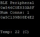
Run your example and observe the output
Along with the usual BLE Simple Peripheral output, your terminal window should display the temperature readings in the image below.
No POSIX
When using TI Drivers in your CC2640R2 application, it is not necessary to add POSIX to your project. This can be advantageous for BLE projects that use a large amount of FLASH memory. In the following tasks, we will use example code that takes an ADC measurement when Button0 is pressed.
Note on ADC + GPIO example
The provided code was designed specifically for this demo.
TI Drivers
Before proceeding to the following tasks, it is recommended to review TI Drivers Project Zero
Task 3 – Creating non-POSIX TI-RTOS Threads
This task show how to implement a generic TI-RTOS thread (task). You can skip to Task 4 for a TI-RTOS task with SAIL implementations.
Create a new file, i.e. myThread.c, where we create our TI-RTOS threads.
- Add
#include <ti/sysbios/knl/Task.h>to the top of the file - Create a function called
Task_FuncPtr myThread_create(void)where it initializes the threads. This function will be called inmain()beforeBIOS_start(). We will need to callextern Task_FuncPtr myThread_create(void)inmain.c. Below is an example on how to create a non-POSIX thread:
#include <xdc/std.h>
#include <xdc/runtime/Error.h>
#include <ti/sysbios/knl/Task.h>

#define THREADSTACKSIZE    1024
Task_Struct myTask;
uint8_t myTaskStack[THREADSTACKSIZE];

Task_FuncPtr *myThread(void *arg0) {
  /* We will fill this in later */
}

Task_FuncPtr myThread_create(void) {
  Task_Params taskParams;

  /* Configure task */
  Task_Params_init(&taskParams);
  taskParams.stack = myTaskStack;
  taskParams.stackSize = THREADSTACKSIZE;
  taskParams.priority = 1;

  Task_construct(&myTask, myThread, &taskParams, Error_IGNORE);
}
Important note about threads
To avoid interfering with BLE calls, all non-BLE threads should have a priority of 1
- Add
More on TI-RTOS
For more information on TI-RTOS tasks, go to the Tasks section under "TI-RTOS (RTOS Kernel) Overview" of the SimpleLink CC2640R2 BLE-Stack User's Guide found in the CC2640R2 SDK
Task 4 – Adding non-POSIX ADC Measurements to Simple Peripheral
1. Import the CC2640R2 SimplePeripheral example into your workspace
2. Create a new file, myThread.c in your project's Application folder
3. Copy and paste the code in the expandable boxes below into the new myThread.c file
Important note about the following code
This code already includes the necessary function for creating a non-POSIX thread, as mentioned in the previous task
#include <stdint.h>
#include <stddef.h>
#include <xdc/std.h>
#include <xdc/runtime/Error.h>
#include <ti/sysbios/BIOS.h>
#include <ti/sysbios/knl/Semaphore.h>
#include <ti/sysbios/knl/Task.h>
/* Driver Header files */
#include <ti/drivers/GPIO.h>
#include <ti/display/Display.h>
#include <ti/drivers/ADC.h>
/* Example/Board Header files */
#include "Board.h"
Task_Struct myTask;
#define THREADSTACKSIZE 1024
uint8_t myTaskStack[THREADSTACKSIZE];
uint16_t adcValue;
extern Display_Handle dispHandle;
Semaphore_Handle adcSem;
/********** gpioButtonFxn0 **********/
void gpioButtonFxn0(uint_least8_t index)
{
/* Clear the GPIO interrupt and toggle an LED */
GPIO_toggle(Board_GPIO_LED0);
Semaphore_post(adcSem);
}
/********** myThread **********/
Task_FuncPtr *myThread(void *arg0) {
ADC_Handle adc;
ADC_Params params;
Semaphore_Params semParams;
Semaphore_Params_init(&semParams);
adcSem = Semaphore_create(0, &semParams, Error_IGNORE);
if(adcSem == NULL)
{
/* Semaphore_create() failed */
Display_print0(dispHandle, 0, 0, "adcSem Semaphore creation failed\n");
while (1);
}
/* Initialize ADC and GPIO drivers */
GPIO_init();
ADC_init();
GPIO_setConfig(Board_GPIO_BUTTON0, GPIO_CFG_IN_PU | GPIO_CFG_IN_INT_FALLING);
/* install Button callback */
GPIO_setCallback(Board_GPIO_BUTTON0, gpioButtonFxn0);
/* Enable interrupts */
GPIO_enableInt(Board_GPIO_BUTTON0);
ADC_Params_init(¶ms);
adc = ADC_open(Board_ADC0, ¶ms);
if (adc == NULL) {
Display_printf(dispHandle, 6, 0, "Error initializing ADC channel 0\n");
while (1);
}
while (1) {
/* Pend on semaphore, tmp116Sem */
Semaphore_pend(adcSem, BIOS_WAIT_FOREVER);
/* Blocking mode conversion */
ADC_convert(adc, &adcValue);
Display_printf(dispHandle, 6, 0, "ADC value: %d\n", adcValue);
}
}
/********** myThread_create **********/
void myThread_create(void) {
Task_Params taskParams;
// Configure task
Task_Params_init(&taskParams);
taskParams.stack = myTaskStack;
taskParams.stackSize = THREADSTACKSIZE;
taskParams.priority = 1;
Task_construct(&myTask, myThread, &taskParams, Error_IGNORE);
}
4. Add extern void myThread_create(void); to the top of main.c in the Startup folder. Call myThread_create() in main().
      SimplePeripheral_createTask();

      /* Call function to initialize temperature threads */
      myThread_create();

      /* enable interrupts and start SYS/BIOS */
      BIOS_start();
5. Build & Debug the new Simple Peripheral project
Open PuTTY (or similar) serial connection with the following settings:
- Speed (baud) = 115200
- Data Bits = 8
- Stop Bits = 1
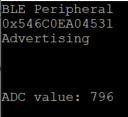
Run your example and observe the output
Press Button 0 on your LaunchPad to take an ADC measurement
Along with the usual BLE Simple Peripheral output, your terminal window should display the ADC readings in the image below.
Task 5 – Add New Service to Simple Peripheral
In order to send our measurement data over BLE, we will need to add a new service and characteristic to hold the data values that are received by either the TMP116 or ADC.
1. Create a new service by using the Example service generator located in the Making a Custom Profile lab. The new service should be filled out as shown below:
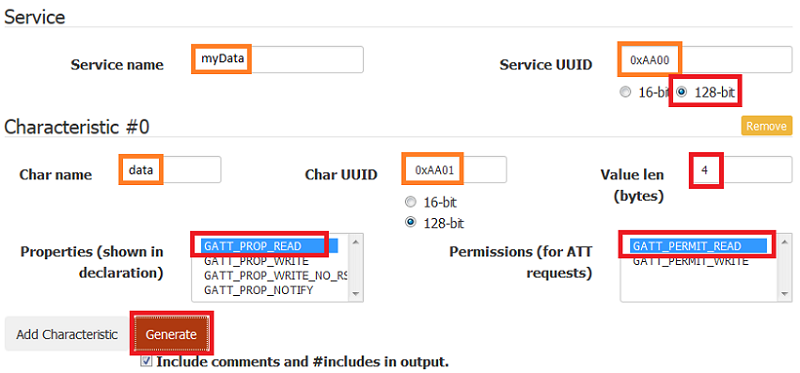
Note for ADC samples
Since the CC2640R2 uses a 12 bit ADC, the characteristic length can be shortened to 2 bytes.
2. Add a new source and header file to your project's PROFILES folder.
Give the files the same name as the files generated by the Service Generator.
In this example, it is myData.h and myData.c.
3. Use the yellow Select text button to select the content of the generated
header and implementation file for your new service. Copy-paste the content into
their respective CCS source and header files. You might have to include bcomdef.h
in the header file myData.h.
#include <bcomdef.h>
myData.h - Include bcomdef.h
4. Add the lines shown below to
simple_peripheral.c as directed in application-snippets.c
#include "devinfoservice.h"
#include "simple_gatt_profile.h"
#include "ll_common.h"
#include "myData.h"
simple_peripheral.c - Include new header file
Add the following lines of code to SimplePeripheral_init().
// Initialize GATT attributes
GGS_AddService(GATT_ALL_SERVICES);           // GAP GATT Service
GATTServApp_AddService(GATT_ALL_SERVICES);   // GATT Service
DevInfo_AddService();                        // Device Information Service
SimpleProfile_AddService(GATT_ALL_SERVICES); // Simple GATT Profile
MyData_AddService( selfEntity );
simple_peripheral.c - Add new service
5. Build and flash the Simple Peripheral app project.
Now, reconnect to your Simple Peripheral and you should see your new service. What happens if you read the data characteristic?
If you do not see the new service, you may have to toggle the Bluetooth on your mobile device to clear the smartphone Bluetooth cache.
Task 6 – Sending Measurement Data over BLE
1. Create a global variable for storing measurement data in the file with your new tasks. For example, uint32_t myData. Add extern uint32_t myData to the top of simple_peripheral.c
2. Depending on which example you are using, store either the ADC or temperature data in myData. For example, you can store the data immediately after taking a measurement, as shown below:
        /* Get Die and Object Temperatures */
        if (!TMP116_getTemp(tmp116Handle, TMP116_CELSIUS, &temp)) {
            Display_print0(dispHandle, 6, 0, "TMP116 sensor read failed\n");

        }

        myData = (uint32_t) temp;
        Display_print1(dispHandle, 6, 0, "Temp: %d (C)\n\n", (int32_t) temp);
i2ctmp116.c :: sailThread()
Note on Global Variables
The purpose of this SimpleLink Academy is to demonstrate how to take measurements and send them over BLE. In a real application, it is recommended to use a critical region resource (like a Semaphore, Gate, Event, etc.) before reading/writing global variables in order to avoid race conditions.
3. In simple_peripheral.c, add the following lines of code to
SimplePeripheral_init(). Note that these names may be different if you used
different Service and Characteristic names with the Service Generator.
    SimpleProfile_SetParameter(SIMPLEPROFILE_CHAR4, sizeof(uint8_t),
                               &charValue4);
    SimpleProfile_SetParameter(SIMPLEPROFILE_CHAR5, SIMPLEPROFILE_CHAR5_LEN,
                               charValue5);
    /* Add your new characteristic to the service. These names may vary */
    uint8_t myData_data_initVal[MYDATA_DATA_LEN] = {0};
    MyData_SetParameter(MYDATA_DATA_ID, MYDATA_DATA_LEN, myData_data_initVal);
simple_peripheral.c :: SimplePeripheral_init()
4. There are several functions in our application where we can send our
data over BLE. In the temperature sensor demo, our data is measured
continuously so we can send the data over BLE using the periodic function.
To do this, go to the SimplePeripheral_performPeriodicTask() function and
call the line of code mentioned below. In our ADC demo, we only take
measurements when button0 is pressed so using the periodic task is not as
efficient. In this case, we can send our data using the below line of code
after ADC_convert() is called in myThread. Also add #include "myData.h"
at the top of myThread.c.
MyData_SetParameter(MYDATA_DATA_ID, MYDATA_DATA_LEN, &adcValue);
5. Build and flash the Simple Peripheral app project. Your new characteristic should now show up on your mobile device. Read the value of your data characteristic and compare to what is printed out on PuTTY. Are the numbers the same? Why or why not?
The format of the ADC value might differ on the simple_peripheral terminal console and in the app. For example on the iOS lightblue app you can change format in the top rigt corner to unsigned or signed int to get the value in decimal format.
References
Bluetooth® 4.2 (BLE-Stack) Users Guide
This work is licensed under a Creative Commons Attribution-NonCommercial-NoDerivatives 4.0 International License.