Introduction
This is the entry level guide on how to use the Sensor Controller with the GUI tool, Sensor Controller Studio (SCS). You will generate, download and debug code on the Sensor Controller processor (16-bit custom low power RISC processor). The Sensor Controller can access the peripherals which reside in the Sensor Controller Domain (AUX Domain).
Compatible SimpleLink MCU LaunchPad kits
This workshop can be completed with any one of the SimpleLink™ Wireless MCU with Sensor Controller devices described in the table below. Install the required Associated SimpleLink Software Development Kit matching your device. More details on LaunchPads please visit the LaunchPad overview page.
Abbreviations / terminology
| Abbreviation / terminology | Definition |
|---|---|
| CCS | Code Composer Studio |
| SCS | Sensor Controller Studio |
| RTC | Real-Time Clock |
| RTOS | Real-Time Operating System |
| TI-RTOS | RTOS for TI microcontrollers |
| SDK | Software Development Kit |
| HW | Hardware |
Prerequisites
Software
In order to start with this exercise you will need to download the correct Software Development Kit (SDK) for your LaunchPad. This training covers the CC13x0, CC13xx, CC2640R2 and the CC26xx device families.
| Device | SDK downloads |
|---|---|
| CC13x0 | SimpleLink CC13x0 Software Development Kit |
| CC2640R2 | SimpleLink CC2640R2 Software Development Kit |
| CC13xx/ CC26xx | SimpleLink CC13xx/ CC26xx Software Development Kit |
The following software applies for all device families:
Code Composer Studio version 9.2 or later
Make sure that CCS is using the latest updates: Help → Check for UpdatesSensor Controller Studio version 2.5.0 or later
Hardware
One LaunchPad connected with a USB micro cable:
- LAUNCHXL-CC1310,
- LAUNCHXL-CC1312R1,
- LAUNCHXL-CC1350,
- LAUNCHXL-CC1352R1,
- LAUNCHXL-CC1352P,
- LAUNCHXL-CC26x2R1, or
- LAUNCHXL-CC2640R2.
Getting Started
Set up Desktop Environment
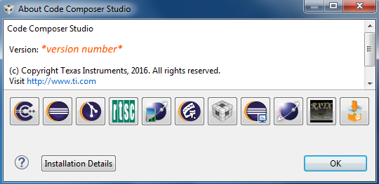
Make sure CCS is installed. You can find version info in the menu: Help → About Code Composer Studio
Make sure the correct SDK is installed. If it is installed to the default directory it should be located here:
C:\ti\simplelink_<device>_sdk_x_xx_xx_xxRun the
setup_sensor_controller_studio_xxx.exedownloaded from the link above and install.Open SCS and click
Updates→Check for Updates. If any new patches are available, clickUpdates→Manage Updates...and apply all new patches. Note that the picture below is only used as an example. You may have a newer version, and there may be no patches available.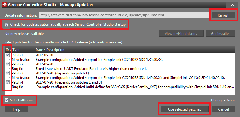
Connect LaunchPad
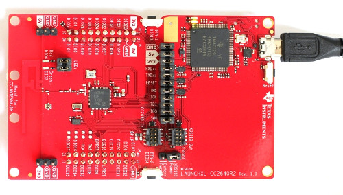
Simply connect the micro-USB cable from your computer to the LaunchPad as shown in the figure below:
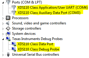
When the LaunchPad is connected, the Windows Device Manager (Start → Run → mmc devmgmt.msc → Ok) should show you the following devices connected:
Task 1 – Set up Project in SCS
You will now configure the ADC Window Monitor example code in SCS and import
the pre-made project into CCS. These are the steps that will be covered in more
details in the sub-chapters below:
- Configure the SCS example project for your device.
- Generate the Sensor Controller driver from the SCS project.
- Import the premade CCS project specification which will import these files:
- Main source example file that show how to integrate a Sensor Controller driver. This file is pre-made and is not part of the generated Sensor Controller driver.
- Sensor Controller driver.
- Sensor Controller driver framework.
Configure the Sensor Controller Example Project
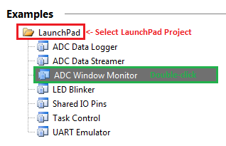
- Open SCS and double-click on the "ADC Window Monitor" LaunchPad example
project as shown in the figure below.
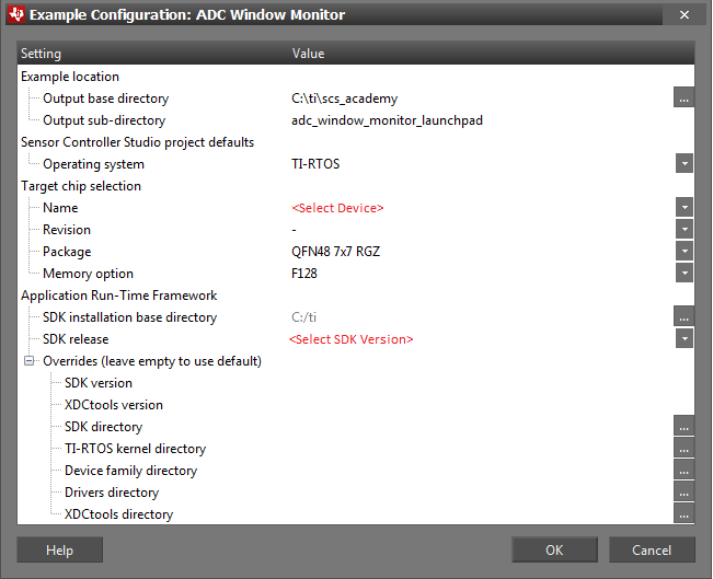
Now an Example Configuration Window will appear (refer to figure below). Do as follows:
- Select Target chip device name.
- Select correct SDK release.
- Change Output base directory to
C:\ti\scs_academy. - Your settings should match the screen shot below.
When the project is opened in SCS, the main source project and IDE project
files will automatically be populated into the output base directory. The
default path here is your documents folder
C:\Users\<your user>\Documents\Texas Instruments\Sensor Controller Studio\examples
where <your user> is your windows user name (%USERPROFILE%).
Generate the Sensor Controller Driver
- Go to the Code Generator Pane in SCS (CTRL+G) and press Generate driver source code.
- Verify that the driver is generated successfully in the event log. Then press View output directory (button is located at the bottom right corner).
What does Sensor Controller Studio Generate?(multiple correct answers)
SCS generates the SCIF driver and framework. Example projects included with
SCS are based on pre-made code which resides in its own example directory in
the installation directory. Each example project includes hard-coded examples
of simple main application source files (main.c/main_tirtos.c) along with
project files for both CCS and IAR.
Never open Sensor Controller Studio example projects directly from the installation directory. You should instead always open example projects from within Sensor Controller Studio. Doing modifications to an example project which were opened from the installation directory would be permanent. Sensor Controller Studio uses these files to restore examples in your base output directory, allowing you to always restore the original example project.
To integrate a driver into your custom application you need to create your own
main application source file (running on the main application processor). You
can use the SCS examples as a reference and starting point. The Sensor
Controller firmware image is found in the driver file scif.c. A more human-
readable format of the Sensor Controller assembler source code is available in
the assembler listing file sce.lst.
Import to Code Composer Studio
Do the following:
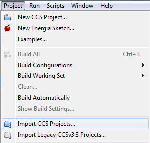
Open CCS and press Project → Import CCS Project
Select
C:\ti\scs_academy\adc_window_monitor_launchpadas the search- directory. This is the SCS project output base directory, which was set in the example configuration.Select
adc_window_monitor_launchpad_tirtosproject and press Finish.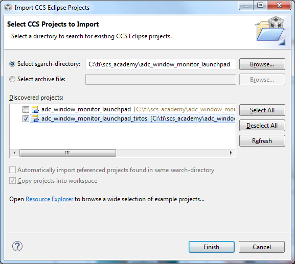
Compile the project. Press the hammer icon, or right click your project in the Project Explorer window then click
Build Project, to build in CCS.Verify that the build completes without errors.
Configure the debugger connection
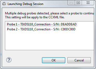
The correct debugger type (XDS110 for LaunchPad) is selected by default when you import the project. If more than one debugger of the same type connected, the GUI will query which debugger you want to use. Simply click on the debugger of choice and press OK.
If the debugger connection has already been configured, but you want to change to a different debugger connection, see instructions below for how this can be changed manually.
Make sure you only have one debugger of the same type connected when checking the serial number.
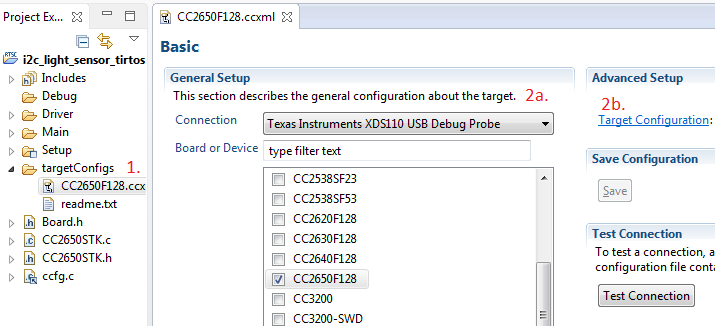
- Open the file
targetConfigs/CC2650F128.ccxml. - Change the connection to
XDS110 USB Debug Probeif needed. - Click on
Target Configuration
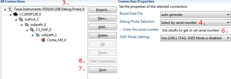
- Click on the top-level node (XDS110 USB Debug Probe)
- Choose 'Select by serial number'
- Start command prompt and call
c:\ti\ccs\ccs_base\common\uscif\xds110\xdsdfu.exe -eto enumerate the connected debugger. This will give you the serial number of the device.
C:\ti>c:\ti\ccs\ccs_base\common\uscif\xds110\xdsdfu.exe -e

USB Device Firmware Upgrade Utility
Copyright (c) 2008-2014 Texas Instruments Incorporated.  All rights reserved.

Scanning USB buses for supported XDS110 devices...


<<<< Device 0 >>>>

VID: 0x0451    PID: 0xbef3
Device Name:   XDS110 with CMSIS-DAP
Version:       2.2.4.2
Manufacturer:  Texas Instruments
Serial Num:    0000FF01
Mode:          Runtime

Found 1 device.

C:\ti>
Finding XDS110 serial number- Insert the serial number. Above it's
0000FF01. - Save the settings.
- Test the connection.
- Do this for both the
Appand theStackprojects.
You can also change the serial number to something easier to remember, or in case two debuggers have the same serial number.
C:\ti>c:\ti\ccs\ccs_base\common\uscif\xds110\xdsdfu.exe -m

USB Device Firmware Upgrade Utility
Copyright (c) 2008-2015 Texas Instruments Incorporated.  All rights reserved.

Scanning USB buses for supported XDS110 devices...


<<<< Device 0 >>>>

VID: 0x0451    PID: 0xbef3
Device Name:   XDS110 with CMSIS-DAP
Version:       2.2.4.2
Manufacturer:  Texas Instruments
Serial Num:    BADEABBA
Mode:          Runtime

Switching device into DFU mode.

C:\ti>c:\ti\ccs\ccs_base\common\uscif\xds110\xds110\xdsdfu.exe -s ABCDEF01 -r

USB Device Firmware Upgrade Utility
Copyright (c) 2008-2015 Texas Instruments Incorporated.  All rights reserved.

Scanning USB buses for supported XDS110 devices...

Setting serial number to "ABCDEF01"...

c:\ti>
Optionally change the serial numberTask 2 - Download and Debug with CCS
- Make sure that your HW is connected as instructed earlier in this guide.
- Press the Debug button (bug icon) or press F11 to start the debug session.
- Then press Resume (F8) to allow the code to run. The ADC will
sample the configured input pin (DIO23) at an interval and will notify the main
application processor if the measured/converted ADC input value change to
either below or above a set window threshold. The main application processor
will read out the result and set:
- Red LED (DIO6) if ADC input > high threshold.
- Green LED (DIO7) if ADC input < low threshold.
Breakpoints and source browsing in CCS
- In main_tirtos.c set breakpoints inside the two if statements as shown below in CCS by double clicking the desired lines or pressing CTRL+SHIFT+B.
// Wait for an ALERT callback
Semaphore_pend(Semaphore_handle(&semScTaskAlert), BIOS_WAIT_FOREVER); // Waiting for alert from Sensor Controller

// Clear the ALERT interrupt source
scifClearAlertIntSource();

// Indicate on LEDs whether the current ADC value is high and/or low
if (scifTaskData.adcWindowMonitor.output.bvWindowState & SCIF_ADC_WINDOW_MONITOR_BV_ADC_WINDOW_LOW) {
    PIN_setOutputValue(hLedPins, Board_GLED, 1);    // Set breakpoint here (Ctrl+Shift+B)
} else {
    PIN_setOutputValue(hLedPins, Board_GLED, 0);
}
if (scifTaskData.adcWindowMonitor.output.bvWindowState & SCIF_ADC_WINDOW_MONITOR_BV_ADC_WINDOW_HIGH) {
    PIN_setOutputValue(hLedPins, Board_RLED, 1);    // Set breakpoint here (Ctrl+Shift+B)
} else {
    PIN_setOutputValue(hLedPins, Board_RLED, 0);
}
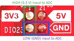
- Now run the application (F8) and alternate the ADC input (DIO23)
between High (3V3) and low (GND) and observe which breakpoint is hit in the
code. Press resume (F8) after the breakpoint is hit to allow the
code to resume from halt. The picture below show you how to connect the ADC
input to high or low with a jumper or wire.
- Find the address of the scifTaskData struct. Tips: press CTRL+H for advanced search options in CCS.
Quiz
Where is the variable scifTaskData.adcWindowMonitor.output.bvWindowState located?
Can the Sensor Controller access the Main application RAM?
- Find out in which context the scTaskAlertCallback function is called.
Quiz
The HWI function hwiTaskAlert will post the semaphore (semScTaskAlert), the application is pending on this semaphore. Which event (from the Sensor Controller) will trigger the Hardware Interrupt (HWI) hwiTaskAlert handler function?
- Terminate the adc_window_monitor_launchpad project (Ctrl + F2 or red square icon).
Task 3 - Download and Debug with SCS
In this task you will debug the Sensor Controller task directly from Sensor
Controller Studio. Sensor Controller Studio taking over the role of the System
CPU application and interacting with the Sensor Controller task through the
debugger. More detailed information about this can be read in the SCS Help
viewer (press F1 in SCS and go to Task Testing Panel). We will
now debug the Sensor Controller task without any application running on the
main application processor.
Quiz
Is it currently possible to debug both code on the main application processor and the Sensor Controller at the same time (concurrently)?
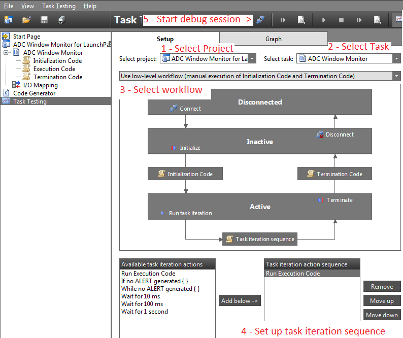
- In SCS, go to the Task Testing panel by clicking on the tab or pressing Ctrl + T.
- In the Task Testing window, if you have multiple projects open; select the ADC Window Monitor for LaunchPad project like shown in the screen shot below.
- Be sure to select
low-level workflowbefore connecting to target.
When taking over the role of the System CPU application during task testing
and debugging, SCS cannot interact with the Sensor Controller in real-time,
and also has no knowledge of what a task iteration (during task testing)
actually is. The sequence of events that will occur during a task iteration
must therefore be specified, and this is done by listing a sequence of
actions. In this example you can simply set up Run Execution Code.
Verify your Task Testing window matches the screenshot below before starting task testing.
- Start a debug session by connecting to target (F12).
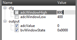
- Set the threshold values in the cfg RAM variables as shown in the screen shot
below. These values are set by the main application and therefore needs to be
set manually in task testing.
- Run the initialization code once (F6).
- Run task iterations continuously (F5).
- Experiment and adjust the input level on the ADC input. You can use a jumper and connect the DIO23 pin to 3V3 and GND. Observe the adcValue and bvWindowState in the graph window as in the screen shot below.
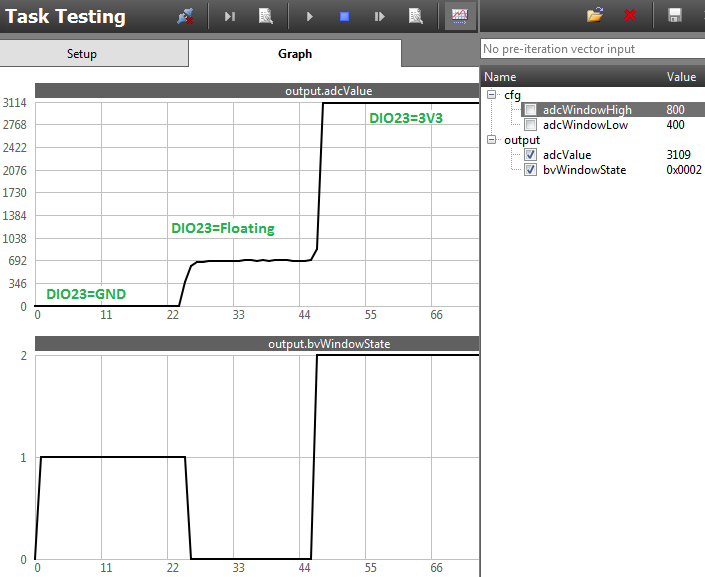
The icons and hot keys for debugging alter meaning and form during each step which means the hot keys, for example F6, have different actions during the different phases. This makes it easier to restart the execution code as you can press F6 twice or press the same icon twice to run termination code and initialization code again before starting the execution code again.
Now you will start a task testing (assembler code) debugging session:
- When you are satisfied press stop (F6).
- Run the termination code (F6).
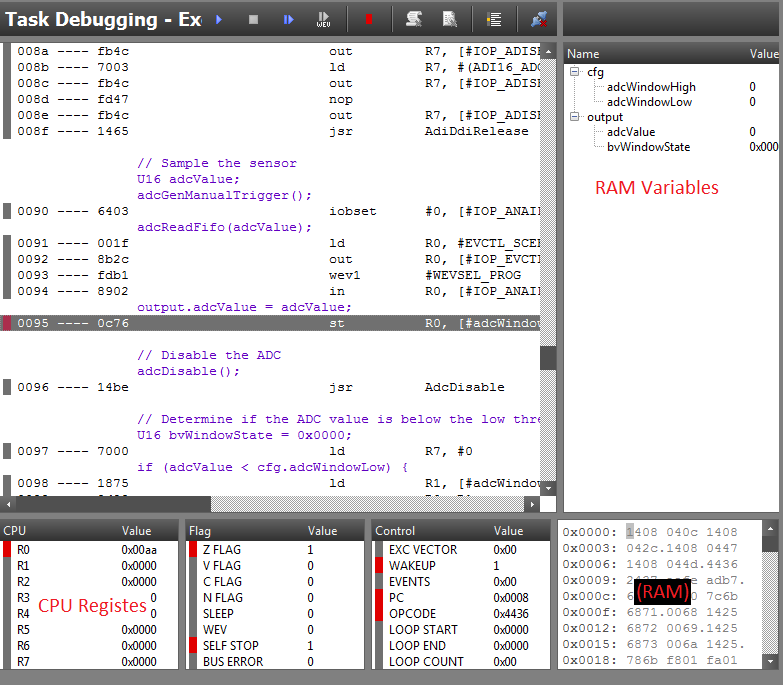
- Run the initialization code once (F11).
- Start a debug session of one task iteration (CTRL + F11).
- Place a breakpoint as shown in the image below where the converted ADC input value is stored to the RAM variable output.value (F9).
- Press run continuously (F5).
- Now you should hit the breakpoint. Single step in the code by pressing
F11 and observe the new value being loaded into output.adcValue
(seen on right pane). Change the input ADC value, repeat the process and
verify the new measured input voltage.
Task 4 - Understand
In this task you will try to grasp the basic flow of the ADC Window Monitor example program and solve a quiz to make sure you understand the concepts. Code from the Sensor Controller or the main application is presented in the format shown in the table below.
| Code Context | Core | Formatted Example | Format |
|---|---|---|---|
| Application Processor (AP) | 32-bit Cortex-M | scifStartRtcTicksNow() |
Code (Italic) |
| Sensor Controller Processor (SCP) | 16-bit RISC | fwScheduleTask(1); |
Code |
Program Flow (ADC Window Monitor for LaunchPad)
Here is a brief step-by-step list on the program flow for the ADC Window Monitor project:
Boot and Initialization
1) The complete application including the Sensor Controller driver will be loaded as a flash image on to the device.
2) On boot, the main() function will configure a task, initialize a
semaphore and boot the TI-RTOS kernel (BIOS_start()).
3) In the task function (taskFxn) everything needed for the Sensor
Controller driver will be configured:
- (1) Construct Sensor Controller framework semaphore.
- (2) Interrupt handlers are registered.
- (3) Load Sensor Controller program image to the Sensor Controller RAM and configure the complete driver setup which includes IO Mapping, Domain Clocks, control and data variables, HWI's and more. For more details refer to the source code.
- (4) Schedule periodic wakeup interval for the Sensor Controller.
- (5) Write upper and lower window limits directly to Sensor Controller RAM.
(6) The Sensor Controller task is started and the initialization code will run once.
  // Initialize the Sensor Controller
  scifOsalInit();                                         // (1)
  scifOsalRegisterCtrlReadyCallback(scCtrlReadyCallback); // (2)
  scifOsalRegisterTaskAlertCallback(scTaskAlertCallback); // (2)
  scifInit(&scifDriverSetup);                             // (3)
  scifStartRtcTicksNow(0x00010000 / 8);                   // (4)

  /*  Configure and start the Sensor Controller's
  *   ADC window monitor task (not to be confused with RTOS tasks)
  */
  scifTaskData.adcWindowMonitor.cfg.adcWindowHigh = 800;  // (5)
  scifTaskData.adcWindowMonitor.cfg.adcWindowLow  = 400;  // (5)
  scifStartTasksNbl(BV(SCIF_ADC_WINDOW_MONITOR_TASK_ID)); // (6)
Program Loop Running
4) TI-RTOS task will then pend on the semaphore semScTaskAlert
(device enter sleep/standby).
5) The Sensor Controller wakes up every 125 ms (interrupt from RTC
channel 2 compare event) and runs the execution code as scheduled
(fwScheduleTask(1);).
6) The execution code will trigger an ADC conversion. If the ADC value is
below or above the set window thresholds it wakes up the TI-RTOS task
(fwGenAlertInterrupt();).
7) The triggered HWI calls scTaskAlertCallback which posts the
semScTaskAlert semaphore.
8) The TI-RTOS task taskFxn iterate once through the while-loop.
9) LED's are set/cleared and the interrupt source cleared.
10) Repeat steps 5) to 9) forever (while-loop).
Review SCS Project Panes
Review the open project (ADC Window Monitor for LaunchPad) in SCS and review the project panels. Press F1 and navigate to the Project Panel section where you find all the details for every panel in the project. The table below lists all the project panels with a very short description.
Termination Code will only run once when task is stopped by the application
processor (scifStopTasksNbl()) or at the end of a single iteration for all
task code blocks (scifExecuteTasksOnceNbl()). In the "ADC Window Monitor"
example the termination code never runs and is therefore left blank.
| Panel (Tab) | Description |
|---|---|
 |
Define project name, location, chip/OS configuration, description and add tasks. |
 |
CC13xx/CC26xx devices only: Configure power and clock modes for various parts of the project. |
 |
Configure task name, description and resources for every Task in the project. |
 |
Code that will run once when task is initialized. |
 |
The Execution Code will run when scheduled by fwScheduleTask().Is only available if the RTC-Based Execution Scheduling resource is enabled. |
 |
The Event Handler Code will run when its corresponding event is triggered. Is only available if any Event Trigger resources are enabled, e.g. GPIO Event Trigger. |
 |
Termination code run once on task exit or never if the task runs forever. |
 |
Configure I/O functions to I/O pins. |
 |
Compile task code and generate application framework. |
 |
Test and debug a single Sensor Controller task. |
 |
Rune-Time Logging panel for evaluating and optimizing performance. |
Review Sensor Controller Task Code
Browse the different task codes (initialization, execution, event handler, termination) and answer the following quiz.
Quiz
How many times will Initialization Code run in the adc_window_monitor_launchpad example?
(Hint: scifCtrlTasksNbl() in scif_framwork.c)
How often will Execution Code run in the adc_window_monitor_launchpad example?
(Hint: fwScheduleTask() procedure in SCS)
How often will Termination Code run in the adc_window_monitor_launchpad example?
(Hint: fwScheduleTask())
Great Work!
You completed first module and demonstrated the Sensor Controller!
Below is two optional bonus tasks that will let you get more hands on and learn important key concepts about the Sensor Controller and ADC.
Task 5 - Bonus Tasks (Low to Intermediate Level)
These tasks will let you get hands on and modify Sensor Controller task code, modify application code (TI-RTOS) as well as discuss ADC accuracy.
Bonus Task 1 - Read and Correct ADC Value
In this task you will read the raw ADC value directly from the Sensor
Controller RAM in the TI-RTOS main application and correct for ADC gain error
and ADC offset error. The ADC offset and gain error are calculated in
production test and stored in FCFG1. The driverlib file aux_adc.h contains
functions that can retrieve and apply these corrections to a raw ADC
conversion result as well as reverse a corrected value back to the equivalent
raw ADC result value. These functions must be run in the main application as
the computations are too demanding for the Sensor Controller processor. For
example, if the driver needs to trigger on a precise ADC value threshold you
can calculate the corresponding raw value in the main application and write
the value directly to the Sensor Controller RAM. You will do this in the
exercise Configure Microvolt Threshold
below.
Read ADC Value Directly from Sensor Controller RAM
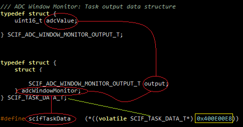
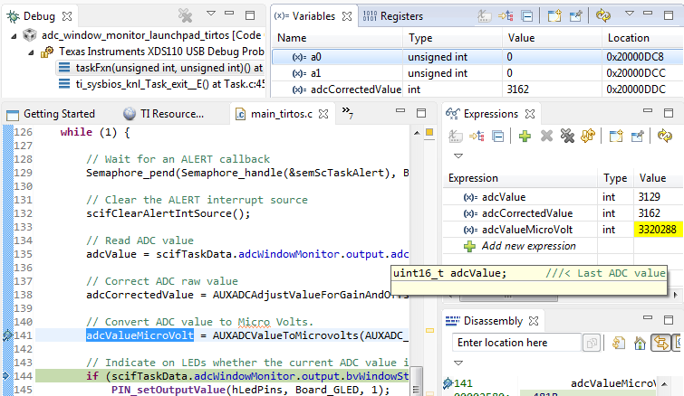
The framework (scif.h) defines structs for all the Sensor Controller RAM
variables. Try to read the raw adc result after an ADC conversion takes place.
Simply access the correct sub-members of the scifTaskData struct. The figure
below will guide you to the correct struct member variable.
 // Wait for an ALERT callback
 Semaphore_pend(Semaphore_handle(&semScTaskAlert), BIOS_WAIT_FOREVER);

 // Clear the ALERT interrupt source
 scifClearAlertIntSource();

 // Read ADC value
 int32_t adcValue = (int32_t) scifTaskData.adcWindowMonitor.output.adcValue;  // Set breakpoint here (CTRL+SHIFT+B.)
- After you have written code to read the raw ADC value, set breakpoint at the line where the value is read (CTRL+SHIFT+B.)
- Compile, download and debug in CCS by pressing F11.
- When ready to run, press F8 to run to breakpoint.
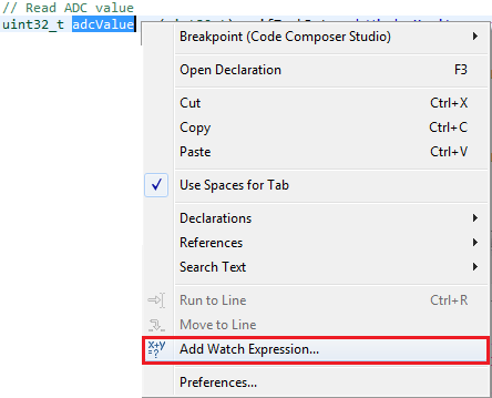
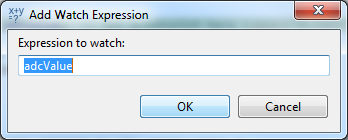
- After the the breakpoint is hit, right-click on the read variable and press Add Watch Expression...
- Press ok on the dialog box.
- Single step (over) F6 and observe the value.
- Change the ADC input voltage and repeat the steps above to verify correct behavior.
Correct Raw ADC Value and Convert to Microvolts
In this sub-task you will correct the raw ADC value and modify the main application code to set/clear LED's depending on threshold values given in microvolt. Direct links for specific devices are given below:
Review the driverlib API documentation for
aux_adcwhich contains all the functions you need to solve this task.The driverlib API can be found under the docs folder in your SimpleLink SDK installation, i.e.
<SDK>/docs/driverlib_cc13xx_cc26xx/docs_overview_driverlib_cc13xx_cc26xx.html.Or, you can find the driverlib API in the TI Resource Explorer. For example, the SimpleLink CC13x0 SDK would have the following path:
Software→SimpeLink CC13x0 SDK - v:*version*→Documents→DriverLib→Driverlib Documentation
- Correct the Raw ADC value (offset error and gain error).
- Convert the corrected ADC value to microvolts.
- Compile, download and debug (F11).
- Add watch expression for both the raw adc value and the corrected version. Single step in debug mode and observe the delta.
#include <ti/devices/DeviceFamily.h>
#include DeviceFamily_constructPath(driverlib/aux_adc.h)

void taskFxn(UArg a0, UArg a1) {

    int32_t adcOffset = AUXADCGetAdjustmentOffset(AUXADC_REF_FIXED);
    int32_t adcGainError = AUXADCGetAdjustmentGain(AUXADC_REF_FIXED);
    int32_t adcValue, adcCorrectedValue, adcValueMicroVolt;

    PIN_Handle hLedPins;

    // Enable LED pins
    hLedPins = PIN_open(&ledPinState, pLedPinTable);

    // Initialize the Sensor Controller
    scifOsalInit();
    scifOsalRegisterCtrlReadyCallback(scCtrlReadyCallback);
    scifOsalRegisterTaskAlertCallback(scTaskAlertCallback);
    scifInit(&scifDriverSetup);
    scifStartRtcTicksNow(0x00010000 / 8);

    // Configure and start the Sensor Controller's ADC window monitor task (not to be confused with OS tasks)
    scifTaskData.adcWindowMonitor.cfg.adcWindowHigh = 800;
    scifTaskData.adcWindowMonitor.cfg.adcWindowLow  = 400;
    scifStartTasksNbl(BV(SCIF_ADC_WINDOW_MONITOR_TASK_ID));

    // Main loop
    while (1) {

        // Wait for an ALERT callback
        Semaphore_pend(Semaphore_handle(&semScTaskAlert), BIOS_WAIT_FOREVER);

        // Clear the ALERT interrupt source
        scifClearAlertIntSource();

        // Read ADC value
        adcValue = scifTaskData.adcWindowMonitor.output.adcValue;

        // Correct ADC raw value
        adcCorrectedValue = AUXADCAdjustValueForGainAndOffset((int32_t) adcValue, adcGainError, adcOffset);

        // Convert ADC value to Microvolts.
        adcValueMicroVolt = AUXADCValueToMicrovolts(AUXADC_FIXED_REF_VOLTAGE_NORMAL,adcCorrectedValue);

        // Indicate on LEDs whether the current ADC value is high and/or low
        if (scifTaskData.adcWindowMonitor.output.bvWindowState & SCIF_ADC_WINDOW_MONITOR_BV_ADC_WINDOW_LOW) {
            PIN_setOutputValue(hLedPins, Board_GLED, 1);
        } else {
            PIN_setOutputValue(hLedPins, Board_GLED, 0);
        }
        if (scifTaskData.adcWindowMonitor.output.bvWindowState & SCIF_ADC_WINDOW_MONITOR_BV_ADC_WINDOW_HIGH) {
            PIN_setOutputValue(hLedPins, Board_RLED, 1);
        } else {
            PIN_setOutputValue(hLedPins, Board_RLED, 0);
        }

        // Acknowledge the alert event
        scifAckAlertEvents();
    }

} // taskFxn
Configure Microvolt Threshold
Now you will configure new threshold values based on microvolt. Convert from
microvolt to raw value (AUXADCMicrovoltsToValue) and calculate the raw
threshold values with corrections for gain error and offset error
(AUXADCUnadjustValueForGainAndOffset).
- Define new thresholds for the window monitor:
- Window High = 0.8 Volts (800000 microvolts)
- Window Low = 0.4 Volts (400000 microvolts)
- Calculate the corresponding raw values and write these to the appropriate Sensor Controller configuration variables.
- Compile, download and debug (F11).
- If you have an external power supply you can apply voltages to the ADC input (DIO23) to verify if the Sensor Controller window monitor triggers on the expected voltage values.
    /* Set threshold based on microVolt */
    int32_t adcThresholdLowMicro = 400000;      // 0.4 Volt
    int32_t adcThresholdHighMicro = 800000;     // 0.8 Volt

    int32_t adcThresholdLow = AUXADCMicrovoltsToValue(AUXADC_FIXED_REF_VOLTAGE_NORMAL, adcThresholdLowMicro);
    int32_t adcThresholdHigh = AUXADCMicrovoltsToValue(AUXADC_FIXED_REF_VOLTAGE_NORMAL, adcThresholdHighMicro);

    int32_t adcThresholdLowRaw = AUXADCUnadjustValueForGainAndOffset(adcThresholdLow, adcGainError, adcOffset);
    int32_t adcThresholdHighRaw = AUXADCUnadjustValueForGainAndOffset(adcThresholdHigh, adcGainError, adcOffset);

    // Configure and start the Sensor Controller's ADC window monitor task (not to be confused with OS tasks)
    scifTaskData.adcWindowMonitor.cfg.adcWindowHigh = adcThresholdHighRaw;
    scifTaskData.adcWindowMonitor.cfg.adcWindowLow  = adcThresholdLowRaw;
    scifStartTasksNbl(BV(SCIF_ADC_WINDOW_MONITOR_TASK_ID));
Bonus Task 2: GPIO Event Handler
Now you will change the Sensor Controller driver from being a window monitor
to trigger on either low or high input value on DIO23 (ADC input). For this
you will use the GPIO Event Trigger resource in Sensor Controller. This will
cause the Sensor Controller driver to trigger on interrupt instead of
scheduling execution code and therefore all the content in the execution code
can be removed. In the default ADC Window Monitor example project
(main_tirtos.c), periodic wakeups based on RTC compare events is configured:
/* Wake up Sensor Controller every 125 ms
 * 1 second (0x00010000) / 8 = 125 ms. */
scifStartRtcTicksNow(0x00010000 / 8);
RTC configuration in application code
Every time the Sensor Controller wakes up it will check if a task is scheduled to run its execution code. If the previously run Sensor Controller code scheduled an execution with argument 1:
/* Schedule execution at the next Sensor Controller
 * RTC scheduled wakeup. */
fwScheduleTask(1);
Scheduling of RTC wakeup in Sensor Controller Task code
If there is only execution code in the Sensor Controller driver and every
execution task is scheduled to run at every 10 wakeups (fwScheduleTask(10);)
the Sensor Controller would wakeup 10 times and do nothing else except waste
energy. In this case you should reconfigure the wakeups
(scifStartRtcTicksNow(0x00010000);) and schedule the execution code to run
at every wakeup (fwScheduleTask(1);). But in this task you do not need
scheduling or the execution code as the event handler code is triggered to run
directly after every interrupt. Let's start the task with a fresh copy of the
ADC Window Monitor example project.
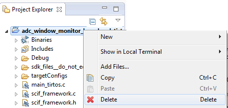
- Delete the modified ADC Window Monitor project in CCS and SCS:
- To delete a project in CCS, right-click on the project, then press Delete
and OK.
- Delete the physical project stored in
C:\ti\scs_academy\adc_window_monitor_launchpad. If you want to save the work for future references simply rename the folder instead. - Close the project in SCS.
- To delete a project in CCS, right-click on the project, then press Delete
and OK.
- Open clean ADC Window Monitor for LaunchPad project
- Open the ADC Window Monitor project in SCS as you did in the start of this training. Now a fresh copy of the project will be spawned at the set output base directory.
- Import the project in CCS.
- In main_tirtos.c: disable the Sensor Controller periodic wakeups:
// scifStartRtcTicksNow(0x00010000 / 8);
Modify the Sensor Controller driver:
- Open task resources by navigating to the Task Panel for the ADC Window Monitor.
- Press the help viewer button on the GPIO Event trigger. Review the help text.

- In task panel under the Task resources, enable "Digital Input Pins", "System
CPU Alert" and "GPIO Event Trigger":
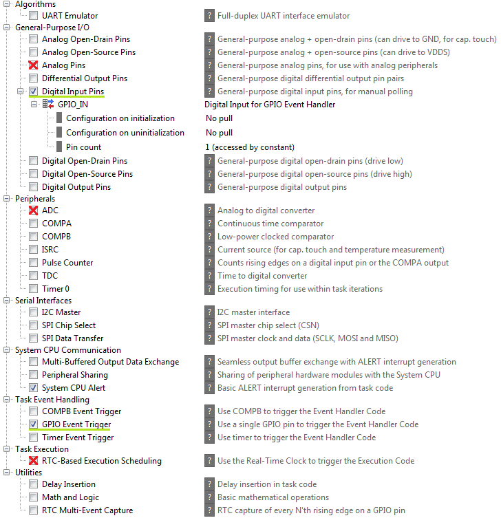
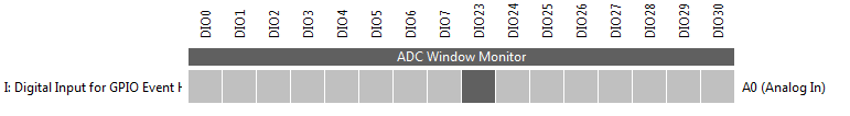
- Go to the I/O Mapping tab and select DIO23 as input.
- In initialization code, set up gpio trigger to trigger on high match
(
evhSetupGpioTrigger). - Copy the behavior from the execution code into the event handler code so that the application defined in main_tirtos.c will behave as before. Also set up the next GPIO trigger.
- Remove all contents in execution code.
- Generate the Sensor Controller driver (CTRL+G).
Compile run and test project in CCS (F11).
Initialization Code:
output.bvWindowState = 0;
evhSetupGpioTrigger(0, AUXIO_I_GPIO_IN, 1, EVH_GPIO_TRIG_ON_MATCH);
Event Handler Code:
if(output.bvWindowState == BV_ADC_WINDOW_LOW) {
    output.bvWindowState = BV_ADC_WINDOW_HIGH;
    // Set up the next interrupt trigger
evhSetupGpioTrigger(0, AUXIO_I_GPIO_IN, 0, EVH_GPIO_TRIG_ON_MATCH);
} else {
    output.bvWindowState = BV_ADC_WINDOW_LOW;
    // Set up the next interrupt trigger
    evhSetupGpioTrigger(0, AUXIO_I_GPIO_IN, 1, EVH_GPIO_TRIG_ON_MATCH);
}
fwGenAlertInterrupt();