SimpleLink™ RCL and Basic RX/TX#
Texas Instruments
30 ~ 60 min read
Introduction#
The purpose of this exercise is to familiarize the users with the Radio Control Layer (RCL) driver and Code Composer Studio, by importing existing RX & TX example applications.
This basic level tutorial is simply a step by step instruction on how to get one of the provided FreeRTOS SimpleLink Basic RX/TX examples running in Code Composer Studio.
Prerequisites#
Hardware#
2 x SimpleLink CC2340R5 LaunchPad Target
2 x SimpleLink™ LaunchPad™ XDS110 Debugger
2 x USB cable
Group training additional requirements#
Make sure to always use your designated frequency, to avoid interfering with other students’ operations.
Warning
If you are part of a group training, please ask the instructor for a unique frequency to use during this lab.
For simplicity, it is possible to use a base frequency, allocate a running number to each of the students and have each student multiply their number by 100 kHz channel changes.
Software#
Code Composer Studio 12.3 or IAR 9.32.1 installed with support for CC23xx devices.
SIMPLELINK-LOWPOWER-F3-SDK SimpleLink™ Software Development Kit
FreeRTOS download zip file
Documentation#
Radio Control Layer API Documentation
Radio Control Layer (RCL)#
Overview of RCL#
The RCL module provides access to the radio for LPF3 devices. It offers a high-level interface for command execution while also ensuring the lowest possible power consumption by providing automatic power management that is fully transparent to the application. Conceptually, the RCL module can be divided into RCL “High” and RCL “Low”. RCL High takes care aspects such as command scheduling, programming the LRF (Radio IP) images, programming the SYSTIMER (system timer) for a wake-up, etc., while RCL Low takes care of protocol specific operations through command handlers which deal with everything that occurs during the command life cycle. Finally, to ensure that critical sections are reduced and timing constraints are met, the RCL module uses three different priority hardware interrupts (Hwi) depending on the operation.
Scheduling Hwi: This is the lowest priority interrupt. When the client submits a command, the command is enqueued in whatever context the client has called it, and the scheduling Hwi is invoked. If the command is an immediate schedule command, then the command Hwi is invoked.
Dispatch Hwi: This Hwi checks if the command has completed and takes it out of circulation for possible reuse, it notifies the owner about the RCL and LRF events associated with the radio operation, and executes the callback (if there is one).
Command Hwi: This is the highest priority interrupt. It is in charge of bringing the radio into the desired state and invoking the handler state machine which loads the specific commands and parameters, and then starts the operation.
Packet Formatting Radio Control Layer#
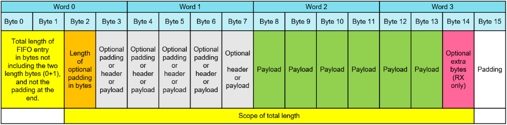
Transmitted and received packet entries must be compatible and stored in the LRF FIFOs format, regardless of the communication protocal used. The LRF FIFOs consists of a total of 16 bytes:
bytes |
Description |
|---|---|
0 - 1 |
total length of FIFO entry |
2 |
length of optional padding in bytes |
3 - 7 |
optional header, padding, or payload |
8 - N |
payload |
14+payload |
optional extra byte (RX only) |
15+payload |
padding |
The following rules apply to the internal packet format:
Word 0 shall always be aligned to a 32 bit address
Padding can be used by application to e.g. word align header, word align the payload or other points in the packet.
Required fields are: FIFO length (Bytes 0-1), padding length (Byte 2), and payload.
The optional padding must be continuous.
When it comes to the order in the FIFO, the optional padding is always followed by the header (if any), and the header is always followed by the payload.
In the case of fixed length or that the header fits in byte 3, then word 1 can be omitted.
The length field to be transmitted over the air must be embedded in the header written to the FIFO
Configurable padding (based on LRF settings) at the end of the entry which is emptied from the TX FIFO by the LRF in TX, and entered by the LRF into RX FIFO in RX.
API Overview#
The RCL driver documentation is installed as part of the SDK. To access it, please refer to your SDK installation folder. If you chose the default settings during the installation process, then the location would be similar to this:
C:\ti\simplelink_lowpower_f3_sdk_7_10_00_35\docs\rcl\html\index.html
For convenience, the key RCL Driver APIs for generic RX / TX testing are briefly listed here:
API Function |
Description |
|---|---|
RCL_init() |
Initializes the RCL driver state. Resets global state and initialize hardware. |
RCL_open() |
Initializes an RCL client instance. |
RCL_close() |
Closes client instance and deallocates open resources. |
RCL_Command_submit() |
Submit RCL command object to be scheduled for execution. |
RCL_Command_pend() |
Wait for a submitted command to complete. |
RCL_Command_stop() |
Sends the message to try to stop a command. When the function returns, the command may still be running. Depending on the stop type, the command may stop after some time. RCL_Command_pend may be used to wait for the command to finish. |
RCL_readRssi() |
Returns the last valid RSSI value or error status if the last obtained RSSI value is no longer valid. |
There are additional commands for declaring an RCL command as well as configuring them including scheduling, callbacks, timings, etc.
RX/TX Command Structure Description#
Let’s take a deeper look into the key members within the RCL command structure
for Tx (RCL_CmdNesbPtx) and Rx (RCL_CmdNesbPrx). The syncWord and
rfFrequency are shared parameters between the two since both are needed to
establish communications. txBuffer and rxBuffer are included which is a
linked list of packets to transmit and receive. Tx contains a txPower member
function to indicate the transmit power, and Rx contains two syncWords
(syncWordA, syncWordB) so that one or more syncWords can be detected to
establish communication.
Other generic RCL parameters that are used primarily
on the receiving end, include lastTimestamp to show when the last received
packet arrived, timestampValid to check for valid lastTimestamp, lastRssi
to indicate the RSSI of the last received packet, nRxNok to indicate number of
packets received with CRC error, and nRxOk to indicate number of of
correctly received packets.
Preparation#
Initial Setup#
If your system is already setup skip this part and go directly to the next section.
All the collaterals are available on TI website.
Download and Install the SDK found in the software section above.
Download and Install CCS found in the software section above.
Download FreeRTOS found in the software section above. Follow the “Using FreeRTOS with CCS” guide for installation process.
Find The Serial Number#
Disconnect all the LaunchPads™ you may have connected to your computer leaving only the SimpleLink CC2340R5 LaunchPad.
Open a command prompt and run the
xdsdfu.execommand for your CCS version, e.g.<CCS_INSTALL_DIR>\ccs\ccs_base\common\uscif\xds110\xdsdfu.exe -e. This will enumerate all the attached XDS110 debug probes. This should result in output like the following:
C:\>c:\ti\ccs1210\ccs\ccs_base\common\uscif\xds110\xdsdfu.exe -e

USB Device Firmware Upgrade Utility
Copyright (c) 2008-2019 Texas Instruments Incorporated.  All rights reserved.

Scanning USB buses for supported XDS110 devices...


<<<< Device 0 >>>>

VID: 0x0451    PID: 0xbef3
Device Name:   XDS110 Embed with CMSIS-DAP
Version:       3.0.0.22
Manufacturer:  Texas Instruments
Serial Num:    LS420073
Mode:          Runtime
Configuration: Standard

Found 1 devices.

C:\>
Configure Serial Number#
Use this section when multiple Launchpads are being used at the same time or when it may be necessary to set or unset the selected debug probe.
Open the targetConfigs folder in your imported CCS projects and click on the .ccxml file.
Open the Advanced pane or click on
Target Configurationin the Advanced Setup section.Choose the top-level debug entry which should open a
Connection Propertiessection to the right.From the
Debug Probe Selectiondropdown list, chooseSelect by serial numberand enter the serial number you have found here.
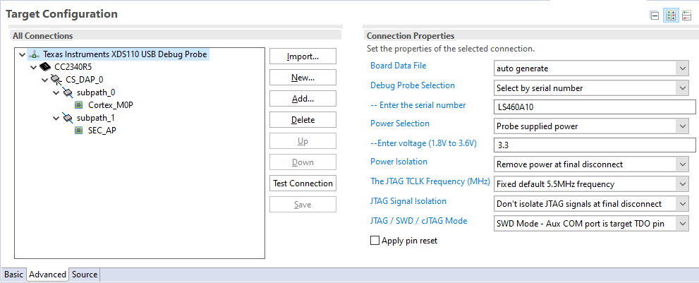
Target Configuration Section#
Basic RX/TX#
Follow these steps to import existing examples, rfPacketTx and rfPacketRX, into Code Composer Studio. When selecting SDK, make sure to select the SDK that relates to the device that is used.
Have both LaunchPads connected to the PC and powered on. Make sure that no other program is currently accessing the LaunchPads.
Open Code Composer Studio (CCS), then in the menu, select Project > Import CCS Projects
Select Browse and navigate to the location of the rfPacketTX and rfPacketRX examples within the SDK:
\examples\rtos\LP_EM_CC2340R5\prop_rf Select and import each example separately into your CCS workspace
Select the rfPacketTx project so that it has the [Active - Debug] status.
Configure the project by following the instructions in the
Configure Serial Numberfor one of your connected boards.Build the project by clicking on the hammer icon or right-click on the project and selecting Build Project. Wait until fully built then click on the green bug icon to begin flashing and debugging.
Exit debugger by pressing the Red Square. Repeat steps 5 - 7 for the rfPacketRx project.
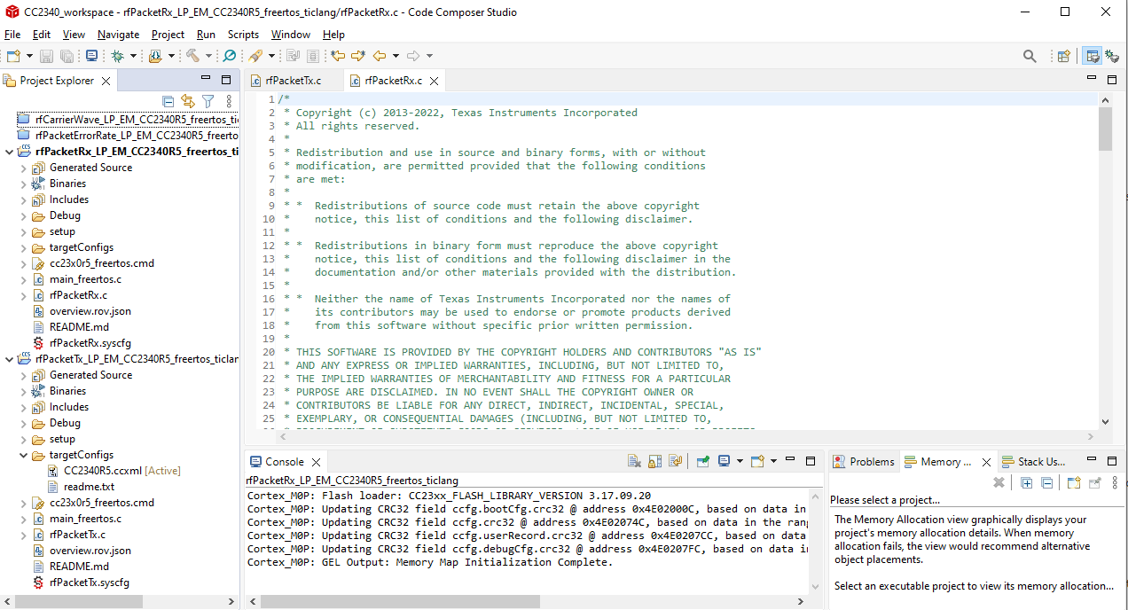
CCS Rx/Tx project#
Note
If Configure Serial Number steps were followed correctly, one LaunchPad will
have a green LED (TX: Transmitting packet) and the other will have a red LED
(RX: Receiving packet).
Modifying Examples#
Next we will begin modifying some of the parameters for transmitting and
receiving such as syncWord, PHY, rfFrequency, channel, packet interval,
packet length, and etc.
Open the rfPacketTx.c file within the rfPacketTx project or rfPacketRx.c file within the rfPacketRx project.
In the list of includes CTRL+click (windows) or CMD+click (macOS) on <ti/drivers/rcl/commands/generic.h> which will open up the generic RCL file where configuration parameters are located.
Under
RCL_CmdGenericTx_Default()andRCL_CmdGenericRx_Default()are where you can modify thesyncWord, frequency, buffer, max packet length, etc.
#define RCL_CmdGenericTx_Default()                          \
{                                                           \
    .common = RCL_Command_Default(RCL_CMDID_GENERIC_TX,     \
                                  RCL_Handler_Generic_Tx),  \
    .rfFrequency = 2440000000U,                             \
    .txBuffers = { 0 },                                     \
    .syncWord = 0x930B51ED,                                 \
    .txPower = {.dBm = 0, .fraction = 0},                   \
    .config = {                                             \
        .fsOff = 1,                                         \
        .reserved = 0,                                      \
    },                                                      \
}
#define RCL_CmdGenericRx_Default()                          \
{                                                           \
    .common = RCL_Command_Default(RCL_CMDID_GENERIC_RX,     \
                                  RCL_Handler_Generic_Rx),  \
    .rfFrequency = 2440000000U,                             \
    .rxBuffers = {0},                                       \
    .stats = NULL,                                          \
    .syncWordA = 0x930B51ED,                                \
    .syncWordB = 0x12345678,                                \
    .maxPktLen = 255,                                       \
    .config = {                                             \
        .repeated = 1,                                      \
        .disableSyncA = 0,                                  \
        .disableSyncB = 1,                                  \
        .discardRxPackets = 0,                              \
        .fsOff = 1,                                         \
        .reserved = 0,                                      \
    },                                                      \
}
In order to modify the PHY, right-click on the project and select Properties. Go to Build > Arm Compiler > Predefined Symbols. Under Pre-define NAME (-D), add (click on green + icon) the macro for the RCL settings you want to use.
Note
For this example, the defines are located in the rfPacketTx.c and rfPacketRx.c:
where USE_250KBPS_MSK and USE_250KBPS_MSK_FEC are the names that should be added.
#if defined(USE_250KBPS_MSK)
#include <setup/rcl_settings_msk_250_kbps.h>
#elif defined(USE_250KBPS_MSK_FEC)
#include <setup/rcl_settings_msk_250_kbps_fec.h>
#else
#include <setup/rcl_settings_ble_generic.h>
#endif
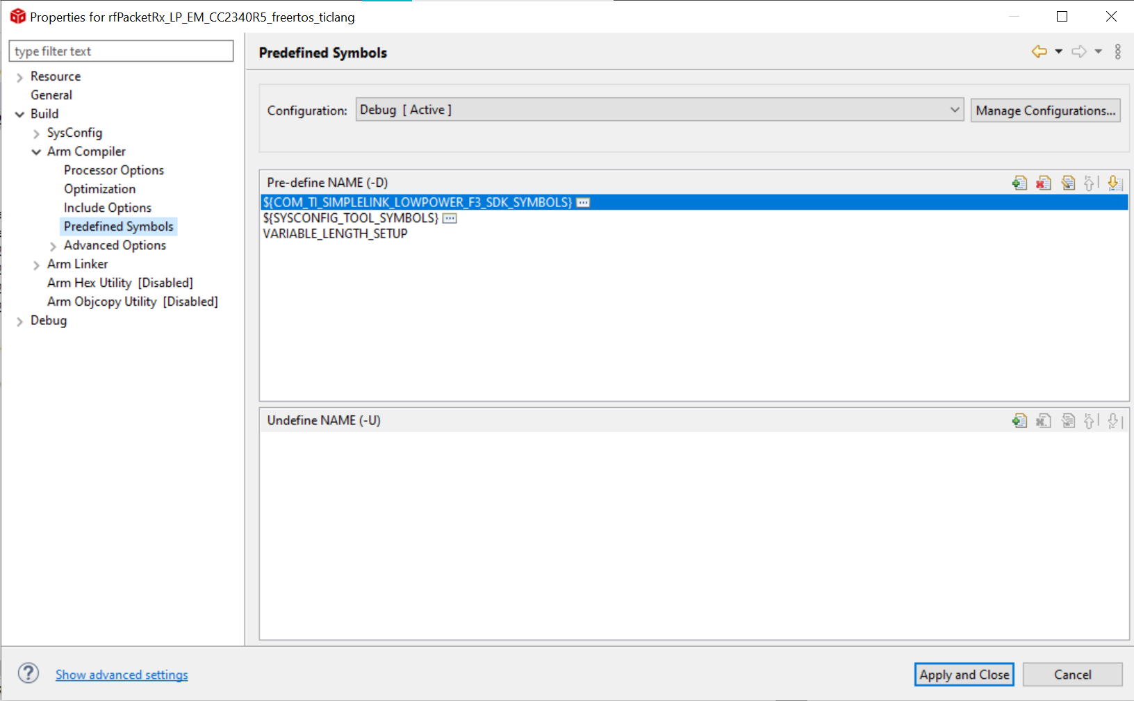
Properties location for Pre-define Symbols#
Other changes can be accomplished within rfPacketTx.c and rfPacketRx.c file (i.e. packet data, packet interval, power) in the “Define” sections.
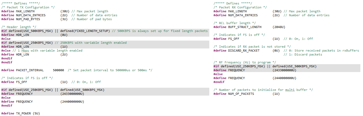
rfPacketTx and rfPacketRx Defines#
Note
Some parameters must be consistent between the Tx and Rx such as syncWord,
rfFrequency, and max packet length.
Modifying PHY will need to be accomplished for both Rx and Tx.
Next Steps#
This lab covers the basics of RCL, setting up a RF link between two CC2340R5 boards and modifications that can be made to Rx and Tx parameters through CCS. For more information, follow the references below to visit the various User’s Guides. The next lab will be a basic RF link through SmartRF Studio 8 and working with rfPacketErrorRate.
References#
SimpleLink CC2340R5 LaunchPad
SIMPLELINK-LOWPOWER-F3-SDK
Code Composer Studio
FreeRTOS
Using FreeRTOS with CCS
TI website
BLE5 Stack User’s Guide
Quick Start Guide
Radio Control Layer
PropRF User Guide