Zigbee Custom Device Types#
Texas Instruments
1 - 2 hours to complete
Introduction#
This lab modifies an existing on/off light example to generate other Zigbee device functionality, specifically a door lock and temperature sensor. In doing so it will highlight the necessary documentation, resources, and ZCL APIs involved so that users have the ability to develop other device types not shown.
Task 1: Importing the on/off light project and renaming files
Task 2: Finding the necessary ZBOSS ZCL8 documentation
Task 3: Changing the project’s ZCL8 APIs
Task 4: Testing the new device type
Task 5: Bonus functional device type
Zigbee is a component of the SimpleLink LowPower F3 Software Development Kit and is a complete Zigbee 3.0 software solution.
Note
Technical Support: For any questions you may have, please refer to the TI Zigbee & Thread E2E Forum.
Prerequisites#
Background#
Familiarity with the Zigbee 3.0 specification
More information about the changes in Zigbee 3.0 compared to older specifications can be found in SWRA615
Basic CCS knowledge
Some basic familiarity with embedded programming.
Software#
Code Composer Studio (latest version) with support for CC23XX devices
SimpleLink Lowpower F3 SDK (latest)
Ubiqua Protocol Analyzer (optional for packet sniffing with CC26XX LaunchPads)
Wireshark (optional for packet sniffing)
TI Packet Sniffer 2 (optional for packet sniffing with CC26XX LaunchPads)
Hardware#
1 x CC23XX Zigbee-capable SimpleLink LaunchPad for running sample applications, review the SDK Release Notes for more information.
1 x XDS110ET LaunchPad for programming and powering each CC23XX LaunchPad
1 x CC26XX LaunchPad for packet sniffing (optional)
Micro USB and USB-C Cables
Recommended Reading#
Other Zigbee SimpleLink Academy Labs#
Task 0: Erase the Flash Memory on your LaunchPads#
Make sure that the flash memory has been completely erased on each of your LaunchPads before flashing any Zigbee projects. This can be done in Uniflash, here:

Uniflash Erase Memory#
Otherwise, ensure that the CCS Project Properties > Debug > Flash Settings
has Chip Erase selected.
Task 1: Importing the on/off light project and renaming files#
In CCS, go to
File > Import > C/C++ > CCS Projectsand underSelect search-directory:select the following search path for the OnOff Light:C:\ti\simplelink_lowpower_f3_sdk_<version>\examples\rtos\<LaunchPad variant>\zigbee\onoff_light
Import OnOff Light#
Right click on the Project and select
Rename. Change the onoff_light naming convention to door_lock instead. Do the same for theon_off_light.candon_off_light.syscfgfiles
Renaming the Project#
Locate the Zigbee module of
door_lock.syscfg, this will allow us to change many network parameters for our Coordinator device. Here you can configure parameters from theZigbeemodule such as:Device Type > Zigbee Router, this is achieved so that the device can join a network formed by a Zigbee Coordinator.Radio > Primary Channels, the channel list bitmask for which we will form our network on or attempt to join a network on if we are a ZR/ZED. Default is channel 11 only.Network > Default Network Key, this is only important for ZC nodes. As a ZR device the door lock will receive the network key from the ZC during the commissioning process.
Once the project has been built, these settings are defined as macros inside of
Debug/sysconfig/ti_zigbee_config.h. More information about these configuration parameters can be found in the TI Zigbee User’s Guide under the Network Configuration section.After you are satisfied with your network configuration parameters, Build the project by going to
Project > Build Project.
Task 2: Finding the necessary ZBOSS ZCL8 documentation#
We will need to reference the correct ZCL8 door lock APIs which need to replace
the existing on/off versions in our door_lock.c file. To do this, navigate
to C:\ti\simplelink_cc23xx_<version>\docs\third_party\zboss_r23\doxygen\html
and open the index.html file located there. This will open the ZBOSS
documentation. From there, navigate to API Reference > Zigbee stack API > HA API > HA Devices
and find Door Lock (different from Door Lock Controller). This document
contains all of the APIs we should use, along with an example we can copy.
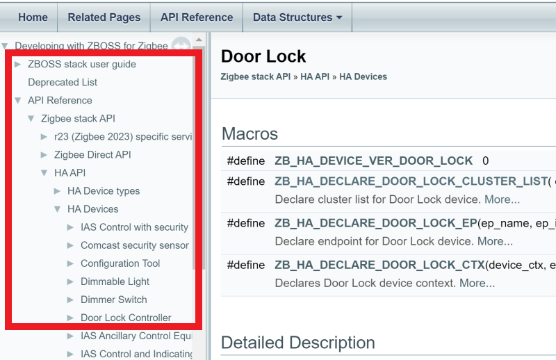
Door Lock API Documentation#
While at this documentation location, take time to review the other HA device types available, such as Door Lock Controllers, Shade & Shade Controllers, Window Covering & Window Covering Controllers, Thermostat, and the Temperature Sensor which we will be using later in the lab.
Task 3: Changing the project’s ZCL8 APIs#
Now it’s time to implement the code we need. Comparing the On Off Output and Door Lock documentation, it is clear that these two devices are very similar in regards to the clusters supported. Thus Identify, Basic, Scenes, and Groups cluster code remains unchanged
Replace on/off cluster attributes.
Door lock cluster attributes#// THIS CODE IS REMOVED /* On/Off cluster attributes */ //zb_uint8_t g_attr_on_off = ZB_ZCL_ON_OFF_ON_OFF_DEFAULT_VALUE; //#ifdef ZB_ENABLE_ZLL /* On/Off cluster attributes additions */ //zb_bool_t g_attr_global_scene_ctrl = ZB_TRUE; //zb_uint16_t g_attr_on_time = 0; //zb_uint16_t g_attr_off_wait_time = 0; //ZB_ZCL_DECLARE_ON_OFF_ATTRIB_LIST_EXT(on_off_attr_list, &g_attr_on_off, // &g_attr_global_scene_ctrl, &g_attr_on_time, &g_attr_off_wait_time); //#else //ZB_ZCL_DECLARE_ON_OFF_ATTRIB_LIST(on_off_attr_list, &g_attr_on_off); //#endif // THIS CODE REPLACES IT /* Door Lock cluster attributes data */ zb_uint8_t g_attr_door_lock_lock_state = 0; zb_uint8_t g_attr_door_lock_lock_type = 0; zb_bool_t g_attr_door_lock_actuator_enabled = ZB_FALSE; ZB_ZCL_DECLARE_DOOR_LOCK_ATTRIB_LIST(door_lock_attr_list, &g_attr_door_lock_lock_state, &g_attr_door_lock_lock_type, &g_attr_door_lock_actuator_enabled);
Replace device declarations.
Door lock device declaration#// THIS CODE IS REMOVED /********************* Declare device **************************/ /* Declare cluster list for the device */ //ZB_HA_DECLARE_ON_OFF_OUTPUT_CLUSTER_LIST(on_off_output_clusters, // on_off_attr_list, // basic_attr_list, // identify_attr_list, // groups_attr_list, // scenes_attr_list); /* Declare endpoint */ //ZB_HA_DECLARE_ON_OFF_OUTPUT_EP(on_off_output_ep, ZB_OUTPUT_ENDPOINT, on_off_output_clusters); /* Declare application's device context for single-endpoint device */ //ZB_HA_DECLARE_ON_OFF_OUTPUT_CTX(on_off_output_ctx, on_off_output_ep); // THIS CODE REPLACES IT /********************* Declare device **************************/ ZB_HA_DECLARE_DOOR_LOCK_CLUSTER_LIST(door_lock_clusters, door_lock_attr_list, basic_attr_list, identify_attr_list, groups_attr_list, scenes_attr_list); ZB_HA_DECLARE_DOOR_LOCK_EP(door_lock_ep, ZB_OUTPUT_ENDPOINT, door_lock_clusters); ZB_HA_DECLARE_DOOR_LOCK_CTX(device_ctx, door_lock_ep);
Replace the entire
test_device_interface_cbwith the following.Door lock device callback#void test_device_interface_cb(zb_uint8_t param) { zb_zcl_device_callback_param_t *device_cb_param = ZB_BUF_GET_PARAM(param, zb_zcl_device_callback_param_t); TRACE_MSG(TRACE_APP1, "> test_device_interface_cb param %hd id %hd", (FMT__H_H, param, device_cb_param->device_cb_id)); device_cb_param->status = RET_OK; switch (device_cb_param->device_cb_id) { case ZB_ZCL_SET_ATTR_VALUE_CB_ID: if (device_cb_param->cb_param.set_attr_value_param.cluster_id == ZB_ZCL_CLUSTER_ID_ON_OFF && device_cb_param->cb_param.set_attr_value_param.attr_id == ZB_ZCL_ATTR_ON_OFF_ON_OFF_ID) { if (device_cb_param->cb_param.set_attr_value_param.values.data8) { TRACE_MSG(TRACE_APP1, "set ON", (FMT__0)); #ifdef ZB_USE_BUTTONS //zb_osif_led_on(0); #endif } else { TRACE_MSG(TRACE_APP1, "set OFF", (FMT__0)); #ifdef ZB_USE_BUTTONS //zb_osif_led_off(0); #endif } } break; case ZB_ZCL_DOOR_LOCK_LOCK_DOOR_CB_ID: { zb_uint8_t lock_state = ZB_ZCL_ATTR_DOOR_LOCK_LOCK_STATE_LOCKED; TRACE_MSG(TRACE_APP1, "Lock the door", (FMT__0)); ZVUNUSED(zb_zcl_set_attr_val(ZB_OUTPUT_ENDPOINT, ZB_ZCL_CLUSTER_ID_DOOR_LOCK, ZB_ZCL_CLUSTER_SERVER_ROLE, ZB_ZCL_ATTR_DOOR_LOCK_LOCK_STATE_ID, &lock_state, ZB_FALSE)); zb_osif_led_on(0); } break; case ZB_ZCL_DOOR_LOCK_UNLOCK_DOOR_CB_ID: { zb_uint8_t lock_state = ZB_ZCL_ATTR_DOOR_LOCK_LOCK_STATE_UNLOCKED; TRACE_MSG(TRACE_APP1, "Unlock the door", (FMT__0)); ZVUNUSED(zb_zcl_set_attr_val(ZB_OUTPUT_ENDPOINT, ZB_ZCL_CLUSTER_ID_DOOR_LOCK, ZB_ZCL_CLUSTER_SERVER_ROLE, ZB_ZCL_ATTR_DOOR_LOCK_LOCK_STATE_ID, &lock_state, ZB_FALSE)); zb_osif_led_off(0); } break; default: device_cb_param->status = RET_OK; break; } TRACE_MSG(TRACE_APP1, "< test_device_interface_cb %hd", (FMT__H, device_cb_param->status)); }
This completes the necessary changes to make a Zigbee door lock device. You may
also with to replace ZB_INIT("on_off_light"); with ZB_INIT("door_lock");
for aesthetic appeal, however this is functionally insignificant.
Note
The existing ZB_OUTPUT_ENDPOINT (default value: 5) can be replaced with any
8-bit value that is not the Zigbee Device Object (ZDO) or Green Power (GP)
endpoints, 0 and 242 respectively.
Warning
If connecting to a Zigbee R22 Coordinator, you must also add
zboss_use_r22_behavior(); anywhere after ZB_INIT for compatibility.
Task 4: Testing the new device type#
After all changes have been made, build the project by going to
Project > Build Project. Then make sure you have a LaunchPad connected to your
PC and go to Run > Debug to flash the program on your LaunchPad. If you have
multiple LaunchPads connected to your PC, CCS may prompt you to select one of
the connected LaunchPads via the box below:

Select LaunchPad#
The selected LaunchPad’s serial number will be assigned to this project workspace so future program launches will automatically attempt to select this LaunchPad first if it is plugged in. More information about debugging with multiple probes can be found here.
As a Zigbee Router, the device will attempt to join a network any time the device is restarted, either through the RST button or a power cycle. If previously connected to a Zigbee network then it will attempt to find and rejoin this network using the settings saved in non-volatile flash memory.
During the Base Device Behavior (BDB) commissioning, the ZC can identify the device as a door lock through the Finding & Binding (F&B) process. This will allow it to either change or read the door lock state. On the LaunchPad, the lock state is indicated by the Green LED. The LED on means the lock is active, and off represents an unlocked device.

Ubiqua door lock capture#
Note
This was tested using a mass-market Zigbee Home Automation Gateway acting as the ZC to commission and communicate with the door lock device. It is possible to build your own Door Lock Controller CC2340 ZC application within the SimpleLink F3 SDK by using the instructions from the ZBOSS ZCL8 documentation.
Task 5: Bonus functional device#
The above tasks have helped demonstrate door lock device setup, but without connecting to and controlling an actual door lock. In this task we will further expand on this concept by creating a basic functional temperature sensor utilizing the hardware on the CC2340 device.
Project setup#
We will start with a new onoff_light project import and repeat Steps 1
through 3 of this lab, but with temperature_sensor nomenclature and referring
to Temperature Sensor documentation instead of the Door Lock counterpart.
Note in this instance it would make sense to set the Device Type in SysConfig
to Zigbee End Device with a suitable poll period set in the Power Management
tab, as a temperature sensor is typically battery-powered instead of being
mains-powered. Build the project to confirm there are no errors before continuing.
Application loop#
The default project assumes no application activity outside of the Zigbee device callback. In this instance, this is fine as the we will only be servicing a timer callback to check the value of the internal temperature sensor and do not need to iterate outside of this functionality. If instead you would like to occasionally service other operations, an application loop will need to be formed.
In
MAIN, replacezboss_main_loopwithmy_main_loopCreate a new
my_main_loopfunction aboveMAINApplication loop#void my_main_loop() { while (1) { /* ... User code ... */ zboss_main_loop_iteration(); /* ... User code ... */ } }
Create the functionality you need to achieve within the while loop
This is also demonstrated in the on_off_switch example
Using the Temperature TI Driver#
There is a Temperature TI Driver available to access the CC2340 internal
temperature sensor. As the Temperature module is already enabled in SysConfig,
all that needs to be done thus far is initializing it within the application.
Add
#include <ti/drivers/Temperature.h>to thetemperature_sensor.cheader includes.Add
Temperature_init();inside ofMAIN.
Documentation is available for more information about TI Drivers and their usage (see the TI Drivers Runtime APIs).
Timer creation and callback#
We will use the ClockP Driver Porting Layer (DPL) to create a periodic timer that will check the temperature sensor and update the temperature measurement attribute accordingly.
Add
#include <ti/drivers/dpl/ClockP.h>to thetemperature_sensor.cheader includes.Add
TEMP_TIMEOUTto the definitions, determine a value for a suitable periodic temperature sensor update (in units of us, thus 60000000 would be every one minute).Add initialization code in
MAIN.Application loop#ClockP_Params clockParams; ClockP_Handle tempClockHandle; ClockP_Params_init(&clockParams); clockParams.period = TEMP_TIMEOUT / ClockP_getSystemTickPeriod(); clockParams.startFlag = true; clockParams.arg = 0xAA; tempClockHandle = ClockP_create(tempTimeoutHandler, TEMP_TIMEOUT / ClockP_getSystemTickPeriod(), &clockParams);
Create the
tempTimeoutHandlerto update the temperature measurement whenever the timer expires.Timer callback#void tempTimeoutHandler (uintptr_t arg) { g_attr_temp_measurement_value = Temperature_getTemperature()*100; }
Now the project changes are complete. The application can be built and loaded onto the CC2340 device. Similar to before, the device will attempt to join a network any time the device is restarted either through the RST button or a power cycle. No BTN-x pushbutton activity is required and the LEDs will not turn on with this functionality.

Ubiqua temperature sensor capture#
Note
As before, this was tested using a mass-market Zigbee Home Automation Gateway. Likewise it would be possible to create a Thermostat CC2340 ZC device.