SimpleLink Low Power F3 SDK Environment Setup Guide#
Texas Instruments
10 min read
Introduction#
The following guide will walk you through how to setup the environment on the CC2340RX. This could take up to two hours to complete, make sure to pay attention to all of the required hardware and software to complete your setup.
Note
This is a setup process for Windows 10 machines and is similar on other operating systems.
Required hardware#
The following is needed to complete the setup.
Note
Other labs may need 2 devices, so you may want to source a second CC2340R5 LaunchPad™ and XDS110ET. This lab will only require one (1) of each of the following devices.
(1) SimpleLink™ XDS110ET LaunchPad™ development kit debugger with EnergyTrace™.
Should include a USB-C to USB-A cable for connecting the XDS110ET to a computer.
(1) Android or Apple smartphone that can access the Google or Apple app store, download, and run Texas Instruments’ SimpleLink Connect App found here.
Note
Here are links to the TI SimpleLink Connect app. Go to these on your phone and download and install the apps.
Or, here is the QR code to download the app:

A more detailed guide walking through this application is found in the module TI SimpleLink Connect App
Agenda#
1. Download and setup required software
2. Recommended steps for BTool
3. Loading a CC2340R5 project to CCS.
4. Configure a Serial Terminal
Download and Install Required Software#
Note: The following links will bring you to the product download page which includes all software versions.
SIMPLELINK-LOWPOWER-F3-SDK Software Development Kit (SDK)
Code Composer Studio CCS / CCS Cloud or IAR
See Dependencies section of SDK release notes for required version.
-
See Dependencies section of SDK release notes for required version.
-
See Dependencies section of SDK release notes for required version.
We recommend installing the SDK in the default directory
C:\ti
Using a custom install directory is possible, but it is recommended to make note of it for referencing in the future.
[Download SimpleLink™ Low Power F3 SDK v7.40 or newer].
Recommended Steps for Setup Verification and Ease of Use#
A. Make Shortcut to BTool#
We are going to make a shortcut to the Btool software. This shortcut may be used in subsequent labs for easy access.
Right-click in the desired location for the shortcut. We use the desktop here, but we suggest using a place that can be easily accessed later on.
Go to
Newat the bottom of the list, then clickShortcut.Paste
{SDK_INSTALL_DIR}\tools\ble5stack\btool\btool.exeinto the textbox
Type the location of the item:. This could look like this (using SDK 8.10.00.55):C:\ti\simplelink_lowpower_f3_sdk_8_10_00_55\tools\ble5stack\btool\btool.exe
Click on the
Nextbutton.Name the shortcut (The default name ‘BTool’ is recommended) and press the
Finishbutton.
B. Load Software with CCS#
After all the above steps have completed, we will run through the steps to loading an example and flashing it onto the device.
Open CCS and create your workspace.
Launch Code Composer Studio.
After opening CCS, you should be automatically placed in the workspace as seen in picture below. To change your current workspace, go to the “File” pop up menu located at the top left corner and select “Open Folder” to select a different folder to act as the workspace.
Note
Ensure no spaces are included in your workspace name.
Load a project into your workspace.
Here we are importing only the
basic_ble_LP_EM_CC2340R5_freertos_ticlangproject, as only a single project is required to complete the lab. If you would like to eliminate the need to continue importing projects in subsequent labs, you could import all projects in this step. For completing this lab, only thebasic_ble_LP_EM_CC2340R5_freertos_ticlangis needed.To import a project, at the top-left of the CCS window do the following, in order:
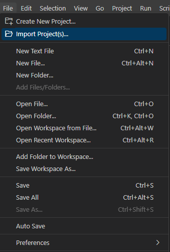
Left-click
Filethen clickImport Project(s)as shown below.
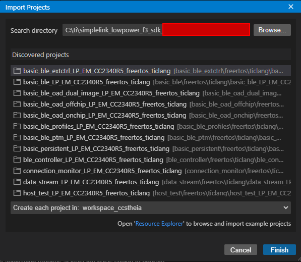
Import Project Example#
Left-click the
Browse...button.Navigate to the SDK directory
{SDK_INSTALL_DIR}.Go to
examples, thenrtos, thenLP_EM_CC2340R5, thenble5stack.Press the Enter key.
Select
basic_ble_LP_EM_CC2340R5_freertos_ticlang.Left-click the Finish button at the bottom right.
Import CCS Projects View#
Use a USB-C to USB-A cable to connect your board to any USB port on your computer. The LP-EM-CC2340R5 board should be connected to the LP-XDS110 (or LP-XDS110ET) first and then the USB-C to USB-A cable connects to the LP-XDS110.
Note
The green LED (on the XDS) should turn on when the device is connected.
Find the device’s COM port. This is used with Serial Monitor and BTool which are software tools used to communicate with the device. Serial Monitor allows the user to read messages being sent by the chip out through the UART communication interface. BTool enables user-device communication and controllability.
Press the Windows key and search for Device Manager, then press enter.
Open up the
Ports (COM & LPT)drop-down and you will see two ports that correspond to the device similar to what is shown below. The image below shows our device on COM21 and COM20. The COM21 port is what we will use to connect to the device using Serial Terminal. The serial port connection is always the one titled XDS110 Class Application/User UART.
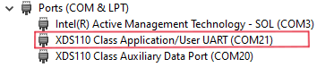
COM ports are unique to each board and computer combination. This means that a given board will likely be assigned different COM ports when plugged in to different computers.
Build and run the software on the device.
Left click on the project
basic_ble_LP_EM_CC2340R5_freertos_ticlangon the left side of CCS in the Explorer window pane.Left click Project then click on
Build Projectshown in the below image and wait for the project to finish building.
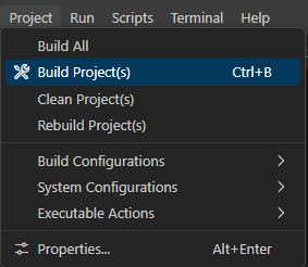
Build Icon#
Left click Run then click on
Debug Projectshown in the image below and wait for the program to finish flashing.
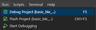
Debug Icon#
The debug button will build the project if needed, place the device into debug mode, flash the device, and start running the image in debug mode. When debugging, by default, after the device is flashed, it will reset and pause execution.
Left click the play button seen in the debug menu example below.
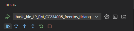
Debug Icon#
Note
Later on we will discuss how to make the software load to a specific device. This is useful for ensuring a specific program is flashed to a specific device when multiple devices and projects are to be used simultaneously
Visually inspect the board and see the green and red LEDs are turned on. The XDS110ET will have flashing green and red LEDs when the software is loading.
Note
Do not close any software or unplug the device yet. We will now verify and setup Serial Terminal which will be commonly used in the future labs.
Setup the serial terminal to see the device’s UART output.
C. Configure Serial Terminal standard connection options#
Here we will walk through using a serial terminal. In this example, PuTTY will be used.
The Serial Terminal can be used to receive and send UART data to your evaluation board through the USB serial interface.
To use the terminal, open PuTTY and make sure the following parameters are configured:
For ‘Connection Type’ select
SerialSerial Line: Your device’s UART COM Port (COM1 in this guide, but yours will be different.)
Speed:
115200
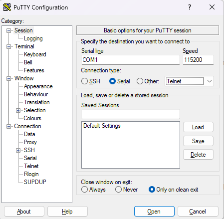
PuTTY connection parameters for connecting to a CC23xx device#
Here is what the terminal should now be showing after successfully
flashing and running Basic BLE:
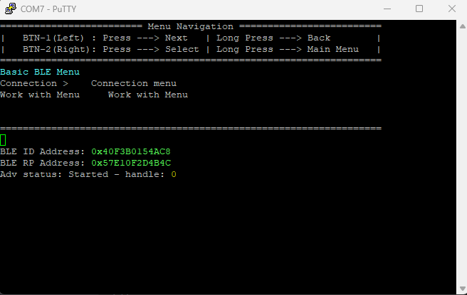
PuTTY Terminal with Basic BLE Flashed#
Conclusion#
You have now fully setup your development envinroment and can either take a break or immediately begin SimpleLink basic_ble example.
Material for additional information#
The following documentation provides more in-depth information that can be useful for debugging and development with the CC23XX series of devices. These are not required for completing the setup or following lab(s) and are posted here at the beginning for easy access when referring to this startup guide.