Coexistence
The coexistence (coex) feature is a means to organize wireless packet traffic for communication protocols operating in the same frequency band. Instead of interfering with each other’s transmissions, affecting the RF performance, two co-located devices will have a dedicated communication interface to signal and determine access to the shared frequency band.
The coex feature is not a standard, but is rooted in the recommendations provided by IEEE 802.15.2: “Coexistence of Wireless Personal Area Networks with Other Unlicensed Frequency Bands Operating Wireless Devices”. The industry approach is more of a “best-practice” when it comes to this feature, and every device supporting a coexistence interface is free to implement its own solution to the problem.
The coex interface implemented for SimpleLink CC13x2/CC26x2 devices is compatible with Wi-Fi devices that support Packet Traffic Arbitration (PTA). This is one of the approaches recommended and described by IEEE 802.15.2. This approach is based on a shared PTA control module between the coexisting devices, to decide which device is permitted to communicate in the shared frequency band. Many Wi-Fi devices implement their version of such a module, and the implemented coex feature is based on the assumption that the PTA control module is embedded in the Wi-Fi device. The Wi-Fi device will therefore have a master role in this coex device scheme, as it controls the PTA logic. The coexistence interface can be abstracted to a signal interface between the two devices, as illustrated in the figure below. For an example of supported Wi-Fi devices, see SimpleLink CC3235SF, and see SimpleLink WLAN Access Point application note for an example of coexistence solutions.
Packet Traffic Arbitration (PTA) Interface
The PTA interface between the two devices is a set of wired signals. What information to communicate, and ultimately the number of signals used, will depend on the implementation of the PTA control module. Based on the most common Wi-Fi PTA implementations, the implemented coex feature supports three sets of signals. These sets of signals, or coex modes, are named:
- 3-Wire
- 1-Wire REQUEST
- 1-Wire GRANT
From the naming scheme, it is obvious that the supported coex modes use at max three wires to signal state information to the Wi-Fi device. However, the two 1-Wire modes can be seen as subsets of the signaling provided by 3-Wire mode. As illustrated in the table below, the 3-Wire mode utilizes all the provided signals, and for both 1-Wire REQUEST and 1-Wire GRANT two of the signals are disabled.
| PTA Coex Signals | |||
|---|---|---|---|
| Coex Mode | REQUEST | PRIORITY | GRANT |
| 3-Wire | X | X | X |
| 1-Wire REQUEST | X | ||
| 1-Wire GRANT | X | ||
Furthermore, the supported coex modes can be illustrated as in the block-diagrams in the figures below. Seen from the BLE device, the REQUEST and PRIORITY signals are defined as outputs, and the GRANT signal is defined as an input.
All coexistence modes are not supported on all Wi-Fi devices. The SimpleLink CC3135 and CC3235 Wi-Fi devices only support the 1-Wire REQUEST mode.
Coexistence Signaling
The coexistence signaling approach for the 3-Wire mode, using the three available signals, can be summarized in two steps:
- Coex slave (BLE device) requests permission to perform RF activity, with info on:
- Priority of the request (low/high)
- Type of RF activity (TX/RX)
- Coex master (Wi-Fi device) will grant or deny the request
From the coex slave perspective, the above two steps are implemented by configuration of the following signals for the PTA interface:
Coex REQUEST signal:
This is an output signal, controlled by the coex slave. This signal is used to indicate a request to use the shared frequency band, that is, perform any RF activity.
Coex PRIORITY signal:
This is an output signal, controlled by the coex slave. This signal is time-shared between first indicating the priority of the access request, followed by indicating the type of RF activity (TX/RX) the device will perform. At first, when the REQUEST signal is asserted, the value of the PRIORITY signal will indicate the priority (low/high) of the request. After a defined 20 µs, the PRIORITY signal is used to indicate the type of RF activity. This means that the signal will be de-asserted or asserted depending on if the scheduled activity is RX or TX.
Coex GRANT signal:
This is an input signal, controlled by the coex master. This signal indicates the response of the PTA decision, that is, whether the request is granted or not.
Note
The terms signal assert and signal de-assert are used to describe the value change of a signal to respectively active and idle. For an active high signal, the signal is asserted by changing the signal value from low to high. For an active low signal, the signal is asserted by changing the signal value from high to low. For the opposite signal operation, de-assert, the signal value changes from active to idle.
| Active Level | Idle Level | Assert | De-assert |
|---|---|---|---|
| High | Low | Low → High | High → Low |
| Low | High | High → Low | Low → High |
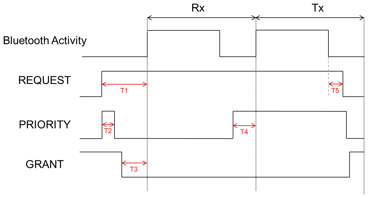
In order to support time-shared signals, the coex feature is heavily dependent on accurate timing. What makes this implementation compatible with a Wi-Fi device that supports a PTA interface, is the adherence to such timing requirements. The figure below illustrates a timing diagram for a BLE device signaling the scheduled RF activities, receive and transmit respectively. Note that the diagram depicts REQUEST and PRIORITY signals as active high, but the GRANT signal is by default defined as active low. This means that a coex request is granted when the GRANT signal is driven low by the Wi-Fi device.
The sections marked with red in the diagram, T1 - T5, are intended to highlight the following signaling and timing requirements to be aware of:
- T1: The REQUEST signal is asserted by the coex slave, and indicates to the coex master that the coex slave will perform RF activity. This is a request for access to the shared frequency band. In the timing diagram, this happens at a time T1 before the BLE RX command is scheduled to run. T1 can be expected to be in the range of 90-150 µs.
- T2: The PRIORITY signal is time-shared between indicating priority and and type of RF activity (TX/RX) the BLE device will do. The time T2 indicates the duration of which the PRIORITY signal indicates priority; from the time the REQUEST signal is asserted, and for a duration of 20 µs. For the rest of the request interaction, as long as the REQUEST signal is asserted, the PRIORITY signal indicates TX/RX activity.
- T3: In a period before the scheduled RF activity, the coex master will assert or de-assert the GRANT signal. This is to indicate if the request from the coex slave, asserted at T1, is granted or not. At period T3, 50-135 µs, the GRANT signal is expected to be in a stable state. The coex slave will read the GRANT signal within the T3 period, and use this value as the answer to the request.
- T4: The PRIORITY signal is time-shared, as explained under T2. After T2, the PRIORITY signal indicates the type of RF activity (and no longer priority). In the timing diagram, the coex slave asserts the PRIORITY signal at T4 before it transmits, to indicate the change in type of activity; from RX to TX. The RX activity is indicated by de-asserting the PRIORITY signal, and the TX activity is indicated by asserting the PRIORITY signal.
- T5: After the coex slave is finished with the scheduled RF activities, it will de-assert the REQUEST signal. This is how the coex slave indicates to the coex master that the requested RF activity is finished. This will happen 0-25 µs after the last RF activity.
Configuration Options
The coex configuration options are made available from the RF driver module in SysConfig.
Depending on the application, use case, and what Wi-Fi device the SimpleLink CC13x2/CC26x2 BLE device is intended to coexist with, certain options are up to the user to configure.
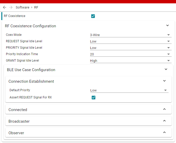
Coex mode: As described in Packet Traffic Arbitration (PTA) Interface, the coex feature can be configured to interface with PTA controllers based on 3-Wire, 1-Wire REQUEST or 1-Wire GRANT, which are different combinations of enabling or disabling the supported coex signals.
Coex signal idle level: The signal idle level can be configured as low or high, which in other terms means that the same signal is either respectively active high or active low. To configure the active levels used in Coex 3-Wire timing diagram, both REQUEST and PRIORITY are set to idle level low, and GRANT is set to idle level high.
Priority indication time: As described in Coexistence Signaling, the PRIORITY signal is time-shared between indicating priority and the type of RF activity. The Priority Indication Time field in SysConfig specifies how long, in microseconds, the PRIORITY signal indicates priority before it switches to indicate the type of RF activity.
BLE Use Case Configuration: Separate configuration can be set for different BLE use cases (connection establishment, connected, broadcaster, observer) if the application requires the behavior to differ between these. The following configuration options can be set for each of these use cases separately:
- Default priority: This is the default behavior of the PRIORITY signal when it indicates the priority of the coex request. It can be set to either low or high.
- Assert REQUEST signal for RX: This option is by default enabled. However, depending on the use case and application, the coex behavior can be configured to not assert REQUEST for any scheduled RX activities. In this case, the BLE device does not care if the Wi-Fi device is performing any RF activities of its own. With reference to Coex 3-Wire timing diagram, disabling this option would shift the assertion of the REQUEST signal to the right. The REQUEST signal will then be asserted at a time T1 before the TX activity instead of the RX activity. This means that both REQUEST and PRIORITY signals will stay idle for the RX activity.
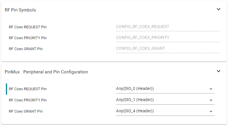
Coex pin mapping: Depending on the mode, the coex signal(s) used for the PTA interface with the Wi-Fi device can be mapped to any available DIO pins. This is configured in the pin mux section of the RF module, as illustrated in the figure below.


