Application Layer
Since the micro stack can support multiple functionalities (broadcaster, observer, connection monitor), it is up to the application layer to define the behavior of the system. The following sections will discuss the TI provided implementations of monitor role.
micro_ble_cm.c: rtls_passive application
Connection Monitor (CM) Application
The connection monitor application is built on top of the uGAP layer operating in monitor mode and is responsible for implementing the high level connection tracking feature. This includes:
- Initializing connection parameters for a connection to monitor
- Performing the initial scan to find a connection event
- Scheduling subsequent scans to continue following the connection
The following sections will describe the above list in detail.
Initializing CM Session
In order to follow a connection, the CM needs to know the connection parameters that were exchanged during the connection process between Central and Peripheral. These include:
- access address
- connection interval
- hop value
- next channel
- channel map
- CRC initialization value
These parameters can be obtained from a BLE5-Stack application by calling
the HCI_EXT_GetActiveConnInfoCmd command. Once they are obtained,
they should be shared (via an out of band mechanism such as UART, LIN, CAN etc)
with the CM device. The CM device then can use ubCM_startExt() to start the
initial scan.
Starting a Monitor Session
In order to start tracking a connection the connection monitor needs to perform an initial scan with long scan duration in order to catch a connection event. This scan should be at worst case the connection interval times the number of active channels in order to ensure the connection can be detected.
The logic trace below shows the initial scan of connection monitor and it was generated by enabling the RF observable pins on Central and Peripheral device in the connection (RX, TX) as well as the connection monitor (RX). For more information regarding RF observable, please refer to Debugging RF Output

Note
For example, if the active channel map is channel 0, 1, 2, 3, 4, 5 and the hop number is 1. The next channel sent from peripheral is 2 and connection interval is 7.5 ms. Then CM will stay at channel 2 for maximum 45 ms(6 * 7.5).
Monitoring a Connection
Once a packet is received during the initial scan the CM will setup smaller scans based on the next expected event. Since it is now monitoring the connection, it can calculate the channel and instant (adjusted for Central and Peripheral sleep clock accuracy) to listen for the next event.
The core of connection monitoring is based on
monitor_indicationCB: Invoked when a packet is receivedmonitor_completeCB: Invoked when a scan window has completed.The logic trace below shows the CM actively tracking a connection

The sequence diagram below illustrates the whole process of how CM starts monitoring the connection and report RSSI to application.
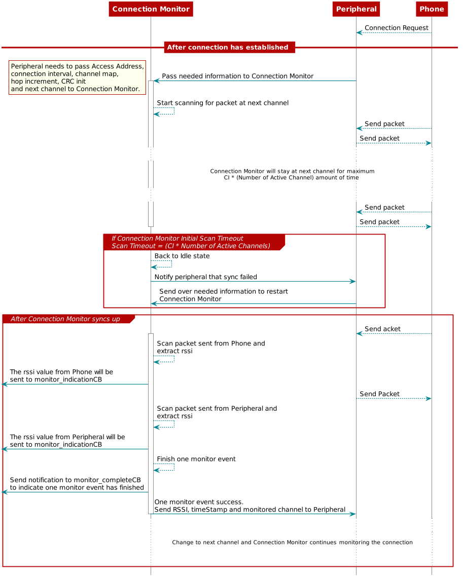
Figure 156. Connection Monitor initialization and connection tracking
Lose Sync
Application layer can decide how many consecutive connection events
CM is allowed to miss by setting BLE_CONSECUTIVE_MISSED_CONN_EVT_THRES.
CM keeps track of consecutive missed events(consecutiveTimesMissed)
and total missed events(timesMissed).
Those variables can be found under ubCM_ConnInfo_t struct.
1 2 3 4 5 6 7 8 9 10 11 12 13 14 15 16 17 18 19 20 21 22 23 24 25 26 | typedef struct
{
uint8_t sessionId; //! Number 1-255 assigned as they are created identifying each connection monitor session
uint8_t timesScanned; //! track count of recent events monitored to determine next priority CM session to avoid starvation
uint8_t timesMissed; //! missed count of recent events monitored
uint8_t consecutiveTimesMissed; //! consecutive missed count of recent events monitored
uint32_t accessAddr; //! return error code if failed to get conn info
uint16_t connInterval; //! connection interval time, range 12 to 6400 in 625us increments (7.5ms to 4s)
uint16_t scanDuration; //! Required scan window to capture minimum of 1 packet from Master and Slave up to max possible packet size
uint8_t hopValue; //! Hop value for conn alg 1, integer range (5,16)
uint16_t combSCA; //! mSCA + cmSCA
uint8_t currentChan; //! current unmapped data channel
uint8_t nextChan; //! next data channel
uint8_t chanMap[CM_NUM_BYTES_FOR_CHAN_MAP]; //! bitmap of used channels, use to reconstruct chanTableMap
uint8_t masterAddress[CM_DEVICE_ADDR_LEN]; //! BLE address of connection master
uint8_t slaveAddress[CM_DEVICE_ADDR_LEN]; //! BLE address of connection slave
uint8_t rssiMaster; //! last Rssi value master
uint8_t rssiSlave; //! last Rssi value slave
uint32_t timeStampMaster; //! last timeStamp master
uint32_t timeStampSlave; //! last timeStamp slave
uint32_t currentStartTime; //! Current anchor point
uint32_t nextStartTime; //! Record next planned scan anchor point to compare with competing CM sessions
uint32_t timerDrift; //! Clock timer drift
uint32_t crcInit; //! crcInit value for this connection
uint16_t hostConnHandle; //! keep connHandle from host requests
} ubCM_ConnInfo_t;
|
Once consecutiveTimesMissed is larger than BLE_CONSECUTIVE_MISSED_CONN_EVT_THRES,
the CM will terminate the monitor session and notify the
host. Host can then restart the monitor session by going
through Initializing CM Session, Starting a Monitor Session
and Monitoring a Connection.
The sequence diagram below illustrates the whole process of how CM deal with losing sync.
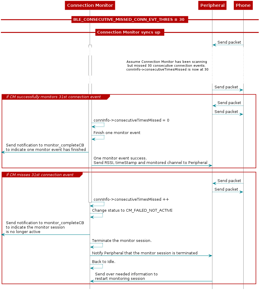
Figure 157. Connection Monitor loses sync
Connection Information Update
CM does not extract the payload information, it only measures the RSSI from the payload. Therefore, if there are control packets such as channelmap update, connection parameters update exchanged between central and peripheral, the device that has wired connection to CM needs to pass on the information so that CM can continue monitoring the connection.
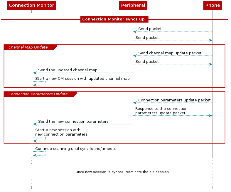
Figure 158. Connection Monitor control packets update
Monitor Multiple Connections
CM can monitor multiple connections even when all the monitored connections have different connection intervals.
To determine which connection to monitor, after ending each monitor session, the CM scheduler will sort the all connections based on future start time. Then CM will do a timing conflict check on selected and sec connections. If (conn1 start time + monitor/scan duration) > conne2 start time, then CM will consider there is conflict between connection 1 and connection 2.
The monitor/scan duration for each monitor session is determined by the following parameters:
Sleep Clock Accuracy(SCA)for both central and peripheral device.
The processing time for the radio core and the CM software.
Time needed to receive only one packet per central and periperal device using 1M Phy. No MD in the same connection event.
Note
CM example is to extract (RSSI) information for central and peripheral device when they are in connection. It does not extract payload information, therefore, there is no need to monitor more packets.
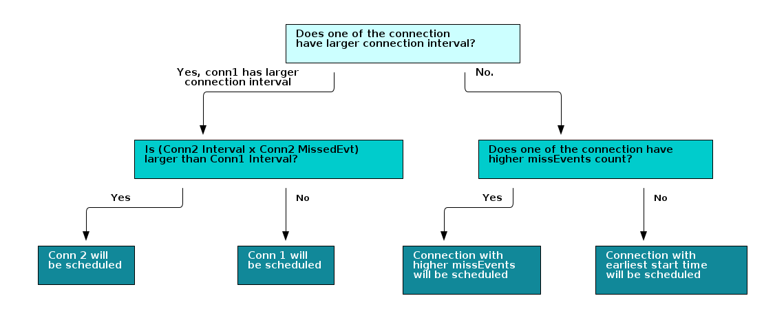
When there is timing conflict among monitored connections, CM will decide which connection to monitor based on the following factors and the list below is in order of priorities from high to low:
If one of the connection has larger connection interval, then the connection which CM misses more monitored time will be scheduled.
Note
For example, if the next connection events for connection 1(CI = 100ms) and connection 2(CI = 40ms, cmMissedEvent = 3) are in conflict, then CM will monitor connection 2 because connection 2 missed more monitored time (100 < 40*3).
Connection with higher cmMissedEvents.
Connection with earlier start time.
The following diagram illustrates how the CM handling monitor session conflict:
Limitation
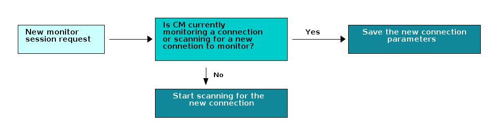
When requesting a new monitor session while CM has already been monitoring connection(s), the CM will process the request based on the timing of when the request comes in.
- If the request comes in when CM is not monitoring a connection, the request will be processed right away. This means that CM will start scanning for a new connection immediately after receiving the request.
- If the request comes in when CM is monitoring a connection, the information of the new connection will be saved and processed once the current monitor session has ended.
The following diagram illustrates how the CM handles new monitor request.
Due to the nature of how Starting a Monitor Session works, the radio core might still be scanning for the new connection when it is time to monitor existing connection(s). CM will prioritize scanning for new connection over monitoring existing connection(s). Once CM is able to track the new connection or scan timeout, it will continue monitoring the existing connections.
That being said, if there are multiple new monitor sessions’ requests coming in, then CM will process all the new monitor sessions’ requests before it goes back to monitor the existing connections.
In addition to the above limitation, CM example also has the following constraints:
- Connections must use LE Channel Selection Algorithm #1
- Connections must use LE 1M PHY
- Connections must exist on LE Data channels