Application Overview
TI 15.4-Stack example applications are designed to enable faster end-product development by providing implementation of various common-protocol stack-specific tasks, and other essential features such as nonvolatile memory storage, saving information over power cycles, in addition to protocol functionality. This chapter explains the example application implementation to help developers quickly modify the TI 15.4-Stack out-of-box example applications for customized development. The following sections detail the example applications of the TI 15.4-Stack projects.
Pre-RTOS initialization
Application architecture: the Application task which is the lowest priority task in the system. The code for this task resides in the
ApplicationIDE folder.OSALPort: an interface module between TI 15.4-Stack services (such as TI 15.4-Stack APIs) as well as certain primitive services (such as thread synchronization) provided by the real-time operating system (RTOS)
Application Architecture
Figure 22. shows the block diagram of the Sensor and Collector example applications. Refer to the TI 15.4-Stack Linux User’s Guide for details on the Linux example applications on an external host MCU.
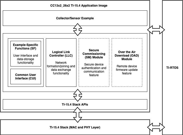
Figure 22. Example Application Block Diagram
High-level descriptions of various blocks in Figure 22. follow:
Example Application: The platform-independent implementation of the example use case. The TI 15.4-Stack out-of-box demonstrates two use cases – Collector and Sensor. Developers can modify the code in this module in out-of-box example applications for custom application requirements, to quickly develop end products. This is platform-independent code, used as in the Linux example application and also the SimpleLink MCU platform example applications.
Logical Link Controller: Implements various essential IEEE 802.15.4 specific or Wi-SUN (for frequency-hopping configuration) specific tasks, such as network formation, network joining, and rejoining. This block intends to offload various protocol-specific implementations from the developers, and enable faster custom application development. This is platform-independent code used in the Linux example application and SimpleLink MCU platform example applications.
TI-RTOS Start-up Code: Initializes the application (see Start-Up in main() for more details).
Utility Functions: Provides various platform utilities which the application can use for example LCD, timers, keys, and so on.
Application-Specific Functions: Implements platform-specific functions such as data storage over power cycles (non-volatile memory), and provides user interface functions such as handling button presses or displaying essential information on the LCD, and so on.
TI 15.4-Stack API Module (API MAC Module): This module provides an interface to the management and data services of the 802.15.4 stack through the OSALPort Framework module. This is further described in OSALPort Framework.
Application File Structure
Figure 23. shows the basic application source tree of the Sensor and Collector example applications. Refer to the TI 15.4-Stack Linux User’s Guide for details on the Linux example applications on an external host MCU.
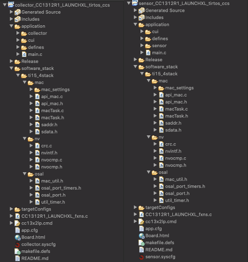
Figure 23. Example Application Source Tree
High-level descriptions of various folders in Figure 23. follow:
Application: Includes all files associated with the application layer of a TI 15.4-Stack based example; in the image above we show the basic sensor/collector examples, on these examples the application layer is composed of:
Sensor/Collector:
collector/sensor.[c/h]: The TI 15.4-Stack out-of-box examples demonstrates two use cases – Collector and Sensor. These source files contain the “main” loop of the application, some of the functions and values that these source files handle and control are:
handling periodic events such as: reading sensors, sending poll messages, sending broadcast messages, etc.
handling incoming messages
sending sensor data messages
store data structures such as: event states, timeout values, and statistics
Developers can modify the code in these files to match their custom application requirements and quickly develop end products. For a more in depth description on these, please refer to the READMES in the imported projects.
csf/ssf.[c/h]: These files, which stand for collector/sensor specific functions, provides various platform utilities that the application can use for example LCD, timers, keys, and so on.
smsgs.h: Contains all data structures for messages sent over the air.
link_controller: Implements various essential IEEE 802.15.4 specific or Wi-SUN (for frequency-hopping configuration) specific tasks, such as network formation, network joining, and rejoining. This block intends to offload various protocol-specific implementations from the developers, and enable faster custom application development. Some of the responsabilities of these sources are to handle responses received from the MAC by using callback functions to trigger different events and also populating key structures that can be used by the higher level application layer.
CUI: Has all the source code that controls the serial console user interface, for more information on this module you can refer to Common User Interface.
defines: Contains all the pre-defined symbols for the project. Here you can modify some stack parameters such as AUTO_START, NV_RESTORE, Sensor Type, etc…
Main.c: This file will handle any asserts, the main task functions to start up the application, and functions that read memory addresses. Also responsible for setting up NV drivers, initializing the collector application, initializing CUI, and kick starting the main task function called appTaskFxn which will trigger the respective application to begin. Also includes user defined assert handler functions for various asserts. (see Start-Up in main() for more details).
Release: This folder will be empty by default, but will get filled by all of the compiler’s output files once you trigger the first build of the project. Here you will also find the output binaries that you can use to flash onto devices using SmartRF Flash Programmer or Uniflash .
Software_stack:
MAC: Contains the user accessible APIs and task that runs all API requests done by the application. Here you will find mac specific settings such lower and upper bounds for some parameters, and allocation sizes for message queues.
NV: The NV area of flash is used for storing persistent data for the application. TI 15.4-Stack uses the NV On-Chip Multi-Page (NVOCMP) driver to maintain this memory area.
OSAL: provides an interface to the management and data services of the 802.15.4 stack through the OSALPort Framework module. This is further described in OSALPort Framework.
sensor/collector[.syscfg]: (Only CC13xx/CC26xx) These configuration files take avantage of the System Configuration Tool (SysConfig) is a graphical interface for configuring your SimpleLink CC13xx/CC26xx SDK project. Configuration files, C source files and header files are generated based on the parameters configured in the SysConfig dashboard. If you want to learn more about SysConfig you can go to the SysConfig chapter.
Start-Up in main()
The main() function inside of main.c is the application starting point
at runtime. This point is where the board is brought up with interrupts disabled
and board-related components are initialized. Tasks in this function are
configured by initializing the necessary parameters, setting its priority, and
initializing the stack size for the application. In the final step, interrupts
are enabled and the SYS/BIOS kernel scheduler is started by calling
BIOS_start(), which does not return. See the CC13x2 CC26x2 SimpleLink Wireless MCU Technical Reference Manual for information on
the start-up sequence before main() is reached.
/*!
 * @brief       "main()" function - starting point
 */
int main(void)
{
    Task_Params taskParams;

#ifndef USE_DEFAULT_USER_CFG
    macUser0Cfg[0].pAssertFP = assertHandler;
#endif

    /*
     Initialization for board related stuff such as LEDs
     following TI-RTOS convention
     */
    Board_init();

#if defined(FEATURE_BLE_OAD) && !defined(OAD_IMG_A)
    /* If FEATURE_BLE_OAD is enabled, look for a left button
     *  press on reset. This indicates to revert to some
     *  factory image
     */
    if(!PIN_getInputValue(CONFIG_PIN_BTN1))
    {
        OAD_markSwitch();
    }
#endif /* FEATURE_BLE_OAD */

#if (defined(FEATURE_BLE_OAD) || defined(FEATURE_NATIVE_OAD)) && !defined(OAD_ONCHIP)
    SPI_init();
#endif

#if !defined(POWER_MEAS) && !defined(CUI_DISABLE)
    /* Initialize CUI UART */
    CUI_params_t cuiParams;
    CUI_paramsInit(&cuiParams);

    // One-time initialization of the CUI

    // All later CUI_* functions will be ignored if this isn't called
    CUI_init(&cuiParams);
#endif

#ifdef OSAL_PORT2TIRTOS
    _macTaskId = macTaskInit(macUser0Cfg);
#endif

    /* Configure task. */
    Task_Params_init(&taskParams);
    taskParams.stack = appTaskStack;
    taskParams.stackSize = APP_TASK_STACK_SIZE;
    taskParams.priority = APP_TASK_PRIORITY;
    Task_construct(&appTask, appTaskFxn, &taskParams, NULL);

#ifdef USE_ITM_DBG
    ITM_config itm_config =
    {
      48000000,
      ITM_6000000
    };
    ITM_initModule(itm_config);
    ITM_enableModule();
#endif /* USE_ITM_DBG */

    BIOS_start(); /* enable interrupts and start SYS/BIOS */

    return (0);
}
OSALPort Framework
OSALPort is a module that provides a mechanism for the Application to interface with TI 15.4-Stack services (such as TI 15.4-Stack APIs), as well as certain primitive services (such as thread synchronization) provided by the real-time operating system (RTOS). OSALPort allows both the Application and protocol stack tasks to efficiently operate, communicate, and share resources in a unified RTOS environment.
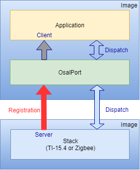
Figure 24. OSALPort Application – Protocol Stack Abstraction
OSALPort Protocol Stack Service
As depicted in Figure 24., the OSALPort core use case involves messages between a server entity (the TI 15.4-Stack task) and a client entity (the Application task). The reasoning for this architecture is twofold: to enable independent updating of the application and TI 15.4-Stack, and to maintain API consistency as the software is ported from legacy platforms (for example OSAL for the CC253x) to the CC13xx or CC26xx TI-RTOS. The OSALPort TI 15.4-Stack Service serves as the Application interface to all TI 15.4-Stack APIs. Internally, when a TI 15.4-Stack protocol stack API is called by the Application, the OSALPort module routes (dispatches) the command to the TI 15.4-Stack, and where appropriate, routes messages from the TI 15.4-Stack to the Application.
OSALPort Service
OSALPort includes a service that abstracts various operating system-related functions. Due to shared resources, and to maintain interprocess communication, the Application must use the following OSALPort service functions.
Messaging and Thread Synchronization
Heap Allocation and Management
Messaging and Thread Synchronization
The messaging and thread synchronization functions provided by the OSALPort let users design an application to protocol stack interface in the multithreaded RTOS environment. Within the OSALPort, messaging between two tasks is achieved by sending a message block from one thread to the other using a message queue. The sender allocates memory, writes the content of the message into the memory block, and then sends (enqueues) the memory block to the recipient. Notification of message delivery is accomplished using a signaling semaphore. The receiver wakes up on the semaphore, copies the message memory block (or blocks), processes the message, and returns (frees) the memory block to the heap.
The Stack uses the OSALPort for notifying and sending messages to the Application. These service messages (such as state change notifications) received by the Application task are delivered by the OSALPort and processed in the task context of the Application.
Heap Allocation and Management
The OSALPort provides the Application with global heap APIs for dynamic memory allocation. OSALPort uses this heap for all protocol stack messaging as well as to obtain memory for other OSALPort services. TI recommends that the Application uses these OSALPort APIs for dynamic memory allocation within the Application.
OSALPort Initialization and Registration
To instantiate and initialize the OSALPort service, the following functions
must be called by the application in main() before starting the SYS/BIOS
kernel scheduler.
static uint8_t _macTaskId;
_macTaskId = macTaskInit(macUser0Cfg);
Calling macTaskInit(macUser0Cfg) initializes the OSALPort service
(for example, heap manager) and framework. Calling Sensor_init(_macTaskId)
in appTaskFxn creates, but does not start, the TI 15.4-Stack protocol stack task.
Semaphores must be created to send and receive messages
through the OSALPort. This registration is done for the application in
zclSampleLight_initialization(), which is called by the application’s initialization
functions. The following is the call to the OSALPort in ApiMac_init()
in api_mac.c
Semaphore_Params semParam;

macTaskId = macTaskIdParam;

Semaphore_Params_init(&semParam);
semParam.mode = Semaphore_Mode_BINARY;
Semaphore_construct(&appSem, 0, &semParam);
appSemHandle = Semaphore_handle(&appSem);

appTaskId = OsalPort_registerTask(Task_self(), appSemHandle, &appEvents);
OsalPort_registerTask supplies the Task_self(), appSemHandle,
and appEvents inputs which then returns the appTaskId
subsequently used by the OSALPort to facilitate messages between the Application and server
tasks. The Task_self() argument points to the task destination message queue,
appSemHandle represents the semaphore used for signaling, and
appEvents points to the event flag. Each task registering with the OSALPort
has unique appSemHandle and appEvents identifiers.
Note
TI 15.4-Stack APIs defined in zstackapi.c, and other OSALPort services, are not available for use before OSALPort registration.
OSALPort Thread Synchronization
The OSALPort module switches between Application and Stack threads through
the use of semaphore synchronization services provided by the
RTOS. To allow a client or a server thread to block until it receives a
message, OSALPort uses Semaphore_pend(appSemHandle, BIOS_WAIT_FOREVER ).
This blocks until the semaphore associated with the caller RTOS thread is posted.
Allowing an application or a server thread to block yields the processor resource to other lower priority threads, or conserves energy by shutting down power and clock domains whenever possible. The semaphore associated with an RTOS thread is signaled by either of the following conditions.
A new message is queued to the Application RTOS thread queue.
Semaphore_post()is called for the semaphore.
Semaphore_post() is provided so that an application or a server can add
its own event to unblock Semaphore_pend() and synchronize the thread.
Semaphore_post() accepts a semaphore handle
appSemHandle as its sole argument. The semaphore handle
associated with the thread is registered through the OsalPort_registerTask() call.
Example OSALPort Usage
Figure 25. shows an example command being sent from
the application to the TI 15.4-Stack through the OSALPort, with a corresponding
return value passed back to the application. macTaskInit(macUser0Cfg) initializes
the OSALPort module instance itself and Sensor_init(_macTaskId)
creates a task per external image, with an entry function at a known address.
After initializing the OSALPort, the Application task registers with the
OSALPort using OsalPort_registerTask. After the SYS/BIOS
scheduler starts and the Application task runs, the application sends a protocol
command defined in cllc.c such as ApiMac_mlmeSetReqArray().
The protocol command is not executed in the application thread. Instead the
command is encapsulated in an OSALPort message and routed to the TI 15.4-Stack
task through the OSALPort. In other words, this command is sent to the
OSALPort where it is then executed on the TI 15.4-Stack. The Application thread meanwhile
blocks (waits for) the corresponding command status message (status). When the TI 15.4-Stack
protocol stack finishes executing the command, the command status message response is
sent through the OSALPort back to the application thread.
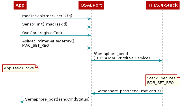
Figure 25. OSALPort Messaging Example
System Stack
Besides the RTOS heap previously mentioned, there are other sections of memory to consider. As described in TI-RTOS (RTOS Kernel) Overview, each task has its own runtime stack for context switching. Furthermore, another runtime stack is used by the RTOS for main(), HWIs, and SWIs. This system stack is allocated in the Application linker file, to be placed at the end of the RAM of the Application.
For CCS, the RTOS system stack is defined by the Program.stack parameter in the app.cfg RTOS configuration file.
 /* ================ Program configuration ================ */
 /*
 *  Program.stack can be set to 0 to allow the setting
 *  of the system stack size to be determined in the example's
 *  linker command file.
 */
if (!Program.build.target.$name.match(/iar/)) {
    Program.stack = 1376;

}
Then the RTOS system stack is placed by the linker in the RAM space of
the Application (<DEVICE>lp.cmd):
/* Create global constant that points to top of stack */
/* CCS: Change stack size under Project Properties */
__STACK_TOP = __stack + __STACK_SIZE;
General Application Architecture
This section describes how an Application task is structured in more detail. Having an understand of the out of box application architecture will allow develop custom applications quickly and easily with most software reuse from out of box example applications.
Application Initialization Function
Tasks describes how a task is constructed. After the
task is constructed and the SYS/BIOS kernel scheduler is started, the
function that was passed during task construction is run when the task is ready.
Power-management functions are initialized here and the OSALPort module is
initialized through Sensor_init(_macTaskId). The primary IEEE address (programmed by
TI) is obtained from the CCFG area of the flash memory and NV drivers
are initialized. The application task (Sensor application in
Figure 26.) is initialized and started.
/*!
 * @brief       Main task function
 *
 * @param       a0 -
 * @param       a1 -
 */
Void appTaskFxn(UArg a0, UArg a1)
{
    /* The following code encapsulated in TI_154STACK_FPGA flag is used for
     * internal FPGA evaluation of the 15.4 Stack and should not be used with
     * TI hardware platforms. */
#ifdef TI_154STACK_FPGA
    /* FPGA build disables POWER constraints */
    Power_setConstraint(PowerCC26XX_IDLE_PD_DISALLOW);
    Power_setConstraint(PowerCC26XX_SB_DISALLOW);

    IOCPortConfigureSet(IOID_4, IOC_PORT_RFC_GPO0, IOC_IOMODE_NORMAL);
    IOCPortConfigureSet(IOID_5, IOC_PORT_RFC_GPI0, IOC_INPUT_ENABLE);
    IOCPortConfigureSet(IOID_15, IOC_PORT_RFC_TRC, IOC_IOMODE_NORMAL);
    // configure RF Core SMI Command Link
//    IOCPortConfigureSet(IOID_22, IOC_IOCFG0_PORT_ID_RFC_SMI_CL_OUT, IOC_STD_OUTPUT);
//    IOCPortConfigureSet(IOID_21, IOC_IOCFG0_PORT_ID_RFC_SMI_CL_IN, IOC_STD_INPUT);
#endif

#ifndef OSAL_PORT2TIRTOS
    /* Initialize ICall module */
    ICall_init();
#endif
    /* Copy the extended address from the CCFG area */
    CCFGRead_IEEE_MAC(ApiMac_extAddr);

    /* Check to see if the CCFG IEEE is valid */
    if(memcmp(ApiMac_extAddr, dummyExtAddr, APIMAC_SADDR_EXT_LEN) == 0)
    {
        /* No, it isn't valid.  Get the Primary IEEE Address */
        memcpy(ApiMac_extAddr, (uint8_t *)(FCFG1_BASE + EXTADDR_OFFSET),
               (APIMAC_SADDR_EXT_LEN));
    }

#ifdef NV_RESTORE
    /* Setup the NV driver */
    NVOCMP_loadApiPtrs(&Main_user1Cfg.nvFps);

    if(Main_user1Cfg.nvFps.initNV)
    {
        Main_user1Cfg.nvFps.initNV( NULL);
    }
#endif

    /* Initialize the application */
#ifdef OSAL_PORT2TIRTOS
    Sensor_init(_macTaskId);
#else
    ICall_createRemoteTasks();

    /* Initialize the application */
    Sensor_init();
#endif

    /* Kick off application - Forever loop */
    while(1)
    {
        Sensor_process();
    }
}
For example, in the sensor example application file main.c function
taskfxn(), the initialization function
Sensor_init() sets several software configuration settings as well as
parameters. Some examples are:
Initializing structures for sensor data
Initializing TI 15.4-Stack
Setting up the security and logical link controller
Registering MAC callbacks
Event Processing in the Task Function
In the initialization function in the previous code snippet, the task function enters an infinite loop so to continuously process as an independent task and does not run to completion, seen in Figure 26..
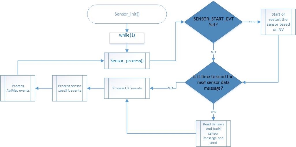
Figure 26. Sensor Example Application Task Flow Chart
Figure 26. shows various reasons for posting to the semaphore, causing the task to become active.
Events Signaled Through the Internal Event Variable
The Application task uses an event variable bit mask to identify what action caused the process to wake up, and takes appropriate action. Each bit of the event variable corresponds to a defined event such as:
/*! Event ID - Start the device in the network */
#define SENSOR_START_EVT 0x0001

/*! Event ID - Reading Timeout Event */
#define SENSOR_READING_TIMEOUT_EVT 0x0002
Whichever function sets this bit in the event variable must also ensure to post to the semaphore, to wake up the application for processing. An example of this is the clock handler which handles clock timeouts.
    /* Is it time to send the next sensor data message? */
    if(Sensor_events & SENSOR_READING_TIMEOUT_EVT)
    {

#if !defined(OAD_IMG_A)

        /* In certification test mode, back to back data shall be sent */
        if(!CERTIFICATION_TEST_MODE)
        {
            /* Setup for the next message */
            Ssf_setReadingClock(configSettings.reportingInterval);
        }


#ifdef FEATURE_SECURE_COMMISSIONING
        /* if secure Commissioning feature is enabled, read
         * sensor data and send it only after the secure
         * commissioning process is done successfully.
         * else, do not read and send sensor data.
         */
        if(SM_Last_State != SM_CM_InProgress)
        {
#endif //FEATURE_SECURE_COMMISSIONING


#if SENSOR_TEST_RAMP_DATA_SIZE
        processSensorRampMsgEvt();
#else
        /* Read sensors */
        readSensors();

        /* Process Sensor Reading Message Event */
        processSensorMsgEvt();
#endif //SENSOR_TEST_RAMP_DATA_SIZE
#ifdef FEATURE_SECURE_COMMISSIONING
        }
#endif //FEATURE_SECURE_COMMISSIONING

#endif //OAD_IMG_A

        /* Clear the event */
        Util_clearEvent(&Sensor_events, SENSOR_READING_TIMEOUT_EVT);
    }
When adding an event, it must be unique for the given task and be a power of 2
(so that only 1 bit is set). Because the event variable is initialized as
uint16_t, this setup allows for a maximum of 16 internal events.
Callbacks
The application code also likely includes various callbacks from the protocol
stack layer and RTOS modules. To ensure thread safety, processing should be
minimized in the actual callback, and the bulk of the processing should be done
in the application context. The following code snippet directs the callbacks
through ApiMac_processIncoming() to the correct MAC API using the
OSALPort after all the application events are processed.
void Sensor_process(void)

{
    /* Start the collector device in the network */
    if(Sensor_events & SENSOR_START_EVT)
    {
        ..
    }

    /* Is it time to send the next sensor data message? */
    if(Sensor_events &SENSOR_READING_TIMEOUT_EVT)
    {
        ..
    }

    /* Process LLC Events */
    Jdllc_process();

    /* Allow the Specific functions to process */
    Ssf_processEvents();

#ifdef FEATURE_SECURE_COMMISSIONING
    /* Allow the security manager specific functions to process */
    SM_process();
#endif /* FEATURE_SECURE_COMMISSIONING */
    /*
     Don't process ApiMac messages until all of the sensor events
     are processed.
     */
#ifdef FEATURE_SECURE_COMMISSIONING
    /*only if there are no sensor events and security manager events to handle*/
    if((Sensor_events == 0) && (SM_events == 0))
#else
    if(Sensor_events == 0)
#endif
    {
        /* Wait for response message or events */
        ApiMac_processIncoming();
    }
}
The previous code snippet directs the callbacks to the correct MAC API using OSALPort. Two functions are defined per callback, one at the application level, the other in the MAC API. For example, consider the handling of a scan confirm in the following code snippet.
case MAC_MLME_SCAN_CNF:
    if(pMacCallbacks->pScanCnfCb)
    {
        processScanCnf(&(pMsg->scanCnf));
    }


    if(pMsg->scanCnf.scanType == ApiMac_scantype_energyDetect)
    {
        if( pMsg->scanCnf.result.pEnergyDetect != NULL)
        {
            OsalPort_free(pMsg->scanCnf.result.pEnergyDetect);
        }
    }
    else
    {
        if( pMsg->scanCnf.result.pPanDescriptor != NULL)
        {
            OsalPort_free(pMsg->scanCnf.result.pPanDescriptor);
        }
    }

    break;
The MAC API callback is overwritten by the following application callback.
pMacCbs->pScanCnfCb = scanCnfCb; At the application level.
/*!
 * @brief       Process  Scan Confirm  callback.
 *
 * @param       pData - pointer to Scan Confirm
 */
static void scanCnfCb(ApiMac_mlmeScanCnf_t *pData)
{
    if(pData->status == ApiMac_status_success)
    {
        if(pData->scanType == ApiMac_scantype_active)
        {
            /* Only send association requests for a matching PAN */
            if(panIdMatch)
            {
                /* Set event to send Association Request */
                Util_setEvent(&Jdllc_events, JDLLC_ASSOCIATE_REQ_EVT);
            }
            else {
                /* The current scan didn't return a matching beacon */

                /* Turn off receiver until next scan if RX on idle is false*/
                if ((!CONFIG_FH_ENABLE) && (CONFIG_RX_ON_IDLE == false))
                {
                    ApiMac_mlmeSetReqBool(ApiMac_attribute_RxOnWhenIdle, CONFIG_RX_ON_IDLE);
                }

                /* schedule next scan */
                devInfoBlock.prevDevState = devInfoBlock.currentDevState;
                Ssf_setScanBackoffClock(CONFIG_SCAN_BACKOFF_INTERVAL);
            }
        }
    /* ….. */
    if(macCallbacksCopy.pScanCnfCb != NULL)
    {
        macCallbacksCopy.pScanCnfCb(pData);
    }
}
The following code is at the MAC API level.
/*!
 * @brief       Process the incoming Scan Confirm callback.
 *
 * @param       pCnf - pointer MAC Scan Confirm info
 */
static void processScanCnf(macMlmeScanCnf_t *pCnf)
{
    /* Confirmation structure */
    ApiMac_mlmeScanCnf_t cnf;

    /* Initialize the structure */
    memset(&cnf, 0, sizeof(ApiMac_mlmeScanCnf_t));

    /* copy the message to the confirmation structure */
    cnf.status = (ApiMac_status_t)pCnf->hdr.status;

    cnf.scanType = (ApiMac_scantype_t)pCnf->scanType;
    cnf.channelPage = pCnf->channelPage;
    cnf.phyId = pCnf->phyID;
    memcpy(cnf.unscannedChannels, pCnf->unscannedChannels,
    APIMAC_154G_CHANNEL_BITMAP_SIZ);
    cnf.resultListSize = pCnf->resultListSize;

    if(cnf.resultListSize)
    {
        if(cnf.scanType == ApiMac_scantype_energyDetect)
        {
            cnf.result.pEnergyDetect = pCnf->result.pEnergyDetect;

        }
        else
        {
            cnf.result.pPanDescriptor =
              (ApiMac_panDesc_t*)pCnf->result.pPanDescriptor;
        }
    }

    /*
     * Initiate the callback, no need to check pMacCallbacks or the function
     * pointer for non-null, the calling function will check the function
     * pointer
     */
    pMacCallbacks->pScanCnfCb(&cnf);
}
Non-Volatile Memory
The NV area of flash is used for storing persistent data for the application. TI
15.4-Stack uses the NV On-Chip Multi-Page (NVOCMP) driver to maintain this memory
area. Please refer to nvocmp.c which describes the implementation details of
the multi-page NV and lists the maximum values of custom NV IDs available to the
application. The last page in flash is the CCA page, the pages before that are
reserved for the NV area as defined by NVOCMP_NVPAGES. The example projects
use the NV driver with the API defined in nvintf.h.
The NV driver is set up in main.c:
#ifdef NV_RESTORE
    /* Setup the NV driver */
#ifdef ONE_PAGE_NV
    NVOCOP_loadApiPtrs(&Main_user1Cfg.nvFps);
#else
    NVOCMP_loadApiPtrs(&Main_user1Cfg.nvFps);
#endif

    if(Main_user1Cfg.nvFps.initNV)
    {
        Main_user1Cfg.nvFps.initNV( NULL);
    }
#endif
Then the applications use the function pointers in Main_user1Cfg to call the NV functions defined in nvintf.h:
//! Structure of NV API function pointers
typedef struct nvintf_nvfuncts_t
{
    //! Initialization function
    NVINTF_initNV initNV;
    //! Compact NV function
    NVINTF_compactNV compactNV;
    //! Create item function
    NVINTF_createItem createItem;
    //! Delete NV item function
    NVINTF_deleteItem deleteItem;
    //! Read item function
    NVINTF_readItem readItem;
    //! Write item function
    NVINTF_writeItem writeItem;
    //! Get item length function
    NVINTF_getItemLen getItemLen;
    //! Iterator Like doNext function
    NVINTF_doNext doNext;
    //! Lock item function
    NVINTF_lockNV lockNV;
    //! Unlock item function
    NVINTF_unlockNV unlockNV;
} NVINTF_nvFuncts_t;
The following is an example of a write from csf.c:
static void updateDeviceListItem(Llc_deviceListItem_t *pItem)
{
    if((pNV != NULL) && (pItem != NULL))
    {
        int idx;

        idx = findDeviceListIndex(&pItem->devInfo.extAddress);
        if(idx != DEVICE_INDEX_NOT_FOUND)
        {
            NVINTF_itemID_t id;

            /* Setup NV ID for the device list record */
            id.systemID = NVINTF_SYSID_APP;
            id.itemID = CSF_NV_DEVICELIST_ID;
            id.subID = (uint16_t)idx;

            /* write the device list record */
            pNV->writeItem(id, sizeof(Llc_deviceListItem_t), pItem);
        }
    }
}
The following is an example of a read from csf.c:
bool Csf_getNetworkInformation(Llc_netInfo_t *pInfo)
{
    if((pNV != NULL) && (pNV->readItem != NULL) && (pInfo != NULL))
    {
        NVINTF_itemID_t id;

        /* Setup NV ID */
        id.systemID = NVINTF_SYSID_APP;
        id.itemID = CSF_NV_NETWORK_INFO_ID;
        id.subID = 0;

        /* Read Network Information from NV */
        if(pNV->readItem(id, 0, sizeof(Llc_netInfo_t), pInfo) == NVINTF_SUCCESS)
        {
            return(true);
        }
    }
    return(false);
}
The NV system is a collection of NV items. Each item is unique and have the following pieces to it (defined in nvintf.h).:
/**
 * NV Item Identification structure
 */
typedef struct nvintf_itemid_t
{
    //! NV System ID - identifies system (ZStack, BLE, App, OAD...)
    uint8_t  systemID;
    //! NV Item ID
    uint16_t itemID;
    //! NV Item sub ID
    uint16_t subID;
} NVINTF_itemID_t;
Modifying Non-Volatile Memory Allocation
By default, TI 15.4-Stack sensor projects allocate two pages of non-volatile (NV)
memory with the pre-define NVOCMP_NVPAGES=2 inside the project’s
application → defines → sensor.opts file. This is to allow one
dedicated page for compaction and other pages for storage. This is different
from the collector project which sets NVOCMP_NVPAGES=4 inside
collector.opts to allocate three NV memory storage pages for security keys.
However, it may be necessary to increase the number of NV storage pages given
a user’s specific application. The linker command (.cmd) file alreadymodifies the defined Flash size to achieve this:
#define FLASH_BASE              0x00000000
#define FLASH_SIZE              (0x56000 - (NVOCMP_NVPAGES * 0x2000))
#define FLASH_NV_BASE           (0x56000 - (NVOCMP_NVPAGES * 0x2000))
#define FLASH_NV_SIZE           (NVOCMP_NVPAGES * 0x2000)
However a user must modify the Region Base and Region Size settings in
the project’s .syscfg file TI Drivers → NVS → Internal Flash.
For example, if NVOCMP_NVPAGES was increased to three (two pages for
storage and one for compaction) then Region Base would decrease to 0x50000
and Region Size would increase to 0x6000 (since one page of flash is 0x2000
bytes).
Note
The maximum value of NVOCMP_NVPAGES allowed is five,
which equals one compaction page (0x2000 bytes) and four storage
pages (0x8000 bytes).
TI-RTOS Drivers
The TI-RTOS provides a suite of CC13xx or CC26xx peripheral drivers that can be added to an application. The drivers provide a mechanism for the application to interface with the CC13xx or CC26xx onboard peripherals and communicate with external devices. These drivers make use of DriverLib to abstract register access.
There is significant documentation relating to each TI-RTOS driver located in the SDK. Refer to the SDK release notes for the specific location. This section only provides an overview of how drivers fit into the software ecosystem. For a description of available features and driver APIs, refer to the TI-RTOS API Reference.
Adding a Driver
Some of the drivers are added to the project as source files in their respective folder under the Drivers folder in the project workspace.
The driver source files can be found in their respective folder at
$DRIVER_LOC\ti\drivers.
The $DRIVER_LOC argument variable refers to the
installation location and can be viewed in the Project Options ->
Resource -> Linked Resources, Path Variables tab of CCS.
To add a driver to a project, include the C and include file of the respective driver in the application file (or files) where the driver APIs are referenced.
For example, to add the PIN driver for reading or controlling an output I/O pin, add the following:
#include <ti/drivers/pin/PINCC26XX.h>
Also add the following TI-RTOS driver files to the project under the Drivers\PIN folder:
PINCC26XX.c
PINCC26XX.h
PIN.h