Debug Serial Back Channel Connection
A secondary serial debug connection exists in the TI-OpenThread examples. This section will describe the physical connections needed to take advantage of the default pin mapping for this back channel.
Note
The LaunchPad VDD-IO is 3.3V, not 5V, be careful with your connections.
Multiple flying lead USB-to-Serial adaptors exist, such as:
Fixed header USB-to-Serial can also be used with jumper wires, like:
Or the UART back-channel on a second LaunchPad could be used by jumpering the TXD and RXD headers.
An example setup with the USB to TTL Serial Cable can be seen in Figure 90.
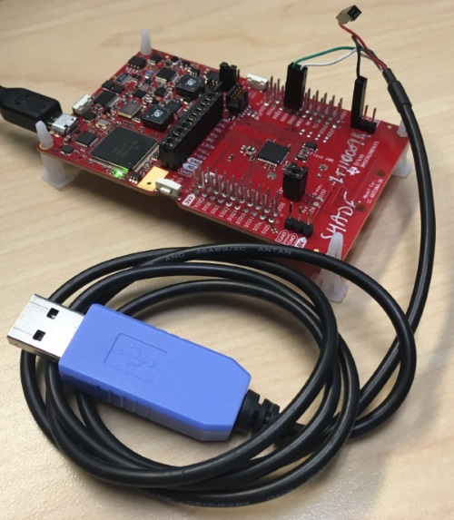
Figure 90. USB to TTL Serial Cable connections to the CC13xx or CC26xx LaunchPad
The default routing for the CC13xx or CC26xx LaunchPad are connections are board TX is DIO18
and board RX is DIO19. The corresponding connections for the USB to TTL
Serial Cable are as follows:
Color |
Connection |
Pin |
|---|---|---|
Green |
Transmit from USB |
|
White |
Receive from USB |
|
Black |
Ground |
|
Red |
VCC |
No Connect |
Warning
Consult the datasheet for your USB-to-Serial connection before powering the device.