Defining Application Behavior
The Sample Applications will often contain simple TI-RTOS tasks with a barebones messaging system between tasks. For more information on how the application tasks works in general, review Introduction.
Directed Advertisements as GATT Server
In BLE5-Stack 1.01.11.00, Privacy is always enabled. Most of the privacy features are handled by the GAP bond manager in the stack. To conserve flash memory, by default, the GAP bond manager does not enable GATT client features. The implication of these disabled GATT client features is that the GAP bond manager will not query the Central Address Resolution characteristic of the remote device.
In order to perform a directed advertisement when the initiator’s address is set to Private Resolvable Address, the peripheral device must read the Central Address Resolution characteristic of its remote device to make sure address resolution is supported. Failure to do so before sending directed advertisements violates the Bluetooth Core Specification Version 5.1.
By default, sample applications such as simple_peripheral does not define
GATT_NO_CLIENT but initializes the GATT Client as shown below:
/*
 * Initialize GATT Client, used by GAPBondMgr to look for RPAO
 * characteristic for network privacy
 */
GATT_InitClient();
Compiler Options
For BLE5-Stack projects, compiler options are defined via .opt files that are
included in the IDE’s TOOLS\defines folder. Each project’s build
configuration will include its very own .opt file.
The predefined symbols in the .opt files are prefixed with a -D, which
is standard commandline prefix notation across all the supported toolchains.
Of the predefined symbols in the .opt files, some of them are configurable
and some are not. See Bluetooth Low Energy Application Configuration Parameters and
Bluetooth Low Energy Stack Configuration Parameters for reference as to which options are
configurable.
The convention to disable a symbol in the .opt files is to put an ‘x’ in
front of the name. For example, to disable power management,
change -DPOWER_SAVING to -DxPOWER_SAVING. It is also possible to
disable a symbol by commenting it out via ‘C - style’ syntax
(e.g. /* -DPOWER_SAVING */)
Warning
Changes in an .opt file may not be detected by the compiler/toolchain.
It is best to rebuild the entire project when a define is changed.
Linker Options
Linker symbols may need to be set or adjusted at the project level in order to control the memory layout of the generated image. The following procedure describes how to access and modify linker symbols.
CCS
- Open Project Properties
- Navigate to Build -> ARM Linker -> Command File Preprocessing
- Use the buttons highlighted in Figure 87. to add, delete, or edit a linker symbol.
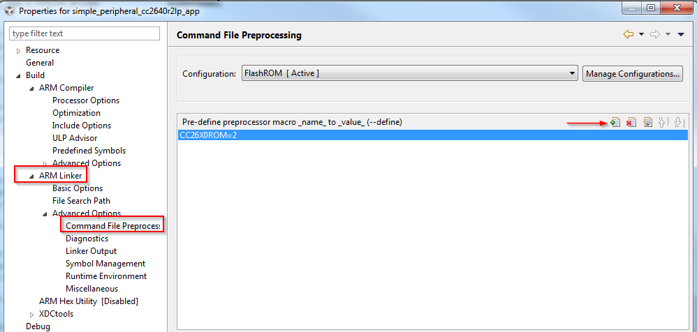
Figure 87. CCS Linker Symbols
IAR
- Open the Project’s Options and select the Linker Category.
- Open the Config tab.
- View the Configuration File symbol definitions box (see Figure 88.).
- Add or edit the preprocessor symbols.
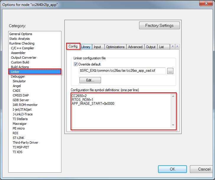
Figure 88. IAR Defined Symbols Box
Creating Additional ICall Enabled Tasks
The objective of this section is to familiarize the programmer with the process of adding an RTOS task that can communicate with the BLE5-Stack. Tasks call functions within the BLE5-Stack must follow a few additional steps to register with ICall. These details are covered below:
1. Follow all the steps detailed in Tasks to create a TI-RTOS task.
- Modify the task’s init function to register with ICall (explained in ICall Initialization and Registration)
- Modify the task’s main function to pend on
syncEvent(explained in ICall Thread Synchronization)
- Modify number of ICall enabled tasks:
- Increase the following preprocessor defines:
- ICALL_MAX_NUM_TASKS (App)
- OSAL_MAX_NUM_PROXY_TASKS (Stack)
- See Compiler Options for steps on how to change symbols.
Warning
If (OSAL_MAX_NUM_PROXY_TASKS + 1) != ICALL_MAX_NUM_TASKS the stack will abort.
- Modify number of ICall entities:
- Increase the following preprocessor defines:
- ICALL_MAX_NUM_ENTITIES (App)
For further description of the above preprocessor defines, please see Table 17.
Production and Direct Test Mode (PTM, DTM)
This page will describe Production Test Mode (PTM) which allows a CC2640R2 BLE application in a “single-chip” configuration to temporarily expose the host control interface (HCI) test commands over the serial interface when triggered externally to do so (e.g. holding a GPIO pin low during power up). This test mode allows the device to be connected to a Bluetooth RF Tester in order to run Direct Test Mode (DTM) commands on a production line using the final release firmware, while leaving the UART GPIO pins available for the application to use at all other times. Note that this page only considers UART, and not SPI, as the transport protocol since it uses the least amount of GPIO’s and throughput is not a factor for DTM.
Note
Note: DTM defines two interface methods for controlling the LE PHY: HCI and 2-wire UART. The TI Bluetooth Low Energy protocol stack only supports the HCI method for DTM and PTM.
Direct Test Mode (DTM)
DTM is a standard method for testing BLE devices using the DTM HCI commands. A number of wireless test equipment manufactures, including Anritsu (MT8852B), Keysight and Rhode and Schwarz, make BLE Testers that use this mode. It is very useful to use these testers during development or on the production line in order to verify the RF performance of a BLE system. Complementary to these testers, it is also possible to create your own PC application that sends these DTM commands over the serial link. DTM is very well described in the Bluetooth Core Specification Version 5.1 Volume 6 Part F. All DTM commands as well as TI Vendor Specific modem test commands are accessible in embedded (single-device) application via API calls as well as over HCI in the Host_Test sample application. Refer to the TI Vendor Specific HCI guide in the documents folder of the SimpleLink CC2640R2 SDK.
Production Test Mode (PTM)
One problem with DTM is that it relies on a certain stack configuration
(network processor with HCI exposed over UART) in order to work with the
testers, though many end-applications don’t use this configuration.
This would require the customer, during production, to flash the wireless
MCU with a network processor image (e.g., host_test) before testing, and
then re-flash with the final product image. To circumvent this, the TI
BLE-Stack has implemented a feature called Production Test Mode (PTM), which
allows for an embedded software application to support direct test mode without
exposing the HCI to the UART pins under normal operation.
Note that the pins used for PTM can also be used for an application UART
interface. In this case, it is necessary to ensure that the other device that
is connected to the UART interface does not run at the same time that DTM is
being exercised. If the device powers up and goes into PTM mode (by a GPIO
being held high or low or some other stimulus), the UART will then be used for
DTM commands. If the device powers up normally and does not go into PTM mode,
then the UART can be initialized by the application and used to communicate
with the other device.
DTM commands can also be called by the embedded BLE application.
Those wishing to use PTM in their application, should reference the _PTM_
configuration of the simple_peripheral project. Diffing this build
configuration to the default build configuration should show the steps needed
to enable PTM mode.
Tip
When adding PTM mode to the application, it is recommended to change the
NPI task to use Task_create(...) as opposed to construct. In this way,
the RAM needed by the NPI runtime task stack is consuming RAM that is
not used in the application’s default behavior.
In order to determine if a command is accessible via PTM mode, users should
refer to the translation tables created in icall_hci_tl.c under the define
PTM_MODE.
Note: Out of box PTM builds does not support enabling gapbondmgr due to the limited flash space.
Optimizing Bluetooth Low Energy Stack Memory Usage
Configuration of the Bluetooth Low Energy protocol stack is essential for maximizing the amount of RAM and flash memory available for the application. Refer to Stack Configurations to configure parameters that impact runtime RAM usage, such as the maximum allowable size and number of PDUs. The TI Bluetooth Low Energy protocol stack is implemented to use a small RAM footprint, and allow the application to control the behavior of the stack by using the runtime ICall heap. For example, an application that only sends one GATT notification per connection event must store only one PDU in the heap, whereas as an application that must send multiple notifications must enqueue multiple PDUs in the heap.
To increase the available flash memory allocated to the application project, minimize the flash usage of the protocol stack by including only Bluetooth Low Energy features required to implement the defined role of the device. The available protocol stack configurable features are described in Stack Configurations. Adding additional features to the protocol stack has the net effect of reducing the amount of flash memory to the application.
Flash optimization
The following tips may be useful for reducing the footprint of the BLE5-Stack. In general, there is a feature vs. flash footprint tradeoff. Each of the improvements below offer a cost in terms of feature removal.
- Verify that your application uses the optimize for flash size compiler optimization settings (default for TI projects).
- Use only one page of SNV or do not use any NV pages if the GAP bond
manager is not required. Set the
NO_OSAL_SNVstack preprocessor option. See Using Simple NV for Flash Storage for a description of SNV. - Exclude the GATT client functionality by defining the
GATT_NO_CLIENTpredefined symbol in the stack project for peripheral devices. Alternatively, if you’re using a single-project example, theStackWrapper.amust be replaced withStackWrapper_GattNoClient.ain the Linker file search paths. This should only be done by devices that do not wish to discover the RPAO characteristic. - Remove or exclude debug DISPLAY, Two button menu or other unused drivers from your project.
- Use the stack library options defined in
build_config.optto pull in the smallest library available for the given use case. In general, this means a library that implements only one role (i.e. peripheral) with no additional features enabled (i.e. L2CAP CoC). See Stack Configurations. - Remove HAL Asserts by removing the
EXT_HAL_ASSERTdefine
Disable LE Secure Connections pairing if not needed. See LE Secure Connections on how to do this. Once LE Secure Connections is disabled, then all the functions in
ECCROMCC26XX.ccan be stubbed out to simply returnECCROMCC26XX_STATUS_SUCCESS. Note that the ECC driver must still be present in the build, but stubbing the functions will save around 1.3kB of flash.1 2 3 4 5
int8_t ECCROMCC26XX_genKeys(uint8_t *privateKey, uint8_t *publicKeyX,
                        uint8_t *publicKeyY, ECCROMCC26XX_Params *params)
{
  return (ECCROMCC26XX_STATUS_SUCCESS);
}
If LESC is removed as above, then any code referencing
SECURE_CONNS_CFGcan be removed.
RAM optimization
The following tips may be useful for reducing the RAM footprint of the BLE5-Stack. It is important to remember that often removing RAM results in reduced throughput or features, the tradeoffs listed below should be evaluated carefully.
If using L2CAP CoC, reference RAM Considerations for defines that may configure L2CAP CoC functionality and their RAM implications
Set
MAX_NUM_PDUandMAX_PDU_SIZEto reduce the amount of packets that can be queued up by the stack at a time. This will reduce heap consumption.Disable LE Secure Connections pairing if not needed. See LE Secure Connections on how to do this. This will save
ECCROMCC26XX_NIST_P256_WORKZONE_LEN_IN_BYTESduring pairing. Removing LESC also removes the requirement of havingMAX_PDU_SIZEset to 69, this can be overriden inble_user_config.hto as low as 27.The LE Data Length Extension feature will default to an RX size of 251. If the peer device also supports DLE and a
connMaxRxOctetsvalue is negotiated > 27 (default) then the controller will allocate connMaxRxOctets*4. 4 is the number of receive buffers in the controller and is a fixed parameter of the stack. However, connMaxRxOctets can be limited by either disabling Data Length Extension or limiting the max of TX and RX ocetets. Trimming the values of TX and RX is covered in RAM Considerations when using DLE.Carefully set
MAX_NUM_BLE_CONNS. This define has a large affect on the amount of dynamic memory used by the stack. Below is a list of structures that the stack will alloc on initialization based on number of Connections. Each structure is multiplied byMAX_NUM_BLE_CONNS. This is not an exhaustive list A rule of thumb is that the stack will allocate the sizes of the structures above on initialization, and around ~(1070 + connMaxRxOctets*4) per connection on connect.sizeof(linkDBItem_t): Link data base entry for each connectionsizeof( l2capChannel_t ): At least one signaling channel for each connectionsizeof(prepareWrites_t): Structure to hold prepare write tableGATT_MAX_NUM_PREPARE_WRITES * sizeof( attPrepareWriteReq_t ): Prepare write queue.sizeof(llConnState_t): Structure to hold connection information2*sizeof(dataQ_t): Each connection’s RX and TX data queue
Check for heap failures by checking
heapmgrMemFailfrom Debugging Common Heap Issues. If heap failures are occurring, attempt to tune stack build configuration using the features and defines above. See Stack Configurations for options that can be configured in the stack.If heap failures still occur after optimizing the BLE-Stack build, the size of the heap can be increased by reducing the size of static allocation. Static allocation (.bss, .data) includes globally defined buffers, runtime task stacks, and other structures that are instantiated without the use of malloc.
- Trim task stack sizes by inspecting them using Task –> Detailed view in TI-RTOS Object Viewer. If there is unused space their size can be decreased.
- The system stack can be reduced in a similar way, its usage is shown under HWI –> Module view in ROV. Changing the system stack size is covered in System Stack.
Warning
The above RAM estimations may vary by release, and are not an exhaustive list. It is intended as a way to allow the developer to profile the RAM requirements based on the desired settings. The best way to estimate RAM usage is to measure it in the field using the techniques covered in Debugging Common Heap Issues
See Check System Flash and RAM Usage With Map File for the procedure to check the size of the configured protocol stack.
Decrease flash consumption of the examples project
The guidelines provided here are based on the simple_peripheral example but can be adapted to any example.
Remove the #2 (long range) advertisement
By removing the secondary advertisement (sometimes called “long range” advertisement) from the simple_peripheral example you can significantly save power. The power consumption due to the secondary advertisement (generally long range advertisement) can represent up to 80% of the power consumption of the advertisement period. In addition, this helps you to save memory.
Here are the guidelines:
Import the ble5_simple_peripheral project
Modify
simple_peripheral.cto remove the code related to the #2 advertisement.- remove the declaration of the variable
advHandleLongRange - remove all the code referencing the variable
advHandleLongRange
Here is
simple_peripheral.cdiff file (based on SDK 4.10):- remove the declaration of the variable
Build and test your project… No warning or error should be raised at build time and the project should still work smoothly! It means you can still advertise (legacy advertisement only), join a connection, pair with another device, etc…
Remove the auto-PHY update
The auto-PHY update is a feature provided by the application and consisting in dynamically change the PHY used by the BLE stack to handle a connection. The PHY is selected based on the RSSI measured. The better the RSSI, the faster the PHY selected is (e.g. if the RSSI is -25, then the 2M PHY will be selected, if the RSSI is -65 then the S8 PHY will be selected). This functionality is available in the simple_peripheral project and has to be activated using the two buttons menu. Other projects provide this functionality too.
This modification should free up some FLASH and some CPU time. The amount of stack required by the example should be decreased too. The goal is to remove the code responsible for the auto-PHY update. As the auto-PHY update is based on RSSI, we are also going to remove the code responsible to read the RSSI of the connection.
Here are the guidelines:
Import the ble5_simple_peripheral project
Modify
simple_peripheral.candsimple_peripheral_menu.c:- In
simple_peripheral.c:- Remove the function
SimplePeripheral_processCmdCompleteEvtand its calls - Remove the function
SimplePeripheral_initPHYRSSIArray()and its calls - Remove the function
SimplePeripheral_startAutoPhyChange()and its calls. - Remove the function
SimplePeripheral_stopAutoPhyChange()and its calls - Remove the function
SimplePeripheral_updatePHYStat()and its calls - Modify the function
SimplePeripheral_doSetConnPhy()in order to remove the support of theAUTO_PHY_UPDATE - Remove the callback function
SimplePeripheral_connEvtCB() - Remove the RSSI thresholds defined (this does not save any FLASH
or RAM but it these defines are useless now). Same remark for
SP_MAX_RSSI_STORE_DEPTH,SP_RSSI_TRACK_CHNLS. You can also remove all the define related to auto-phy update:SP_PHY_NONE,SP_INVALID_HANDLEandAUTO_PHY_UPDATE - Modify the
spConnRec_tstructure. We don’t need anymore the RSSI related elements (rssiArr,rssiCntr,rssiAvg) and the PHY change related (currPhy,rqPhy,phyCngRq,phyRqFailCnt,isAutoPHYEnable). Remove all the code referring to these elements.
- Remove the function
- In
simple_peripheral_menu.c:
- In the “ConnPhy” menu, remove the
MENU_ITEM_ACTIONassociated with the auto-PHY update. - In the corresponding
MENU_OBJ, modify the number of available items.
Here are the diff files (based on SDK 4.10):
simple_peripheral.csimple_peripheral_menu.c
- In
Test your code. It should still compile and work smoothly! It means you can still advertise, join a connection, pair with another device, change the Phy, etc…
Remove the connection parameters update
Once a connection has been formed, one of the two devices might want to modify the connection parameters (connection interval, slave latency, connection timeout). This can be done using a connection parameters update request.
By default, some of the examples provided (e.g. simple_peripheral) send a connection parameters update request right after being connected. By default, the examples are also able to accept a connection update. Let’s see how to not send connection update request and to deny the incoming connection updates. Note that you can choose to apply only one of the two modifications or both of them. The goal is to save flash space and CPU time.
Import the ble5_simple_peripheral project
Modify
simple_peripheral.cin order to deny all the connection parameters update requests.- Set the defined symbol
DEFAULT_PARAM_UPDATE_REQ_DECISIONtoGAP_UPDATE_REQ_DENY_ALL. As a result, connection update requests will not be anymore passed to the application. - As a result (still in
simple_peripheral.c), remove all the code executed when aGAP_UPDATE_LINK_PARAM_REQ_EVENTis received. (AGAP_UPDATE_LINK_PARAM_REQ_EVENTis triggered at the reception of a connection parameters update requests.)
Here is
simple_peripheral.cdiff file (based on SDK 4.10):- Set the defined symbol
Modify
simple_peripheral.cin order to remove the code related to connection update:Remove the treatment of the
GAP_LINK_PARAM_UPDATE_EVENT(this event is posted when a connection updated has been attempted)Remove the
SimplePeripheral_processParamUpdate()functionRemove the treatments of
SP_SEND_PARAM_UPDATE_EVTIn
SimplePeripheral_addConn(), remove the code corresponding to connection parameters update.Modify the
spConnRec_tstructure to remove the elementspParamUpdateEventDataandpUpdateClock. Remove the code using those elements too.Remove the list
paramUpdateList(and the code referring to).Remove the function
SimplePeripheral_clearPendingParamUpdate()Here is
simple_peripheral.cdiff file (based on SDK 4.10):
Test your code. It should still compile and work smoothly! It means you can still advertise, join a connection, pair with another device, change the Phy, etc…
Remove the pairing capabilities
Pairing is the process of generating and exchanging keys (not to be confused with forming or establishing a BLE connection between two devices). The pairing capability is included in many examples provided in your SDK.
As bonding consists in storing the keys generated during the pairing process in nonvolatile memory to use for the next encryption sequence, this functionality will be removed too.
This modification should free up some FLASH and some CPU time.
Some examples (e.g. simple_peripheral) provide a way to remove the code
related to pairing and/or bonding through conditional compilation.
To know if this the case of your project, verify if you can find
preprocessor directives like #if defined(GAP_BOND_MGR).
In this case, only the bullets
1. (project import), 2. ( build_config.opt modification) and 4. (test)
need to be done.
Import the ble5_simple_peripheral project
Modify
build_config.optin order remove theGAP_BOND_MGRsymbol. The filebuild_config.optis generally stored in the TOOLS folder (in the stack project’s TOOL folder for the examples having a separated app and stack projects). You can basically remove the line-DGAP_BOND_MGRor comment it out using C comments style (/*comment*/).Modify
simple_peripheral.cin order to not allow pairing and remove all the code related to pairing and/or bonding.In
SimplePeripheral_init(), remove the code related to the GAP Bond Manager setup. Remove also the call to the functionGAPBondMgr_Register().Remove the functions
SimplePeripheral_passcodeCb()andSimplePeripheral_pairStateCb().Remove the structure
SimplePeripheral_BondMgrCBs.In
SimplePeripheral_processPairState()remove the call toGAPBondMgr_PasscodeRsp().Here is
simple_peripheral.cdiff file (based on SDK 4.10):
Test your code. It should still compile and work smoothly! It means you can still advertise, join a connection, change the Phy, etc…
Remove the Resolvable Private Address (RPA) functionality
(Random) Resolvable Private Address or RPA is a functionality helping to preserve privacy. It consists in changing the device address over time. The address can be matched, or resolved, to an Identity Address for tracking by trusted peers.
This functionality is provided in several examples and can be removed in order to save memory and CPU time.
Some examples (e.g. simple_peripheral) provide a way to remove the code
related to RPA through conditional compilation.
To know if this the case of your project, verify if you can find
preprocessor directives like
#if defined(BLE_V42_FEATURES) && (BLE_V42_FEATURES & PRIVACY_1_2_CFG).
In this case, only the bullets
1. (project import), 2. ( build_components.opt modification) and 4. (test)
need to be done.
Import the ble5_simple_peripheral project
Modify
build_components.optin order to not activate all the privacy features. This must be done by changing the value of the defined symbolPRIVACY_1_2_CFG.> Find the line
-DPRIVACY_1_2_CFG=0x01and change it in-DPRIVACY_1_2_CFG=0x00Modify
simple_peripheral.cin order to remove all the code related to RPA.Remove the function
SimplePeripheral_updateRPA()and all its calls.Remove the code sending or treating the
SP_READ_RPA_EVT_PERIODevents.Remove the global variable
rpa[].Here is
simple_peripheral.cdiff file (based on SDK 4.10):
Test your code. It should still compile and work smoothly! It means you can still advertise, join a connection, change the Phy, etc…
Optimize TI drivers for your project
In order to have easy-to-use and portable code, the TI drivers handle a lot of different configurations. Most of the time, a specific application does not require all those configurations. By optimizing the TI drivers for your own application you can save RAM, FLASH and processor time.
A good example of this is the Power driver (but you can analyze any TI driver in order to optimize it using a similar process). The Power driver is a pretty complex driver. A lot of different combinations of crystals can be used and it handles all of them.
Let’s see how to optimize the Power driver:
Force CCS or IAR to not use the compiled sources for the Power driver.
[CCS] Right click on your project and click “Add Files…” Add the files PowerCC26XX.c and PowerCC26XX.h to your project. (The TI drivers files are stored in <Your SDK>/source/ti/drivers)
It is recommended to select Copy Files and not Link to files.
Verify if the linker is considering the files you added by checking the “MODULE SUMMARY” section of the .map file. You should find a line presenting the memory consumed by
PowerCC26XX.obj.
- [IAR] Right click on your project, then chose “Add” and “Add Files…”. Add the files PowerCC26X2.c and PowerCC26X2.h to your project. (The TI drivers files are stored in <Your SDK>/source/ti/drivers)
- Review the configuration of your project (for the Power driver,
the crystal configuration is the most important). To do so, use
SysConfigand/or consult the fileti_devices_config.c. IfSysConfigis not used, consult the fileccfg.c.
Optimize the code! The goal here is to find the variables that are not seen as constant by the code optimizer but that are constant in practice.
a- Expressions returning always the same value for a given configuration:
CCFGRead_DIS_GPRAM()CCFGRead_SCLK_LF_OPTION()OSCClockSourceGet(OSC_SRC_CLK_LF)OSCClockSourceGet(OSC_SRC_CLK_HF)
Those expressions can be replaced by their constant value. This will allow the code optimizer to generate a simpler code.
b- Variable that won’t be used (or that will always the same value).
- Function pointer never set (i.e. always pointing on NULL). In this case no need to test if the function is not NULL, just remove the corresponding code. (The Power driver for CC2640R2 does not contain any example of this case.)
- Variable with a constant value set only once at driver opening. (The Power driver does not contain any example of this case.)
That’s it! Once again, these guidelines can be adapted to all the drivers used. It is important to test properly your code once optimized to be sure that no unexpected behavior occurs.
Defining Bluetooth Low Energy Behavior
This step involves using Bluetooth Low Energy protocol stack APIs to define the system behavior and adding profiles, defining the GATT database, configuring the security model, and so forth. Use the concepts explained in BLE5-Stack as well as the Bluetooth Low Energy API reference in BLE Stack API Reference.