This section will explain how to adapt a BLE application from the SimpleLink CC2640R2 SDK to run on custom hardware. In general, the steps required to migrate a BLE application from a development kit to a custom board are minimal and involve changing the pin configuration as well as selecting the correct RF configuration. These steps, including a bring up guide, are detailed in the subsections below.
TI Provided Board Files
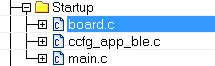
In order to make the SimpleLink CC2640R2 SDK’s sample applications portable across different board and package types, a high level gateway file is used to select the proper board file based on the <board_type> predefined symbol. The top-level board file (board.c) then uses this symbol to include the correct board file into the project. This top-level board file can be found at <SDK_INSTALL_DIR>\source\ti\blestack\target\board.c, and is located under the Startup folder in the project workspace:
The board file links in another gateway board file located at <SDK_INSTALL_DIR>\source\ti\blestack\target\<kit_type>, which finally links in the actual board file from <SDK_INSTALL_DIR>\source\ti\boards\<board_type>.
<kit_type> indicates a handful of reference board files supported by the SimpleLink CC2640R2 SDK such as:
- cc2640r2em
- cc2640r2lp
- cc2640r2rc
Warning
The <kit_type> is an intermediate step within the board gateway and will not need to be modified by the user while running on a TI EM or LP. Don’t try to set <kit_type> as a predefined symbol in your application.
The <board_type> define is set by the app project’s predefined symbols. The following defines are supported by the SimpleLink CC2640R2 SDK and refer to a reference design (EM or LaunchPad) created by TI.
By changing the define above, the application project will pull in a board file that is adopted for the TI reference designs or development kits with same name. Click the links above for more information on their respective TI reference designs.
Note
The CC2640R2 is pin compatible with the CC2650 and CC2640 wireless MCUs in equivalent QFN package sizes, so the above reference designs can be used when designing with the CC2640R2.
Note that within the <board_name>.h file the symbol used to select the board’s
RF front end configuration will be defined. See ble_user_config.h and
Configuring the RF Front-End for Custom Hardware for more
information on available RF front end configurations.
Package Type and Board Files
Most of the examples within the SimpleLink CC2640R2 SDK will run on the CC2640R2F LaunchPad out of the box. Board files based on the TI CC26xx evaluation module (EM) reference designs are also provided for your convenience. (See TI Provided Board Files for more info) However, for custom hardware designs it may be necessary to modify the provided board files based on your selected package and RF configuration.
The board file for CC2640R2_LAUNCHXL is made for the 7x7 mm QFN package using differential RF front end and internal biasing. To convert this board file to use for other smaller device packages (5x5 mm and 4x4 mm QFN), the board file will need to be modified since limited number of IO pins are available in the smaller packages.
Note
It is recommended to start customizing board file(s) based on a reference design that is similar to your selected package type and RF configuration. For example a design for a 5x5 mm QFN package with a differential front end and external bias should use the CC2640R2DK_5XD board files as a reference.
See the datasheet for all the package options and IO descriptions: CC2640R2F Datasheet
For example, to change to the 4x4 package, remove all defines for all IOs not available (IOID_10 and higher) since the 4x4 package has only 10 DIO pins as listed in the datasheet.
The table below shows the number of GPIOs supported by each package:
| Package Option | Total GPIO Pins | MAX IOID |
|---|---|---|
| 7x7 mm QFN | 31 | IOID_30 |
| 5x5 mm QFN | 15 | IOID_14 |
| 4x4 mm QFN | 10 | IOID_9 |
| 2.7 x 2.7 mm WCSP | 14 | IOID_13 |
Creating a Custom Board File
TI-RTOS drivers rely on “board files” for their board-specific configuration
parameters. The convention is to name these files based on the development kits
provided by TI in addition to a generic Board.h with Board_* definitions
to map the proper pins defined by ioc.h.
For example, for the simple_peripheral project, the following comprise the set of board files used by the CC2640R2 LaunchPad development kit:
Board.h CC2640R2_LAUNCHXL.h CC2640R2_LAUNCHXL.c
Note
simple_peripheral board files are located in
<SDK_INSTALL_DIR>\source\ti\boards\CC2640R2_LAUNCHXL
TI recommends to start with the existing set of board files when porting a BLE application to custom development boards. When modifying or porting these board files, the user should consult with TI Drivers API Reference.
Tip
Board files provided by TI include TI-RTOS driver configuration data structures for various drivers. If the application does not use the associated TI-RTOS drivers, the linker will simply omit them from the application image.
The following steps provide guidance on customizing board files for a BLE-Stack 3.03.08.00 project.
Duplicate existing board files from existing CC2640R2_LAUNCHXL board files.
- These files can be found at:
<SDK_INSTALL_DIR>\source\ti\boards\CC2640R2_LAUNCHXL - Create a copy of the
CC2640R2_LAUNCHXLdirectory and give it a unique meaningful name for your development platform. In this example, we call itMYBOARD.
Caution
The SimpleLink CC2640R2 SDK also contains board files for TI-RTOS kernel and driver examples. These are not compatible with the BLE-Stack 3.03.08.00 because of differences in RF driver SWI priorities and custom drivers (e.g. TRNG) required by BLE-Stack 3.03.08.00. For BLE-Stack projects, use the files specified above for reference from simple_peripheral.
- In the
MYBOARDdirectory, renameCC2640R2_LAUNCHXL.candCC2640R2_LAUNCHXL.hto theirMYBOARD.candMYBOARD.hrespectively. - Search and replace all references of
CC2640R2_LAUNCHXLwithMYBOARDinBoard.h,MYBOARD.candMYBOARD.h.
- These files can be found at:
Add a new preprocessor define in your project’s
board.candboard.hfiles.Continuing with the
MYBOARDexample, modifyboard.candboard.hin<SDK_INSTALL_DIR>\source\ti\blestack\targetReplace
CC2640R2_LAUNCHXLbyMYBOARDin your project’s application predefined symbols (See Accessing Preprocessor Symbols or Accessing Preprocessor Symbols)In
board.h, add a link to yourBoard.hfile.1 2 3 4
#elif defined(CC2640R2_LAUNCHXL)
    #include "./cc2640r2lp/cc2640r2lp_board.h"
#elif defined(MYBOARD)
    #include "../../boards/MYBOARD/Board.h"
In
board.c, add the highlighted lines shown below:1 2 3 4 5
#elif defined(CC2640R2_LAUNCHXL)
    #include "./cc2640r2lp/cc2640r2lp_board.c"
#elif defined(MYBOARD)
    #include "../../boards/MYBOARD/Board.h"
    #include "../../boards/MYBOARD/MYBOARD.c"
Explicit references to
CC2640R2_LAUNCHXL.hneed to be replaced byMYBOARD.h
Modify board files to match application requirements
- PIN structure to match the layout of the board.
- Add peripheral driver initialization objects according to the board design.
- For RF driver configuration, see Configuring the RF Front-End for Custom Hardware
Board Level Middleware
There are also several board driver files which are a layer of abstraction on top of TI-RTOS drivers, to function for a specific board, for example Board_key.c, or ExtFlash.c If desired, these files can be adapted to work for a custom board.
Using 32-kHz Crystal-Less Mode
BLE-Stack 3.03.08.00 includes support for operating the CC2640R2 in a 32-kHz
crystal-less mode for peripheral and broadcaster (beacon) role configurations.
By using the internal low-frequency RC oscillator (RCOSC_LF), the 32-kHz crystal
can be removed from the board layout. By removing it you lower the bill of
material (BOM) cost, reduce the required board space and simplify procurement.
On the other hand, the current consumption will vary depending on the role of the
device compared to when using the external 32-kHz crystal. More info in the
SWRA499 Applicaion Note.
Note
Following project in the SDK already have a RCOSC build configuration:
- simple_broadcaster
- host_test
- simple_np (SPI)
- simple_peripheral
There are a few steps that must be taken into account to enable this feature. For any peripheral project, the following change is required for IAR. CCS users should see the Running Bluetooth Low Energy on CC2640 Without 32 kHz Crystal for the needed steps to enable RCOSC_LF in a project. You will find more detail regarding this feature in the aforementioned application note.
Include rcosc_calibration.c, rcosc_calibration.h and ccfg_app_ble_rcosc.c files which locate at <SDK_INSTALL_DIR>\source\ti\blestack\common\cc26xx\rcosc
Exclude ccfg_app_ble.c from build.
Add USE_RCOSC to Defined symbols.
Add the following code to your
peripheral project.c#ifdef USE_RCOSC #include "rcosc_calibration.h" #endif //USE_RCOSC
Add the following code to your
peripheral project_initfunction inperipheral project.c:#ifdef USE_RCOSC RCOSC_enableCalibration(); #endif // USE_RCOSC
If you are using a custom board file, enable the RCOSC in the power config. The board files included with the BLE-Stack:
PowerCC26XX_Config PowerCC26XX_config = {
  .policyInitFxn     = NULL,
  .policyFxn         = &PowerCC26XX_standbyPolicy,
  .calibrateFxn      = &PowerCC26XX_calibrate,
  .enablePolicy      = TRUE,
  .calibrateRCOSC_LF = TRUE,
  .calibrateRCOSC_HF = TRUE,
};
Constrain the temperature variation to be less than 1°C/sec. If the temperature is to change faster than 1°C/sec, then a short calibration interval must be used. Calibration interval can be tuned in rcosc_calibration.h
// 1000 ms
#define RCOSC_CALIBRATION_PERIOD   1000
Note
Use of the internal RCOSC_LF requires a sleep clock accuracy (SCA) of 500 ppm.
Configuring the RF Front-End for Custom Hardware
The CC2640R2 supports multiple RF front-end options to optimize performance or cost. Reference designs are available for multiple RF front-end options to aid in decoupling and RF layout. In order to achieve optimal sensitivity, it is important to configure the BLE application with the correct RF front-end setting used on the custom board. An incorrectly configured RF front-end may result in substantially degraded RF performance such as the inability to maintain a connection with a peer device. Configuration of the RF front-end is done within the board file.
For example, within the simple_peripheral project, the RF front-end
configuration is defined in CC2640R2_LAUNCHXL.h with:
1#define CC2650EM_7ID
The defined symbol is used in ble_user_config.h and ble_user_config.c
to set the correct RF front-end mode, and the select the appropriate PA table
for that configuration. In ble_user_config.h, CC2650EM_7ID is processed to
define RF_FE_MODE_AND_BIAS:
This configures the project to use a differential RF with internal bias.
Other configurations can also be found in ble_user_config.h, select the
configuration appropriate to your project.
In ble_user_config.c, CC2650EM_7ID selects the appropriate PA table,
in this case for differential RF. For CC2640R2, there are three PA tables;
one for differential operation on QFN packages, one for single ended on QFN,
and one for single ended on WCSP.
Note
There are several other parameters being configured in ble_user_config.
For CC2640R2 it is only the RF front-end mode and PA table that have to be
changed for different boards.
For information on front ends, antenna configurations and other hardware considerations, please see CC13xx/CC26xx Hardware Configuration and PCB Design Considerations.
Configuring Device Parameters for Custom Hardware
- Set parameters, such as the sleep clock accuracy of the 32.768-kHz crystal. See HCI_EXT_SetSCACmd()
- Define the CCFG parameters in ccfg_app_ble.c to enable or disable the ROM serial bootloader, JTAG access (DAP), flash protection, and so forth.
Note
For a description of CCFG configuration parameters, see the CC13x0 CC26x0 SimpleLink Wireless MCU Technical Reference Manual.
Initial Board Bring Up
When powering up a custom board with the CC2640R2 for the first time, it is recommended to follow the Board Bring-Up section on CC13xx CC26xx HW Configuration and PCB Design. After confirming that the board is being powered correctly by the battery or power supply and can be identified by the JTAG tool, programming the device with a minimal SW application to verify stability is also suggested.
TI recommends using the simple_peripheral sample application for initial board bring up with modifications to the board file to:
- Disable all GPIO pin access
- Select the correct RF front end setting.
To disable all GPIO pin configuration, set the BoardGpioInitTable in the
board file to PIN_TERMINATE:
The TI BLE-Stack does not require any GPIO pins to be configured in order to
establish and maintain a BLE connection. Ensure that Display_DISABLE_ALL
is defined in the application Predefined Symbols so that diagnostic logging
data is not routed to any GPIO pin. If your custom board uses a different device
configuration, such as the 32 kHz crystal-less RCOSC_LF configuration, be sure
to make these device changes to the project. With this minimal application
configuration you should be able to establish a BLE connection
(e.g., with a smart phone or BTool) to your board at the expected range.
If you are not able to complete this step, then it is likely there is a
misconfiguration of the RF front end or you have other board related or layout
issues.
After confirming that your board can maintain a BLE connection, you can now validate that your BLE application functions as expected on the custom board. Again, it is suggested to enable your GPIO pins one at a time in the board file and comment-out access to other GPIO pins in your application. If you do encounter a CPU exception (HWI abort) during this phase it is likely that a GPIO pin is incorrectly mapped in your custom board file or your application is attempting to access a GPIO pin that does not exist in your device package type.