RF Testing using BTool
Note
For a step by step explanation about how to execute a sequence of commands for testing, please refer to the Application Note on How to Do RF Radio Test With Your Bluetooth Product. Please consider that this guide has been specially developed for CC26xx devices but is still applicable for CC23xx devices considering differences in commands (such as the ones used for setting TX Power). Information related to Packet Error Rate (PER) and RSSI measurements can be found there.
Tool Configuration
In order to set the device to perform RF tests, we need an image capable of receive and executing HCI commands.
Flash the device with the respective
host_test example, which can be found inside the SDK folder<SDK>/examples/rtos/LP_EM_CC23xx/ble5stack/host_test. It is also possible to use projects that have Production Test Mode (PTM) enabled functionalities such as the example found in<SDK>/examples/rtos/LP_EM_CC2340R5/ble5stack/basic_ble_ptm. You can import the project in CCS or IAR and tune it to fit your own design (e.g. change the UART mapping).If your design allows it (or if you are running the tests on a TI LaunchPad), you can directly flash the pre-built hexfile on the device. To do so, use Uniflash and use the following image
<SDK>/examples/rtos/LP_EM_CC2340R5/ble5stack/hexfiles/host_test_app.hex.Finally, it is recommended to power cycle the device after flashing it.
BTool can be found within the SDK. Execute the file
<SDK>/tools/ble5stack/btool/btool.exeto open the tool.When opening BTool, you are prompt to select the COM interface used by your device. Make sure to choose the interface
COMXX - XDS110 Class Application/User UART.At start BTool automatically sends a few commands to the device. These commands are not relevant for this use case, so just wait for the commands to be executed, then right click on the log and click
Clear Log.Move to the panel
Advanced Commands. From this panel you can send commands to the device. For this use case, the commands withinHCI ExtendedandHCIshould be the most useful.Send a reset command
HCI_Reset. A UART command is sent to the device (displayed in green) and the device resets and sends back an answer.
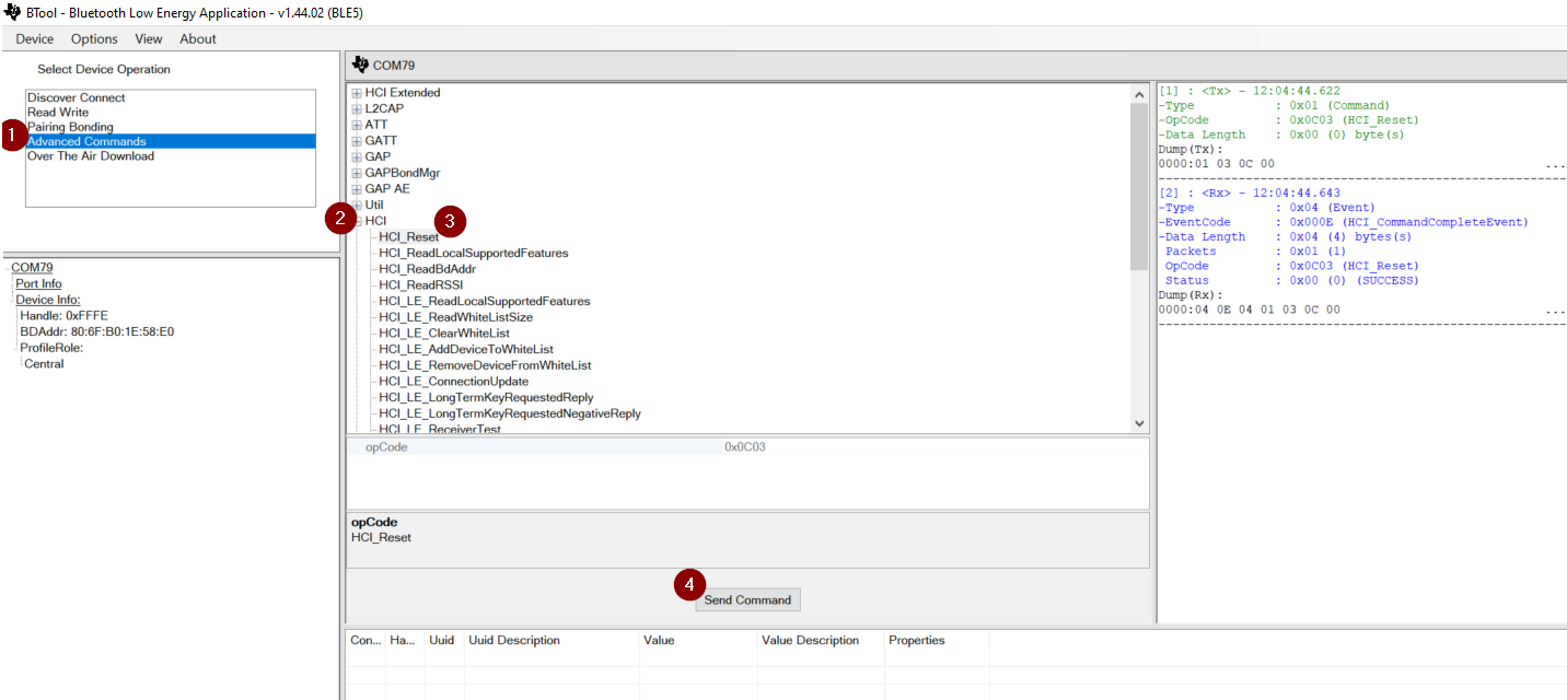
Figure 47. BTool interface - Advanced Commands
Assuming you have reached this point, it means the device is properly flashed, the UART commands are properly sent and executed by the device. Now we can look at sending more test commands to the device.
The HCI commands are specified by the Bluetooth Specifications. In order to offer more testing possibilities, these commands are completed by HCI Extended commands. Documentation for all these commands can be found in the API references section of the user’s guide.
Only a subset of the commands will be used for testing (see below). Commands in bold are the ones commonly used:
- Continuous Wave (Non-signaling)
Command
Parameters
Comments
HCI_Reset
none
To reset the device
HCIExt_EndModemTestCmd
none
To terminate a modem test
HCIExt_ModemTestTxCmd
Modulation, Channel
For the 1M PHY only
HCIExt_ModemTestRxCmd
Channel
For the 1M PHY only
HCIExt_EnhancedModemTestTxCmd
Modulation, PHY, Channel
HCIExt_EnhancedModemTestRxCmd
PHY, Channel
HCIExt_SetTxPowerDbmCmd
dBm, fraction (not used)
To set TxPower for modem tests
- Direct Test Mode - DTM (Signaling)
Command
Parameters
Comments
HCI_Reset
none
To reset the device
HCI_LE_TestEnd
none
To terminate a DTM test
HCI_LE_TransmitterTest
Channel, Data Length, Data
For the 1M PHY only
HCI_LE_ReceiverTest
Channel
For the 1M PHY only
HCI_LE_EnhancedTransmitterTest
Channel, Data Length, Payload, PHY
Payload to be selected from DTM standard
HCI_LE_EnhancedReceiverTest
Channel, PHY, modulationIndex
HCIExt_SetMaxDtmTxPowerDbmCmd
dBm, fraction (not used)
To set TxPower for DTM tests
Hands-on Examples
Let’s try some of them! You will be able to see the log that is produced in BTool. Highlighted in yellow are the commands to send and the parameters you should make sure to set. Highlighted in blue are the events received from the device (a non-SUCCESS answer means there has been an issue).
Example 1: Set the device to transmit at 8dBm a Continuous Wave with 2M PHY on channel 1.
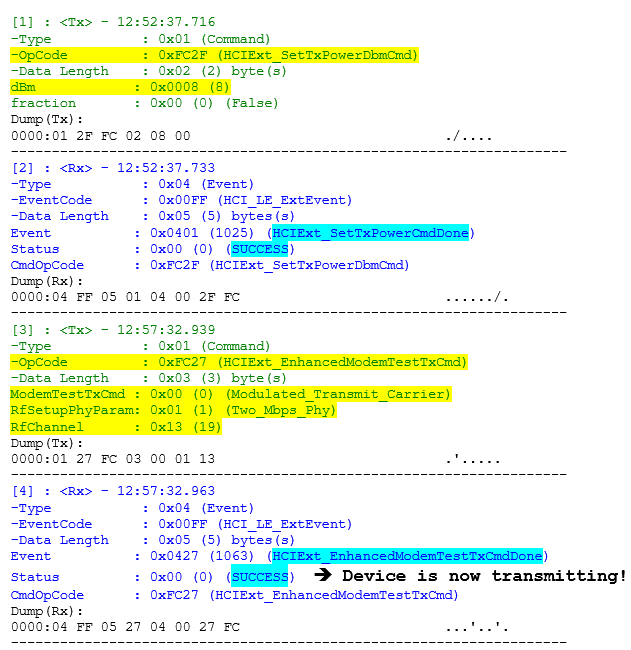
Figure 48. Display of command execution using Btool.
Example 2: Set the device to transmit at 8dBm a Continuous Wave with 2M PHY on channel 4.
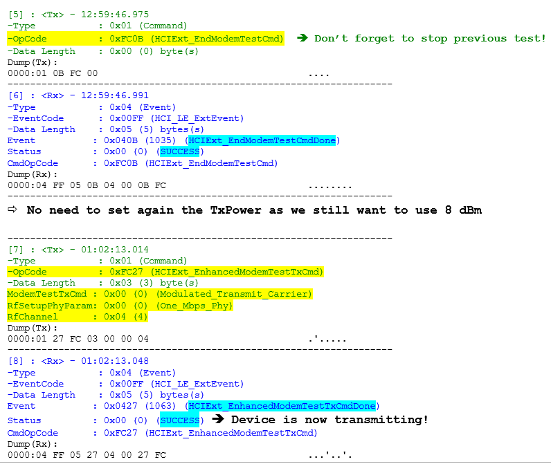
Figure 49. Display of command execution using Btool.
Example 3: Set the device to transmit DTM packets at 5 dBm with 1M PHY on channel 36 with 37-byte payload of PRBS9.
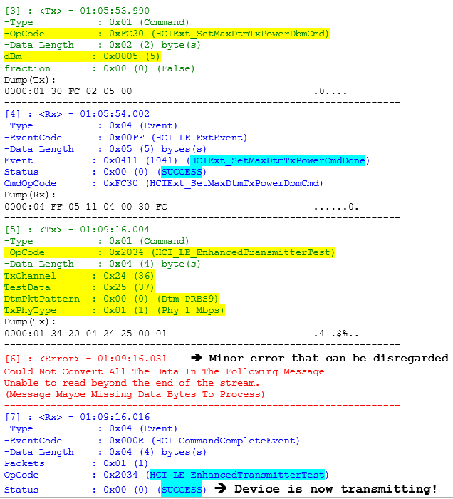
Figure 50. Display of command execution using Btool.
Example 4: Set the device to transmit DTM packets at 5 dBm with 1M PHY on channel 36 with 37-byte payload of 0b11110000.
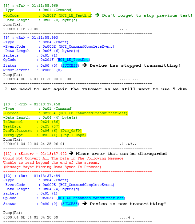
Figure 51. Display of command execution using Btool.
Example 5: Set the device to receive a Continuous Wave before ending it.
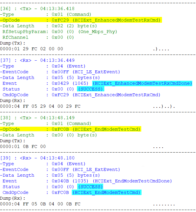
Figure 52. Display of command execution using Btool.
Warning
Command parameters (such as channel number, payload, TX power, etc) cannot be changed while a test is running. To perform such changes, you need to stop the current test by issuing the proper end commands.