Software Examples
WiFi Fundamentals
Note
Optional : Prior to testing WLAN functionality, execute ifconfig command on the console to list available interfaces. If wlan0 interface is listed, it will confirm CC3xx drivers were loaded properly.
The following sections describe the steps that can be used to verify the build for both STA and AP roles. Before proceeding
further, make sure that you have a valid image on an SD card by following the build procedures mentioned in the CC33XXSoftware Download and Installation
section. The scripts are located at /usr/share/cc33xx. Note that the configuration files needed for the wpa_supplicant and
hostapd are also included in this folder. These files may need to be modified to enable WPA2, channel selection, mode of
operation, and so forth.
STA Mode
This section explains how to configure CC33xx device to be in STA role, connect it to an Access Point and verify the connectivity between the CC33xx device and the AP. The general procedure of using the pre-built scripts for Station Mode is as follows:
Navigate to the directory which contains the out-of-box scripts as root
cd /usr/share/cc33xx/Start the device in station mode
./sta_start.shConnect to an Access Point
./sta_connect.sh -n <SSID> -s <SEC TYPE> -p <PASSCODE> -f <PMF> -u <Unicast scan> -i <interface name>

For all options call: ./sta_connect.sh -h

root@am335x-evm:/usr/share/cc33xx# ./sta_connect.sh -h
Usage: ./sta_connect.sh [OPTIONS]
Options:
  -h,   --help       Display this help
  -n,   --network    Network name (aka SSID) of the AP (required)
  -s,   --sec        Security Type: NONE, WPA-PSK, SAE, WPA-EAP, WPA-EAP-SHA256
  -p,   --password   Security Key passphrase
  -f,   --pmf        PMF: 0 - disabled, 1 - optional, 2 - required
  -u,   --unicast    Scan unicast or broadcast: 0 - broadcast (default), 1 - unicast
  -i,   --intf       Interface name: wlan0 (default), wlan1
  -------------------------------------------------------------
  Following options for enterprise only (WPA-EAP/WPA-EAP-SHA256)
  -------------------------------------------------------------
  -c    Path to client certificate file
  -K    Path to private key cert file
  -I    Identity
  -P    Private key password
Un-secured Access Point
./sta_connect.sh -n <SSID>  -s NONE
or
./sta_connect.sh -n <SSID>
Secured Access Point with WPA2 security
./sta_connect.sh -n <SSID> -s WPA-PSK -p <password>Secured Access Point with WPA2 PMF security
./sta_connect.sh -n <SSID> -s WPA-PSK -f 1 -p <password>Secured Access Point with WPA3 security
./sta_connect.sh -n <SSID> -s SAE -p <password>Request an IP address from the Access Point
udhcpc -i wlan0Ping the Access Point to verify the connection
ping 192.168.1.1An output similar to the following can now be seen:
PING 192.168.1.1 (192.168.1.1): 56 data bytes
64 bytes from 192.168.1.1: seq=0 ttl=64 time=2.369 ms
64 bytes from 192.168.1.1: seq=1 ttl=64 time=2.526 ms
The following command will display the AP settings and verify the connection:
iw wlan0 linkDisconnect from the AP and kill the supplicant by executing the following:
./sta_stop.sh
Example WPA3 Supplicant configuration
It may be useful to have a wpa_supplicant.conf that forces a connection to a WPA3-enabled
network. The configuration in /usr/share/cc33xx/wpa_supplicant.conf can then be
edited to show the following:
ctrl_interface=/var/run/wpa_supplicant
update_config=1
config_methods=virtual_display virtual_push_button keypad

network={
                ssid="<SSID>"
                sae_password="<PASSWORD>"
                proto=RSN
                key_mgmt=SAE
                group=CCMP
                ieee80211w=2
}
And then the connection can be established by simply starting the wpa_supplicant:
./sta_start.sh
AP Mode
This section explains how to configure CC33xx in the AP role, connect another Wi-Fi device to it and verify the connectivity between the connected device and the CC33xx AP.
AP Mode Procedure
The device can be configured as an AP by editing the hostapd.conf file, located at /usr/share/cc33xx/hostapd.conf.
In this file, there are options to change the SSID, security and select other advanced Wi-Fi features. The key
parameters to consider are listed below:
# SSID to be used in IEEE 802.11 management frames
ssid=CC33xxAP
# Channel number (IEEE 802.11)
channel=6
# ieee80211n: Whether IEEE 802.11n (HT) is enabled
# 0 = disabled (default)
# 1 = enabled
# Note: You will also need to enable WMM for full HT functionality.
ieee80211n=1
# ht_capab: HT capabilities (list of flags)
ht_capab=[SHORT-GI-20][GF][HT]
##### WPA/IEEE 802.11i configuration ##########################################
wpa=2
wpa_passphrase=yourpassword
# Set of accepted key management algorithms (WPA-PSK, WPA-EAP, or both). The
# entries are separated with a space. WPA-PSK-SHA256 and WPA-EAP-SHA256 can be
# added to enable SHA256-based stronger algorithms.
# (dot11RSNAConfigAuthenticationSuitesTable)
wpa_key_mgmt=WPA-PSK
# Operation mode (a = IEEE 802.11a, b = IEEE 802.11b, g = IEEE 802.11g,
# Default: IEEE 802.11b
hw_mode=g
# Pairwise cipher for WPA (v1) (default: TKIP)
wpa_pairwise=TKIP CCMP
# Pairwise cipher for RSN/WPA2 (default: use wpa_pairwise value)
rsn_pairwise=CCMP
Starting the AP
Run the ap_start script as root:
cd /usr/share/cc33xx
./ap_start.sh
Sample output:
adding wlan1 interface
Configuration file: /usr/share/cc33xx/hostapd.conf
IPv6: ADDRCONF(NETDEV_UP): wlan1: link is not ready
wlan1: interface state UNINITIALIZED->COUNTRY_UPDATE
Using interface wlan1 with hwaddr 0c:1c:57:bb:60:5f and ssid "CC33xxAP"
IPv6: ADDRCONF(NETDEV_CHANGE): wlan1: link becomes ready
cryptd: max_cpu_qlen set to 1000
wlan1: interface state COUNTRY_UPDATE->ENABLED
wlan1: AP-ENABLED
To verify that the CC33xx AP was successfully enabled, use a device such as a smart phone or laptop and connect it to CC33xx AP. A prompt (AP_STA_CONNECTED) will be visible when the station successfully connects to the CC33xx AP.
Warning
CC33xx devices do not have the capabilities to detect radar systems such as those used by weather, military, and airport radars. Therefore, the user must be careful to not set the channel in hostapd.conf to one of the 5GHz DFS channels.
Dual STA-STA Mode
The CC33xx device supports simultaneous dual STA-STA role. In other words, it is possible to have 2 station roles on CC33xx and connect to 2 seperate APs at the same time.
The primary station is by default on wireless interface ‘wlan0’. For more details on primary station, please consult STA_Mode section above. The secondary station is by default on wireless interface ‘wlan1’.
Note
Dual STA-STA mode can not be executed while AP mode is also active. Stop the AP mode by running ‘./ap_stop.sh’
Add secondary station by executing this script:
./sta_add.sh
Connect secondary station to an Access Point
Run the script "./sta_connect.sh" ( same as primary station ) to connect secondary station to an Access Point.

Add "-i wlan1" to the list of arguments in order to specify the secondary station interface

example: Connect secondary station to an Un-secured AP

./sta_connect.sh -n SSID -i wlan1
For more connect options, please consult step 3 of STA_Mode section above
Note
IEEE 802.11ax is disabled on secondary STA
Disable secondary station
ifconfig wlan1 down
Remove secondary station
./sta_remove.sh
LSI (Long Sleep Interval)
In between receiving DTIM beacons (delivery traffic indication message) from an Access Point, the device is able to go into low-power modes without the risk of missing data. The transmission time of the DTIM beacon is known in advance, so the device is able to wake up in time to receive traffic. The CC33xx device incorporates an LSI mode where the device will only wake up for a single broadcast period within the time interval specified by the application. Therefore, the device is able to reduce power consumption with the tradeoff of possibly missing broadcast data on the network.
In order to configure Long Sleep Interval for the device in STA role, use the following command where NUM is an integer value between and including 1 to 10. NUM is the number of DTIM beacons that the device will wake on. For example, if NUM is 3, then the STA will wake on every 3rd beacon. If NUM is 1, then the STA wakes on every DTIM, and disables the LSI feature:
echo NUM > /sys/kernel/debug/ieee80211/phy0/cc33xx/dtim_interval
Antenna Select Control
The antenna select pin (ANT_SEL) can be manually controlled from the linux host in order to toggle the state of the pin. By default, the ANT_SEL pin will be LOW on powerup. Issue one of the following commands to set the pin HIGH (1) or LOW (0).
# sets the ANT_SEL pin HIGH
echo 1 > /sys/kernel/debug/ieee80211/phy0/cc33xx/antenna_select
# sets the ANT_SEL pin LOW
echo 0 > /sys/kernel/debug/ieee80211/phy0/cc33xx/antenna_select
MAC Address Allocation
Each CC33xx device comes with 2 universally administered MAC addresses burned-in. One of
the addresses will be assigned for Wi-Fi and the other for BLE. However, the CC33xx
devices support up to 3 active roles on corresponding interfaces: wlan0, wlan1,
and hci0. wlan0 and hci0 are both assigned universal address, so wlan1 needs
to have a separate MAC address assigned. This is done by creating a locally administered address of the wlan0
address. Locally administered addresses are different from universally address in
that the second-least-significant bit of the first octet of the address is set to 1.
If this bit is set to 0, then the MAC address is universally administered.
The wlan0 interface could be station or AP role, depending on what the developer
requires. However, if the developer requires to use simultaneous station and AP role,
then the user must set AP role to wlan1, so as to avoid using the locally administered
MAC address on the STA role.
Override Default MAC Address
The Linux driver provides the ability to override the default MAC address. Though
there is no ability to permanently change the MAC address, developers can create
a file in the linux filesystem which the cc33xx linux driver would read and send
to the device on firmware download. This file must be placed into the /lib/firmware/ti-connectivity
directory and named cc33xx-nvs.bin. The contents of the cc33xx-nvs.bin must only
contain the binary input of the MAC address.
Creation of the cc33xx-nvs.bin file is done with the following command with the example MAC “00:11:22:33:44:55”:
echo -n -e '\x00\x11\x22\x33\x44\x55' > /lib/firmware/ti-connectivity/cc33xx-nvs.bin
If the NVS file is not present, then the default MAC address from TI will be used. An address in the NVS file with value “00:00:00:00:00:00” is reserved and the default address will also be used. A value with “00:00:00:00:00:01” is reserved and will generate a random MAC address each time the driver is initialized.
Recovery Mechanism
Should the communication between the host and the CC33XX device have a fault in communication, the CC33xx linux driver will automatically attempt to reboot the device. This means that the driver will toggle the RESET pin and then re-download firmware to the CC33XX. The wpa_supplicant or hostapd will then try to re-establish any connection made previously removing the need for the user to intervene. However, applications using BLE may have to manually re-connect since the device has been reset.
Power Modes
The user can control the power mode of the CC33XX device via the set_power_mode.sh script.
This script would be useful to measure the power consumption of the device in the various power modes.
However, this should be used for testing purposes only as the CC33xx firmware
will automatically move the device between the modes depending on WiFi activity.
$ cd /usr/share/cc33xx
$ ./set_power_mode.sh <POWER_MODE>
| POWER_MODE | Description |
| 0 | Active |
| 1 | Light Sleep |
| 2 | Deep Sleep (Default) |
Wake on WLAN (WoWLAN) Feature
Wake-on-Wireless (WoW) is a feature that allows the linux host to go into a low-power state while the CC33xx remains active and maintains connection. On pre-determined wireless triggers, the wireless device can send an interrupt to the host resuming the active state. WoWLAN can only be used for a single station role on the CC33xx.
There are three kinds of triggers which can all be configured using the ‘iw’ networking tool:
- Any event
- Up to 8 user-defined patterns
- Magic Packet
In case of special packets (eapoll, disconnect, etc.) the CC33xx will also wake the host in order to re-establish the connection.
Enable WoWLAN Mode
The following steps show the procedure for enabling WoWLAN:
- Connect CC33xx’s station role to an AP
- Use ‘iw’ to enable WoWLAN in the linux system:
$ iw phy0 wowlan enable any
- Put linux host into suspend mode.
$ echo mem > /sys/power/state
- Send ping to the device. This ping will cause the linux host to wake from suspend.
Note
In AM335x Processor SDK 9.1, the host suspend/resume feature is not functional. Thus, it is recommended to experiment with the AM62x SDK 9.1 or later.
Pattern Configuration
Once enabled, WoWLAN patterns are searched by the chip firmware in every incoming data packet. Once a pattern is detected the chip wakes up the host. The patterns begin with an 802.3 (Ethernet) header with the correct source/destination MACs (it is NOT the actual 802.11 header which is transmitted in the air).
| Parameter | Number of Bytes |
| Destination MAC Address | 6 |
| Source MAC Address | 6 |
| Ethernet Protocol Type | 2 |
| Payload | 46-1500 |
| CRC | 2 |
Payload could be any upper layer protocol. For filtering purposes only IP header will be shown. This is because when filtering other protocols there is no need to parse the MAC payload. When configuring a filter for ARP or EAPOL there is no need to configure pattern in the ARP/EAPOL header as all should be passed. The following is the pattern/template for IP Filter enabling packet.
AA:AA:AA:AA:AA:AA:BB:BB:BB:BB:BB:BB:CC:CC:DD:-:-:-:-:-:-:-:-:EE:-:-:FF:FF:FF:FF:GG:GG:GG:GG:HH:HH:II:II
- A Ethernet destination address
- B Ethernet source address
- C Ethernet protocol type
- D IP header VER+Hlen, use: 0x45 ( 4 is for ver 4, 5 is for len 20)
- E IP protocol
- F IP source address (eg. 192.168.0.4: C0:A8:00:04 )
- G IP destination address (eg. 192.168.0.4: C0:A8:00:04 )
- H Source port (1024: 04:00)
- I Destination port (1024: 04:00)
Note
- 8 patterns can be active at a time with each pattern divided into 7 fields
- Max size is 81 bytes
Pattern Examples
Table below shows a few use case scenarios and how to set the corresponding packet filter:
| Use Case | iw Command |
| Wakeup on any packet send to MAC 00:44:44:44:44:44 | iw phy0 wowlan enable patterns 00:44:44:44:44:44 |
| Wake up on any TCP packet sent to MAC 00:44:44:44:44:44 IP 192.168.1.4 from TCP port 5001 | iw phy0 wowlan enable patterns 00:44:44:44:44:44:-:-:-:-:-:-:08:00:45:-:-:-:-:-:-:-:-:06:-:-:-:-:-:-:c0:a8:01:04:13:89 |
| Wake up on any EAPOL traffic directed at MAC 00:44:44:44:44:44 | iw phy0 wowlan enable patterns 00:44:44:44:44:44:-:-:-:-:-:-:88:8e |
| Wakeup on any unicast, broadcast and multicast | iw phy0 wowlan enable patterns 00:44:44:44:44:44 ff:ff:ff:ff:ff:ff 01:00:5e |
| To set up multiple patterns | iw phy0 wowlan enable patterns PATTERN1 PATTERN2 PATTERN3 |
| To view the configured patterns | iw phy0 wowlan show |
iw documentation can be found at https://wireless.wiki.kernel.org/en/users/documentation/iw.
Note
- The “:-:” indicates a wild card byte which isn’t matched.
- phy0 identifies the physical device. Best practice would be to verify what phy value is being used by issuing the following:
iw list | grep wiphy
Magic Packet
The magic packet is a broadcast frame containing anywhere within its payload 6 bytes of 0xFF followed by 16 repetitions of the target computer’s 6 byte MAC address for a total of 102 bytes.
Since the magic packet is only scanned for the string above, and not actually parsed by a full protocol stack, it may be sent as any network and transport-layer protocol, although it is typically sent as a UDP datagram to port 7 or 9, or directly over Ethernet as EtherType 0x0842.
The CC33xx firmware does not support scanning of the entire Ethernet frame for the magic packet. Besides, as mentioned before, the max size of a pattern is 81 bytes.
However, it is possible to define patterns that can dissect an actual implementation of the magic packet by comparing a subset of the actual magic packet. An example is shown below:
# Wakeup on magic packet with EtherType = 0x0842 or UDP port no: 9
iw phy0 wowlan enable patterns
01:02:03:04:05:06:-:-:-:-:-:-:08:00:45:-:-:-:-:-:-:-:-:11:-:-:-:-:-:-:C0:A8:01:04:-:-:00:09:-:-:-:-:ff:ff:ff:ff:ff:ff:01:02:03:04:05:06:01:02:03:04:05:06
01:02:03:04:05:06:-:-:-:-:-:-:08:42:ff:ff:ff:ff:ff:ff:01:02:03:04:05:06:01:02:03:04:05:06
Where “01:02:03:04:05:06” is the destination MAC address and “C0:A8:01:04” is the IP address corresponding to 192.168.1.4.
Target Wake Time Setup
Target Wake Time (TWT) is a new energy saving mechanism that allows the CC33xx device to be in a low power state until the Access Point (AP) sends a command to wake up the CC33xx after some time duration.
Overall, TWT consists of 3 stages:
- TWT Setup: A negotiation between STA and AP on TWT parameters, resulting in a TWT agreement
- Service Period: Time period in which a STA is allowed to wake and communicate data
- TWT Teardown: Termination of the existing TWT agreement
A script is provided in the /usr/share/cc33xx directory to manage the TWT negotiation between the CC33xx and the AP. TWT is a feature only supported in IEEE 802.11ax, so it is assumed that the CC33xx is a station and already connected to an AP that supports this 11ax feature. The script arguments are as follows:
- Request to join a TWT agreement with no specified parameters:
./cc33xx_twt.sh 1
- Request to join a TWT agreement with specific parameters:
./cc33xx_twt.sh 1 min_wake_duration_usec min_wake_interval_mantissa min_wake_interval_exponent [max_wake_interval_mantissa max_wake_interval_exponent]

min_wake_duration_usec
        The minimum wake duration for the station to be awake in order to complete the frame exchanges for the TWT wake interval period.
min_wake_interval_mantissa
        The minimum TWT wake interval mantissa.
min_wake_interval_exponent
        The minimum TWT Wake interval exponent.
max_wake_interval_mantissa
        Optional parameter
        The maximum wake interval mantissa.
max_wake_interval_exponent
        Optional parameter
        The maximum wake interval exponent.
- Suspend the existing TWT agreement:
./cc33xx_twt.sh 2
- Resume the suspend TWT agreement:
./cc33xx_twt.sh 3
- Delete the existing TWT agreement:
./cc33xx_twt.sh 4
Throughput Testing Guide
Throughput Overview
Throughput in WiFi refers to the amount of data transmitted from a source to destination within a specified period of time, usually measured in megabits per second (Mb/s). There are numerous factors that can affect throughput including the number of devices on the network, the protocol used (UDP vs TCP), and the host being used with the CC33xx. For example, using a Beaglebone Black (AM335) as a host will result in a lower throughput when compared to the AM62 being used as a host due. This discrepancy in rates is due to the difference in how much data each device is capable of receiving. In order to get an accurate idea of the CC33xx throughput it is recommended that the test is conducted in a clean environment at first without interference, at least initially for an accurate estimate of the device’s throughput capabilities with the desired host.
The main tool recommended to test the throughput of the CC33xx is known as iPerf and is an open source command line tool designed for testing network throughput. In order to use iPerf, at least one device must act as a server and another as a client. These devices should both be connected to the same AP and data will be transmitted between them with the AP acting as a bridge.
iPerf Overview
In order for devices to be connected via iPerf, one needs to be configured as a server that is listening on the same port that the client will be configured to transmit to. The commands listed below can be used for various adjustments to this configuration. For example, to open a basic server configured for TCP broadcasts on the default port (5900) the following command would be used:
iperf -s
To open a basic client to transmit on the same port, also using TCP, the following command can be used:
iperf -c <IP Address of Server>
To adjust the port, change the protocol to UDP, or other configurations the commands below can be used. This is not the full list, which can be displayed using iperf -h or iperf –help, but these are the commands most relevant to the throughput testing covered in this guide.
Client/Server:
-i, --interval          #       seconds between periodic bandwidth reports
-p, --port                      #       server port to listen on/connect to
-u, --udp                       #       use UDP rather than TCP
-w, --window            #       [KM]    TCP window size (socket buffer size)

Server specific:
-s, --server            #       run in server mode
-U, --single_udp        #       run in single threaded UDP mode

Client specific:
-b, --bandwidth         #       [KM] for UDP, bandwidth to send at in bits/sec (default 1 Mbit/sec, implies -u)
-c, --client            #       <host>   run in client mode, connecting to <host>
-n, --num               #       [KM] number of bytes to transmit (instead of -t)
-t, --time              #       time in seconds to transmit for (default 10 secs)

Miscellaneous:
-h, --help                      #       print this message and quit

[KM] Indicates options that support a K or M suffix for kilo- or mega-
iPerf Throughput Example
Configuring the CC33xx as a client and the computer as a server.

Fig. 11 CC33xx acting as client interacting with Computer acting as server, both connected to the same AP.
The above configuration allows for the testing of the CC33xx’s throughput as a station transmitting data. In this configuration, the CC33xx is in station mode and connected to the AP via WiFi. Additionally, the computer behind the AP is connected through ethernet. A connection over ethernet, rather than WiFi, is recommended so that the computer behind the AP does not take up bandwidth and compete with the CC33xx over the air. The CC33xx is then configured using iPerf to be a client, while the computer is configured as a server. The data from the CC33xx is being transmitted from the CC33xx to the AP then to the computer. The steps to start this setup are as follows:
Refer to section STA Mode in WiFi Fundamentals to setup the CC33xx as a station and connect it to the desired AP.
Connect a computer or laptop (from here on out referred to as Computer 1) to the same AP via ethernet.
Run either ipconfig (Windows) or ifconfig (Linux) to find out the IP Address of the assigned to the computer. This is the IP address that the CC33xx will connect to with iPerf when configured as a client.
C:\Users\Administrator>ipconfig

Windows IP Configuration

Ethernet adapter AP:

        Connection-specific DNS Suffix  . : dhcp.ti.com
        Link-local IPv6 Address . . . . . : fe80::686b:36c3:ae90:e8de%29
        IPv4 Address. . . . . . . . . . . : 192.168.50.119
        Subnet Mask . . . . . . . . . . . : 255.255.255.0
        Default Gateway . . . . . . . . . : 192.168.50.1
The IPv4 Address is the IP address assigned to the laptop by the AP while the ‘Default Gateway’ is the IP Address of the AP itself.
3. To ensure that both Computer 1 and the CC33xx are properly connected it’s a good idea to ping Computer 1 from the CC33xx using the command below and it should produce a result similar to what is shown below if they are connected.
root@am335x-evm:/usr/share/cc33xx# ping 192.168.50.119
PING 192.168.50.119 (192.168.50.119): 56 data bytes
64 bytes from 192.168.50.119: seq=0 ttl=128 time=901.689 ms
64 bytes from 192.168.50.119: seq=1 ttl=128 time=105.525 ms
64 bytes from 192.168.50.119: seq=2 ttl=128 time=436.115 ms
64 bytes from 192.168.50.119: seq=3 ttl=128 time=561.868 ms
Open a server on Computer 1 with the following command:
iperf -s -p 5901 -i1
- -s specifies that a server is being started
- -p 5901 opens the server on port 5901
- -i1 ensures that the data that is received by the server will be broadcasted on the screen
- For more information, such as using UDP or adjusting the TCP window, reference the
- full list with the command iperf -h
Expected output on Computer 1:
C:\Users\Administrator>iperf -s -p 5901 -i1
------------------------------------------------------------
Server listening on TCP port 5901
TCP window size: 64.0 KByte (default)
------------------------------------------------------------
Connect to the server and transmit data from the CC33xx host using the following command:
iperf -c 192.168.50.119 -p 5901 -i1 -t5
- -c specifies that a client is being started and will connect to the following IP address
- -p specifies the same port that was opened on the server side
- -i1 broadcasts the data which can be seen below on both the server and client sides
- -t5 configures the device to transmit data for 5 sec
Expected output on CC33xx host:
root@am335x-evm:/usr/share/cc33xx# iperf -c 192.168.50.119 -p 5901 -i1 -t5
------------------------------------------------------------
Client connecting to 192.168.50.119, TCP port 5901
TCP window size: 83.8 KByte (default)
------------------------------------------------------------
[  3] local 192.168.50.143 port 35430 connected with 192.168.50.119 port 5901
[ ID] Interval       Transfer      Bandwidth
[  3]  0.0- 1.0 sec   XXX KBytes   Y.YY Mbits/sec
[  3]  1.0- 2.0 sec   XXX KBytes   Y.YY Mbits/sec
[  3]  2.0- 3.0 sec   XXX KBytes   Y.YY Mbits/sec
[  3]  3.0- 4.0 sec   XXX KBytes   Y.YY Mbits/sec
[  3]  4.0- 5.0 sec   XXX KBytes   Y.YY Mbits/sec
Expected output on Computer 1:
C:\Users\Administrator>iperf -s -p 5901
------------------------------------------------------------
Server listening on TCP port 5901
TCP window size: 64.0 KByte (default)
------------------------------------------------------------
[428] local 192.168.50.119 port 5901 connected with 192.168.50.119 port 5901
[ ID] Interval        Transfer      Bandwidth
[428]  0.0- 1.0 sec   X.XX MBytes   Y.YY Mbits/sec
[428]  1.0- 2.0 sec   X.XX MBytes   Y.YY Mbits/sec
[428]  2.0- 3.0 sec   X.XX MBytes   Y.YY Mbits/sec
[428]  3.0- 4.0 sec   X.XX MBytes   Y.YY Mbits/sec
[428]  4.0- 5.0 sec   X.XX MBytes   Y.YY Mbits/sec
Note
The above example can be adjusted based on the desired test in a number of ways. The configuration could be switched where the CC33xx host acted as the server and Computer 1 was the client by simply switching the same commands on the respective devices.
Antenna Diversity
The antenna diversity feature uses boards with 2 antennas assembled. Using more than one antenna allows the use of different multipath scenarios to avoid or reduce the effects of fading and interferences thus improving performance. The decision of which antenna to use is made dynamically according to the antenna diversity algorithm. This feature currently only operates in station (STA) mode.
Antenna Diversity Algorithm
The algorithm for switching between the two antennas is based on RSSI readings of received beacons. Once the RSSI of the default antenna reaches below the threshold, the device will switch to the secondary antenna and remain on this newly selected path until the same RSSI threshold is crossed. If both antennas are below the RSSI threshold, then the algorithm will periodically switch between the two antennas selecting the antenna with the higher RSSI.
Enable Antenna Diversity
The antenna diversity feature can be enabled on every boot by configuring the
NumOfAntennas parameter in the INI file to ‘2’. This configuration suggests that the hardware
has two antennas connected to the CC33xx automatically enabling the feature.
Once the cc33xx-conf.bin has been generated with NumOfAntennas set to ‘2’,
the antenna diversity algorithm will be running by default. It can be disabled
from userspace with the following command:
cd /usr/share/cc33xx
./diversity_enable.sh 0
Execute the following command to re-enable antenna diversity.
cd /usr/share/cc33xx
./diversity_enable.sh 1
Set RSSI Threshold
When enabled through the INI file, the default antenna RSSI is -63 dBm. However,
the RSSI threshold can be changed through userspace with the following command.
The threshold must be configured before establishing a connection.
cd /usr/share/cc33xx
./diversity_set_rssi_threshold.sh [VALUE]
# Where VALUE is the RSSI
Select Default Antenna
The default antenna can also be selected through the INI by configuring parameter
DefaultAntenna. Temporarily, the default antenna can also be configured from the
linux userspace with the following command:
cd /usr/share/cc33xx
./diversity_select_default_antenna.sh <0|1>
BLE Fundamentals
The following sections will describe how to enable basic Bluetooth Low Energy use cases using the Linux BlueZ Bluetooth Stack.
The first step needed to take to either advertise or scan will be to enable BLE on the device
Open a terminal and go to the following directory.
cd /usr/share/cc33xx
Next run the following script to enable BLE
./ble_enable.sh
BLE should now be enabled on the Device The next step is to get the hci0 interface is ready by running the following command.
hciconfig hci0 up
To make sure the interface is indeed up, call
hciconfig -a
The interface should state UP RUNNING
Advertising
Note
There are multiple Command Line utilities available to run BlueZ commands the common ones are hcitool, btmgmt, and bluetoothctl. They each have their own command sets and can be used interchangebly to control the stack.
Before configuring the device to advertise we must first turn it off
btmgmt -i hci0 power off
Next run the following commands to configure the device to begin advertising
btmgmt -i hci0 le on

btmgmt -i hci0 connectable on

btmgmt -i hci0 bondable off

btmgmt -i hci0 pairable off

btmgmt -i hci0 privacy off

btmgmt -i hci0 name cc33xxble

btmgmt -i hci0 advertising on
This will set the device to start advertising with the local name set to “cc33xxble”. It also sets it to be connectable with low security. Now we need to power the device once configured properly
btmgmt -i hci0 power on
Scanning
Make sure the device BLE is up and running,
Open a terminal and run the following command
bluetoothctl
The utility will open with the menu. To start scanning run the following command.
scan on
The device will begin to scan. To turn off scanning, call
scan off
Note
To set scan parameters (ex. duplicate filter) open the scan submenu by calling
menu scan
Connecting and Pairing
In order to connect and pair to a BLE Device you must register a pairing agent and know the Bluetooth Address (bdaddr) associated with the device you want to connect with. This can be found by scanning for devices (as explained above).
You can register a pairing agent through the bluetoothctl utility the mode selected will determine what authentication procedure.
DisplayOnly or DisplayYesNo : authentication by PIN/passkey code
KeyboardOnly or KeyboardDisplay : yes/no choice to the pairing attempt
NoInputNoOutput : no user confirmation
Open a terminal and run the following command
bluetoothctl
The utility will open with the menu. To choose the agent, run the following command.
agent {mode}
Once you have the bdaddr (from scanning) you can issue the following command to connect
pair {bdaddress}
Note
An example of a valid bdaddr is C4:C1:A5:FB:6D:46
If the connection is successful a connection handle will be returned.
Demos
In this section you can find Demos with common use cases for ease of development
Wi-Fi Provisioning over BLE
Overview
TI developed a demo to demonstrate how the BLE functionality of the CC33xx can be used to provision it to a Wi-Fi AP of the user’s choice. This works by passing the Wi-Fi AP credentials to the CC33xx via BLE using a phone or a similar device.
A high-level diagram of the process is shown below:

Fig. 12 Provisioning Block Diagram.
The provisioning sequence is shown below where a user scans for BLE devices, connects to the CC33xx BLE peripheral and passes the Wi-Fi credentials.
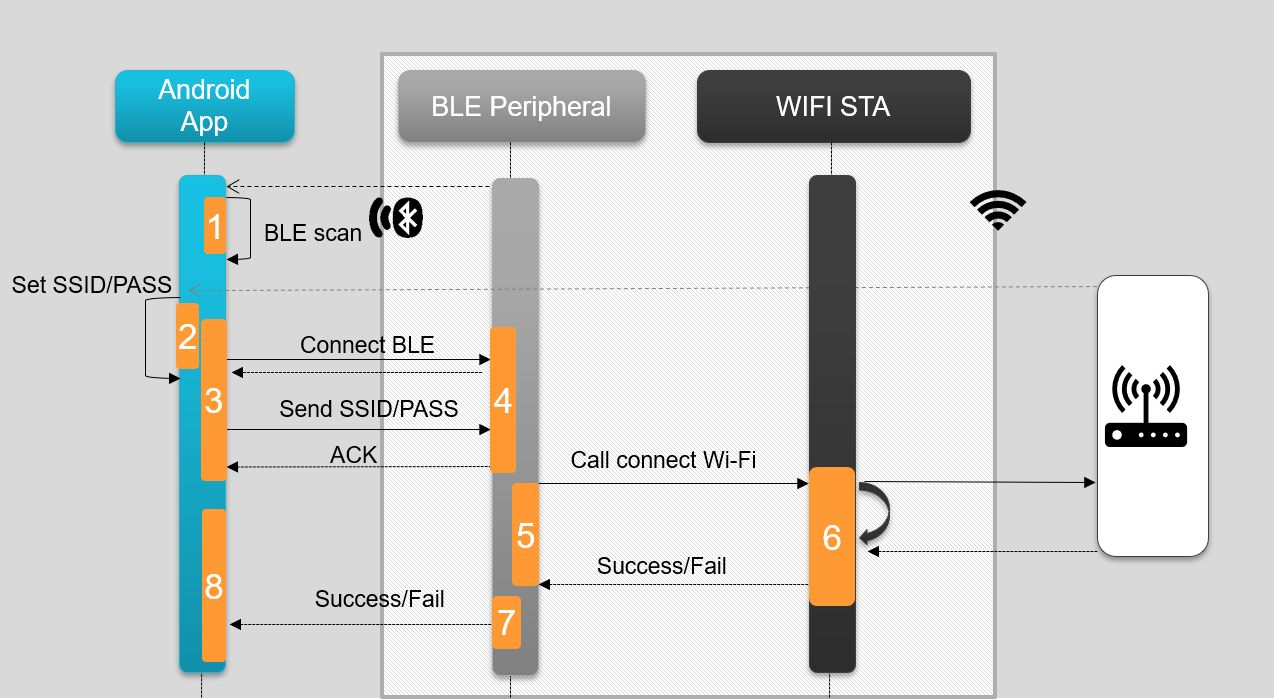
Fig. 13 Provisioning Sequence.
How to run Wi-Fi Provisioning Demo
Set up the CC33xx as explained in CC33XX Evaluation Hardware and CC33XXSoftware Download and Installation
Install the demo Android Application (APK) on an Android device. This APK is included in a separate toolbox installer
Connect the Ethernet cable to the RJ-45 jack located on BeagleBone Black. Connect the other end of the cable to a router or Ethernet switch. Check BeagleBone Black’s IP address on ethernet interface. In case IP address is not assigned automatically, assign a static IP address or use DHCP to get an IP address.
udhcpc -i eth0
Open two SSH terminals to the BeagleBone Black as the demo consists of two scripts running in parallel (BeagleBone IP comes from your PC)
ssh root@<beaglebone_ip>
Navigate both terminals to the following directory
cd /usr/share/cc33xx/wifible_provisioning_demoOn one terminal, execute the BLE provisioning script:
./provisioning_start_ble.sh
Note
It is very likely that this script will print errors, but that does not mean the program is unsuccessful. See an image below of the common errors. These errors mean that the expected programs were not previously running. Please wait a few extra seconds to see the cc33xx driver reload and BLE GATT server starting.

Fig. 14 Expected output of cc33xx_ble_enable.sh
On the other terminal, run the Wi-Fi provisioning script
./provisioning_start_wlan.sh
Launch the demo Android App and scan for BLE devices
Connect to the CC33xx BLE device. It is advertised as cc33xxble

Fig. 15 BLE scanning for cc33xxble.
Enter the Wi-Fi credentials and press Send
Note
Current version limitation: Please make sure the total length of SSID (network name) and Password is not more than 19 characters.
Finally, the Android app will print “Device connected” similar to below indicating that the Android device successfully connected to the CC33xx transceiver.
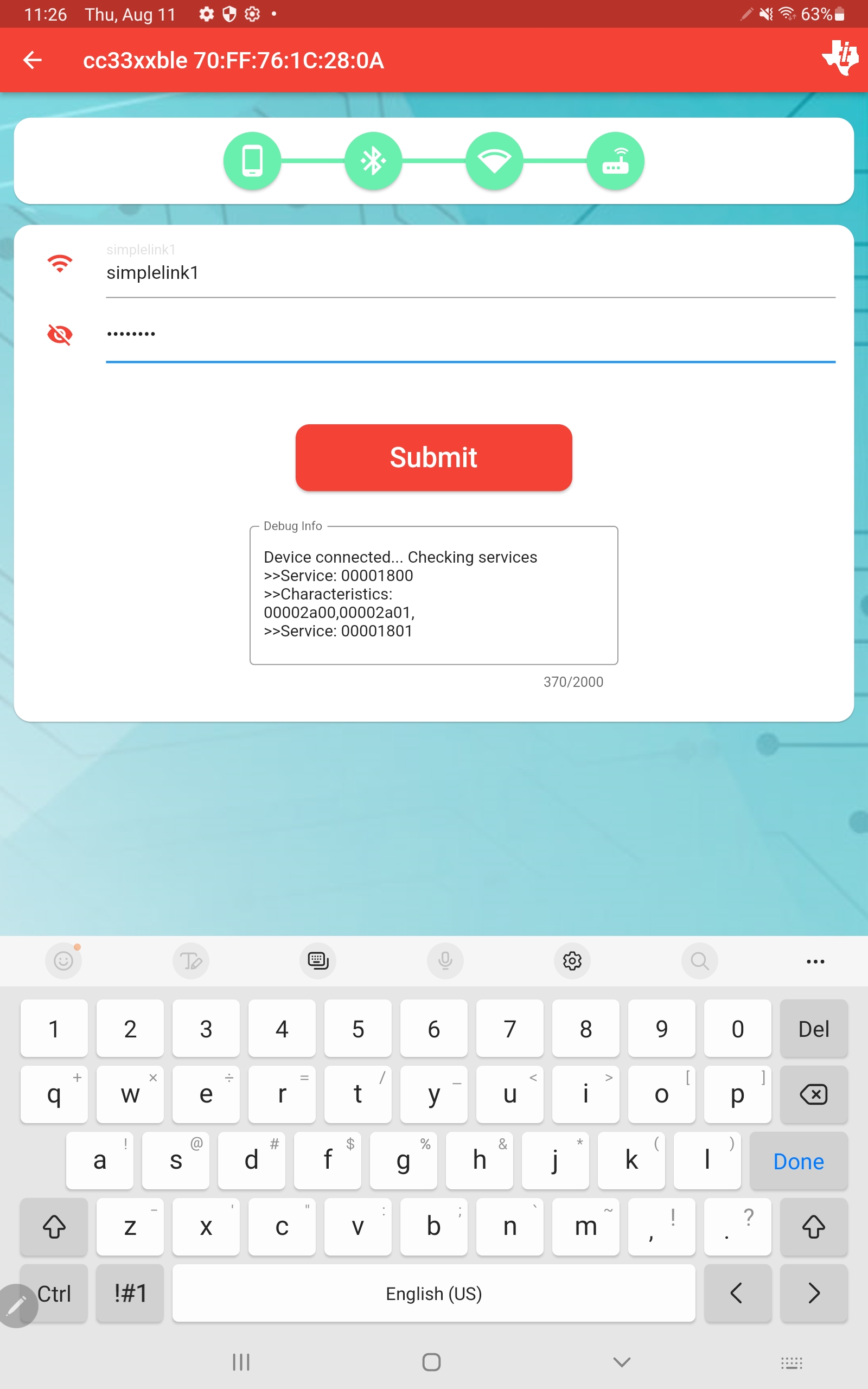
Fig. 16 Successful BLE connection and transmission.
Matter Over Wi-Fi
Overview
In this section, a CC33xx paired with a Linux host processor is set up to run Matter over Wi-Fi. This setup demonstrates how the CC33xx + a Linux host can act as a Matter controller for end devices such as smart door locks, lights, and thermostats.
This page provides the steps to
- Add Matter to the AM62x processor SDK with Yocto to enable Matter over Wi-Fi on the CC33xx.
- Build Matter on the AM62x processor with CC33xx on Debian-based Linux distributions.
- Run Matter examples with the CC33xx.
Building Matter
Note
These steps should work for most Embedded Linux Yocto platforms. If you are using another distribution, please submit a question on E2E.
Attention
Basic knowledge of Yocto is needed for this guide. More info can be found in the Yocto user manual
Adding and Building the Matter SDK with Yocto
Note
This follows Building the SDK with Yocto to build an image (Section 1.2.3.2) with some added steps to add Matter to your image.
On a Linux host machine, download the processor SDK from the PROCESSOR-SDK-AM62X downloads page.
Next, clone the tisdk repository and set up the environment using the following commands:
# clone the repository and name it tisdk
git clone https://git.ti.com/git/arago-project/oe-layersetup.git tisdk

# change directory to tisdk
cd tisdk

# configure the meta layers
./oe-layertool-setup.sh -f configs/processor-sdk/processor-sdk-scarthgap-10.01.10.04-config.txt
Two recipes are needed to build Matter – one for the matter repository and one for the zap repository. Create a matter folder that contains these recipe files.
Learn more about ZAP in the CHIP Tool documentation and in the ZAP repository.
In directory
tisdk: Navigate tosources/meta-arago/meta-arago-demos/recipes-apps.# change directory to recipes-apps cd sources/meta-arago/meta-arago-demos/recipes-apps
Create a new folder within
recipes-appsand name itmatter.# make new directory named matter mkdir matter # change directory to matter cd matter
Within this matter folder, use a text editor to create two new files named
matter_git.bbandzap_git.bb.Copy and paste in the code for these recipes which are located in Appendix A.
Enable building these BitBake recipes by including them in the
IMAGE_INSTALL. This can be done one of two ways:Option 1: Add matter to the local conf file.Navigate to
tisdk/build/confand open thelocal.conffile.Edit this file to add this line anywhere in the file:
# Add matter
IMAGE_INSTALL:append = "matter"
Save the file.
Option 2: Addmatterto thetisdk-default-image.bbrecipe.Navigate to the
meta-aragodirectory: From here, navigate tometa-arago-distro/recipes-core/imagesand open thetisdk-default-image.bbfile.Inside
IMAGE_INSTALL += "\there is a list of TI package groups and other TI-related applications (packagegroup-arago-base. ti-test, etc.). Edit this to addmatter:IMAGE_INSTALL += "\ packagegroup-arago-base \ packagegroup-arago-console \ ti-test \ ti-test-extras \ ... +matter \Save the file.
Navigate to
sources/meta-ti/meta-ti-bsp/recipes-kernel/linux/linux-ti-staging-6.6. In this directory, create and add the patch file0001-Add-WEXT-config.patch(code located in Appendix A).Navigate back one directory to
recipes-kernel/linux. Open thelinux-ti-staging_6.6.bbBitBake recipe file. Add the patch file to the BitBake recipelinux-ti-staging_6.6.bbunder the following lines:# Look in the generic major.minor directory for files FILESEXTRAPATHS:prepend := "${THISDIR}/${PN}-6.6:" +SRC_URI += file://0001-Add-WEXT-config.patch # add the patch file to the BitBake recipeSave the file.
Build the image.
# change directory to build
cd tisdk/build

# set the environment
. conf/setenv

# build the tisdk-default-image
MACHINE=<machine> bitbake -k tisdk-default-image
Note
<machine> can be set to am62xx-evm, for example. See here for additional build options if using a different processor.
The newly built WIC image will be generated in the deploy-ti directory. Flash this image to an SD card.
Note
These steps should work for most Embedded Linux Debian platforms. If you are using another distribution, please submit a question on E2E.
Building Matter with Debian
Hardware Requirements
- 1 SK-AM62B-P1
- 1 M2-CC3351
- USB-C Power supply
- microUSB cable
- 64GB SD card
Building Matter
Warning
Building Matter is very time and memory consuming. A 64GB SD card was used and building was done over ethernet with internet.
Check out the Matter top level repository.
git clone --depth=1 git@github.com:project-chip/connectedhomeip.git
Check out third-party platform supports repositories:
./scripts/checkout_submodules.py --shallow --platform linux
Install prerequisites on Linux to satisfy dependencies.
sudo apt-get install git gcc g++ pkg-config libssl-dev libdbus-1-dev \
libglib2.0-dev libavahi-client-dev ninja-build python3-venv python3-dev \
python3-pip unzip libgirepository1.0-dev libcairo2-dev libreadline-dev \
default-jre
Run the environment setup sript before running any build commands. This script downloads GN and ninja, and sets up a Python environment with libraries used to build and test.
source scripts/activate.shNote
If the script says the environment is out of date, you can update it by running this command:
source scripts/bootstrap.shBuild all sources, libraries, and tests for the host platform.
gn gen out/host

ninja -C out/host
Once Matter builds, try building the CHIP Tool in the
connectedhomeipdirectory../scripts/examples/gn_build_example.sh examples/chip-tool <BUILD_PATH>
Run CHIP Tool!
./chip-tool
The output should look like this:
root@am62xx-evm:~# chip-tool
[8574.472549][1072:1072] CHIP:TOO: Missing cluster or command set name
Usage:
chip-tool cluster_name command_name [param1 param2 ...]
or:
chip-tool command_set_name command_name [param1 param2 ...]

+-------------------------------------------------------------------------------------+
| Clusters:                                                                           |
+-------------------------------------------------------------------------------------+
| * accesscontrol                                                                     |
| * accountlogin                                                                      |
| * actions                                                                           |
| * activatedcarbonfiltermonitoring                                                   |
| * administratorcommissioning                                                        |
| * airquality                                                                        |
| * applicationbasic                                                                  |
| * applicationlauncher                                                               |
| * audiooutput                                                                       |
| * ballastconfiguration                                                              |
+-------------------------------------------------------------------------------------+
This confirms that chip-tool has been successfully built and can be used to control a Matter end device!
How to Run the Matter Example Applications
Refer to the CC33XX Getting Started with SK-AM62B-P1 and Processor SDK Linux for AM62x documentation to set up the evaluation hardware and enable Wi-Fi.
Note
Instead of flashing the pre-built tisdk-default-image-am62xx-evm.wic.xz image file to an SD card, flash the WIC image from the previous Adding and Building the Matter SDK on Yocto section.
For this example, two identical setups are used:
- SK-AM62B-P1 connected via Wi-Fi with the M2-CC3351 facilitating communication using the Matter protocol.
One AM62x MPU will serve as the administrator / CHIP tool, while the other will function as an endpoint.

Matter Examples
Set up one AM62B as an administrator running CHIP tool. To commission into a network over IP, allow the administrator to discover the endpoint device.
chip-tool pairing onnetwork 1 20202021 –-bypass-attestation-verifier true
Set up the other AM62B as a Matter end device. For example, a Matter door lock or a Matter lighting app.
The door lock cluster:
chip-lock-appThe lighting cluster:
chip-lighting-app
Once the administrator identifies and pairs with the endpoint, the two devices will begin communicating with each other. Once the device has been successfully commissioned, the following messages will show on the CHIP tool output:
[169.529678][960:962] CHIP:TOO: Discovered Device: fe80::1e63:49ff:fe22:4f5c:5540
[169.882592][960:962] CHIP:TOO: Pairing Success
[172.633376][960:962] CHIP:CTL: Commissioning complete for node ID 0x0000000000000001: success
[172.633390][960:962] CHIP:TOO: Device commissioning completed with success
On the end device / commissioned device, the output will show the message:
[34.071874][941:941] CHIP:SVR: Commissioning completed successfully
Example Commands
- Refer to the Matter Lock Example Application in the Matter repository.
- Refer to the Matter Lighting Example Application in the Matter repository.
Appendix A
- matter_git.bb
SUMMARY = "Matter IoT connectivity on TI boards"
DESCRIPTION = "This recipe primes the matter environment"
LICENSE = "Apache-2.0"
LIC_FILES_CHKSUM = "file://${COMMON_LICENSE_DIR}/Apache-2.0;md5=89aea4e17d99a7cacdbeed46a0096b10"

BRANCH = "v1.3-branch"
SRC_URI = "gitsm://github.com/project-chip/connectedhomeip.git;protocol=https;branch=${BRANCH};lfs=1"

SRCREV = "5524d5b5713efbb39273f56067a3845a08ce826d"


do_matter_bootstrap[network] = "1"
do_compile[network] = "1"

TARGET_CC_ARCH += "${LDFLAGS}"
DEPENDS += " glib-2.0 gn-native ninja-native avahi dbus-glib-native pkgconfig-native python3-native boost zap-native openssl-native ca-certificates-native clang-native"
RDEPENDS_${PN} += " libavahi-client openssl "
FILES:${PN} += "usr/share"

INSANE_SKIP:${PN} += "dev-so debug-deps strip"

PACKAGECONFIG ?= ""
PACKAGECONFIG[debug] = "is_debug=true,is_debug=false"

inherit pkgconfig

GN_TARGET_ARCH_NAME:aarch64 = "arm64"
GN_TARGET_ARCH_NAME:arm = "arm"
GN_TARGET_ARCH_NAME:x86 = "x86"
GN_TARGET_ARCH_NAME:x86-64 = "x64"


def gn_target_arch_name(d):
        """Returns a GN architecture name corresponding to the target machine's
        architecture."""
        name = d.getVar("GN_TARGET_ARCH_NAME")
        if name is None:
                bb.fatal('Unsupported target architecture. A valid override for the '
                                'GN_TARGET_ARCH_NAME variable could not be found.')
        return name

# this variable must use spaces and double quotes for parameter strings because
# *gn* is evil
GN_ARGS = " \
        ${PACKAGECONFIG_CONFARGS} \
        target_cpu="${@gn_target_arch_name(d)}" \
        target_arch="${TUNE_FEATURES}" \
        target_os="linux" \
        treat_warnings_as_errors=false \
        enable_rtti=true \
        enable_exceptions=true \
"

# Make sure pkg-config, when used with the host's toolchain to build the
# binaries we need to run on the host, uses the right pkg-config to avoid
# passing include directories belonging to the target.
GN_ARGS += 'host_pkg_config="pkg-config-native"'

S = "${WORKDIR}/git"

common_configure() {
        # this block must use spaces and double quotes for strings because *gn* is
        # evil
        PKG_CONFIG_SYSROOT_DIR=${PKG_CONFIG_SYSROOT_DIR} \
        PKG_CONFIG_LIBDIR=${PKG_CONFIG_PATH} \
        gn gen out/ --args='
                ${GN_ARGS}
                import("//build_overrides/build.gni")
                target_cflags=[
                        "-DCHIP_DEVICE_CONFIG_WIFI_STATION_IF_NAME=\"wlan0\"",
                        "-DCHIP_DEVICE_CONFIG_LINUX_DHCPC_CMD=\"udhcpc -b -i %s \"",
                ]
                custom_toolchain="${build_root}/toolchain/custom"
                target_cc="${CC}"
                target_cxx="${CXX}"
                target_ar="${AR}"
        '
}

export https_proxy
export http_proxy
export ftp_proxy
export no_proxy

do_matter_bootstrap() {
        cd "${S}"
        . ${S}/scripts/bootstrap.sh
}

do_configure() {
        . scripts/activate.sh
        pip install click

        cd ${S}/examples/chip-tool
        common_configure

        cd ${S}/examples/lock-app/linux
        common_configure

        cd ${S}/examples/thermostat/linux
        common_configure

        cd ${S}/examples/lighting-app/linux
        common_configure
}

do_compile() {
        . scripts/activate.sh

        cd ${S}/examples/chip-tool
        ninja -C out/

        cd ${S}/examples/lock-app/linux
        ninja -C out/

        cd ${S}/examples/thermostat/linux
        ninja -C out/

        cd ${S}/examples/lighting-app/linux
        ninja -C out/
}

do_install() {
        install -d -m 755 ${D}${bindir}

        # Install chip-tool
        install ${S}/examples/chip-tool/out/chip-tool ${D}${bindir}

        # lock-app
        install ${S}/examples/lock-app/linux/out/chip-lock-app ${D}${bindir}
        install ${S}/examples/thermostat/linux/out/thermostat-app ${D}${bindir}
        install ${S}/examples/lighting-app/linux/out/chip-lighting-app ${D}${bindir}
}

addtask matter_bootstrap after do_unpack before do_configure

INSANE_SKIP_${PN} = "ldflags"
- zap_git.bb
PN = "zap-native"
SUMMARY = "ZAP prebuilt tools"
DESCRIPTION = "ZAP prebuilt binaries"
LICENSE = "Apache-2.0"
LIC_FILES_CHKSUM = "file://${COMMON_LICENSE_DIR}/Apache-2.0;md5=89aea4e17d99a7cacdbeed46a0096b10"

PACKAGES = "${PN}"

PV = "v2023.08.04-nightly"
SRC_URI = "https://github.com/project-chip/zap/releases/download/${PV}/zap-linux-x64.zip;unpack=yes"
SRC_URI[sha256sum] = "b254a0c066ef6b1fe7c2bdd1ab5b137ca80413f0952dfe6e64f4b0fdc4479b55"

S = "${WORKDIR}"

#INSANE_SKIP:${PN} = " already-stripped arch file-rdeps "
BBCLASSEXTEND = "native"
INHIBIT_PACKAGE_STRIP = "1"
INHIBIT_SYSROOT_STRIP = "1"
INHIBIT_PACKAGE_DEBUG_SPLIT = "1"
INHIBIT_FILE_RDEPS = "1"
INHIBIT_PACKAGE_DEBUG_SPLIT_CHECK = "1"
INHIBIT_PACKAGE_DEPMODE_CHECK = "1"
INHIBIT_PACKAGE_RELOCATE = "1"
INHIBIT_PACKAGE_UNPACK = "1"

INSANE_SKIP:${PN} += "dev-so"
inherit native

do_install() {
        install -d -m 0755 ${D}${bindir}/
        cp -ar zap* ${D}${bindir}/
        # This is a workaround to bypass the issue that zap-cli modified by build system
        chmod 444 ${D}${bindir}/zap-cli
}

do_package_qa[noexec] = "1"
EXCLUDE_FROM_SHLIBS = "1"

# This is a workaround to bypass the issue that zap-cli modified by build system
do_deploy() {
        chmod 755 ${D}${bindir}/zap-cli
}

do_populate_sdk:append() {
        chmod 755 ${D}${bindir}/zap-cli
}

addtask deploy after do_install do_populate_sysroot
addtask deploy before do_cleansstate
addtask deploy before do_clean
- 0001-Add-WEXT-config.patch
From 761f927e043fd4486299d23868062a9923bcf17b Mon Sep 17 00:00:00 2001
From: Sabeeh Khan <sabeeh-khan@ti.com>
Date: Mon, 24 Feb 2025 14:06:10 -0600
Subject: [PATCH] Add WEXT config

---
arch/arm64/configs/defconfig | 1 +
1 file changed, 1 insertion(+)

diff --git a/arch/arm64/configs/defconfig b/arch/arm64/configs/defconfig
index 89882a926105..f9c290e38f9d 100644
--- a/arch/arm64/configs/defconfig
+++ b/arch/arm64/configs/defconfig
@@ -471,6 +471,7 @@ CONFIG_RSI_91X=m
CONFIG_WL18XX=m
CONFIG_CC33XX=m
CONFIG_CC33XX_SDIO=m
+CONFIG_CFG80211_WEXT=y
CONFIG_WLCORE_SDIO=m
CONFIG_WWAN=m
CONFIG_MHI_WWAN_CTRL=m
--
2.34.1