CPU Timers#
The C2000 family of devices have many 32-bit CPU Timers. This section describes the three 32-bit CPU timers (TIMER 0/1/2) shown in figure below.
Timer0 and Timer1 can be used in user applications. Timer2 is reserved for real-time operating system uses (for example, TI-RTOS). If the application is not using an operating system that utilizes this timer, then Timer2 can be used in the application.
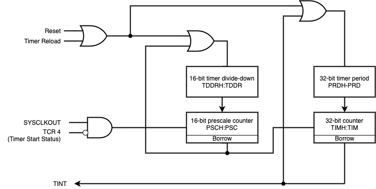
The general operation of a CPU timer is as follows:
The 32-bit counter register, TIMH:TIM, is loaded with the value in the period register PRDH:PRD
The counter decrements once every (TPR[TDDRH:TDDR]+1) SYSCLK cycles, where TDDRH:TDDR is the timer divider.
When the counter reaches 0, a timer interrupt output signal generates an interrupt pulse.
Watchdog Timer#
The watchdog timer is a safety feature, which resets the device in case of “run away” code or if The code gets trapped in an unintended infinite loop. The watchdog counter runs independent of the CPU. If the counter overflows, a user-selectable reset or interrupt is triggered. During runtime the correct key values in the proper sequence must be written to the watchdog key register in order to reset the counter before it overflows.
The watchdog timer provides a safeguard against CPU crashes by automatically initiating a reset if it is not serviced by the CPU at regular intervals. In motor control applications, this helps protect the motor and drive electronics when control is lost due to a CPU lockup. Any CPU reset will set the PWM outputs to a high-impedance state, which should turn off the power converters in a properly designed system.
The watchdog timer starts running immediately after system power-up/reset, and must be dealt with by software soon after. Specifically, the watchdog must be serviced or disabled within 13.11 milliseconds (using a 10 MHz watchdog clock) after any reset before a watchdog initiated reset will occur. This translates into 131,072 watchdog clock cycles, which is a seemingly tremendous amount! Indeed, this is plenty of time to get the watchdog configured as desired and serviced. A failure of your software to properly handle the watchdog after reset could cause an endless cycle of watchdog initiated resets to occur.
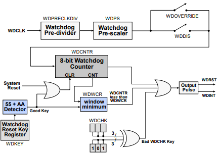
In the figure above, the F2807x and F2837xD/S devices do not have a watchdog pre-divider (it is fixed at /512)
The watchdog clock is divided and prescaled, if desired, for slower watchdog time periods. A watchdog disable switch allows the watchdog to be enabled and disabled. Also a watchdog override switch provides an additional safety mechanism to insure the watchdog cannot be disabled. Once set, the only means to disable the watchdog is by a system reset.
During initialization, a value ‘101’ is written into the watchdog check bit fields. Any other values will cause a reset or interrupt. During run time, the correct keys must be written into the watchdog key register before the watchdog counter overflows and issues a reset or interrupt. Issuing a reset or interrupt is user-selectable. The watchdog also contains an optional “windowing” feature that requires a minimum delay between counter resets.
Feedback
Please provide any feedback you may have about the content within C2000 Academy to: c2000_academy_feedback@list.ti.com