Getting Started with CCS#
The objective of this lab is to get started with TI’s Code Composer Studio (CCS) development environment by running a basic example on your C2000 device to toggle an LED on the board. The lab exercise demonstrates how to import a project from a C2000Ware DriverLib example, rename the project, and modify the code. It also illustrates the minimum steps required to toggle an LED GPIO, compile your code, build the output, and run the generated-out file on your target EVM device (a LaunchPad or controlCARD).
Refer to our Getting Started with CCS and C2000Ware video for a demonstration on how to utilize CCS and C2000Ware.
Solution#
All C2000 Academy lab software solutions are located in the directory: [C2000Ware_Install_Path]/training/device/[device_name].
Lab Setup#
Hardware Setup#
This lab exercise is intended for LaunchPad and controlCARD C2000 devices:
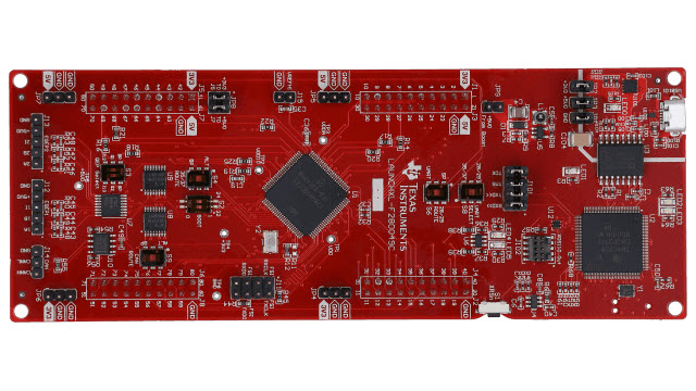
LaunchPad
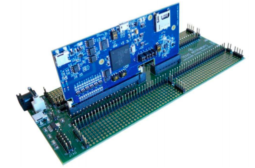
controlCARD
Using the supplied USB cable, connect the USB Micro or Mini Type-B connector into your C2000 board and the USB Standard Type-A connector into your computer’s USB port (please note that controlCARD docking stations may require an additional power supply connection). You should see some LEDs light up on the board. This connection will power the board and provide a JTAG communication link between your device and CCS.
Software Setup#
The following software and tools are required to run these labs on C2000 microcontrollers:
TI’s Code Composer Studio (CCS) An Integrated Development Environment (IDE) for development of code for the C2000 family of devices
C2000Ware Software Development Kit (SDK) An SDK including low level drivers, highly optimized libraries, and software examples to start using the C2000 family of devices.
Start a CCS Environment#
Open a Workspace#
Start Code Composer Studio (CCS) by double clicking the icon on the desktop or selecting it from the Windows ‘Start’ menu. When CCS loads, a dialog box will prompt you for the location of a workspace folder. Use the default location for the workspace and click ‘Launch’. This workspace folder will contain all CCS custom settings. This includes project settings and views when CCS is closed so that the same projects and settings will be available when CCS is opened again. The workspace is saved automatically when CCS is closed.
The first time CCS opens, an introduction page appears. Close the page by clicking the ‘X’ on the ‘Getting Started’ tab. You should now have an empty workbench. The term ‘workbench’ refers to the desktop development environment. Maximize CCS to fill your screen. The workbench will open in the ‘CCS Edit’ perspective view. Notice the ‘CCS Edit’ icon in the upper right-hand corner. A perspective defines the initial layout views of the workbench windows, toolbars, and menus which are appropriate for a specific type of task (i.e., code development or debugging). This minimizes clutter to the user interface. The ‘CCS Edit’ perspective is used to create or build C/C++ projects. A ‘CCS Debug’ perspective view will automatically be enabled when a debug session is started. This perspective is used for debugging C/C++ projects.
Import an Empty Project#
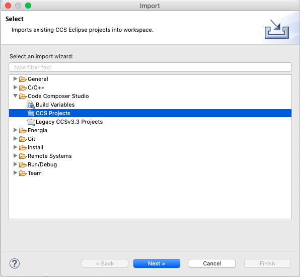
Import an empty project from the C2000Ware DriverLib examples. Go to CCS and navigate to File → Import…
Click the ‘Browse…’ button
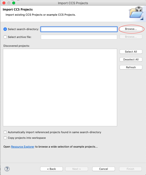
Go to
[C2000ware Install_dir]/driverlib/[device]/examples/empty_projects. The default install folder in Windows isC:/ti/C2000Ware_X_XX_00_00. For correct device name, check your board LaunchPad, or controlCARD. For dual core devices, look in the[C2000Ware Install_dir]/driverlib/[device]/cpu1/empty_projectsdirectory.
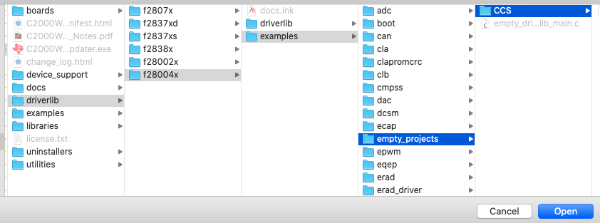
Click the ‘Open’ button. This should list the project like below.
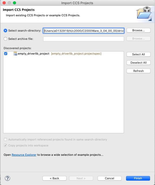
Click the ‘Finish’ button.
Right-click on the project in ‘Project Explorer’ panel. Click ‘Rename’ and rename the project to a name that you would like. For this example, we will use ‘ex’. If you have multiple projects in your workspace related to the same thing (i.e. labs or software examples) you can add a prefix to your project’s title so that all projects are grouped together.
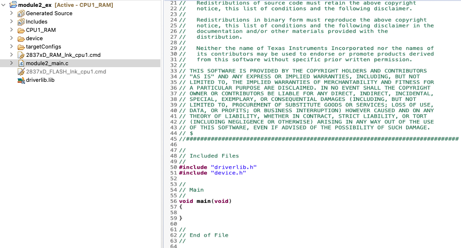
Now click the down arrow located to the left of the imported project to expand it, and select the ‘empty_projects_main.c’ file. Right-click on the file and select ‘Rename’ to rename the file to something you would like. For this example we will use ‘ex_main.c’.
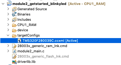
Open ‘ex_main.c’ by double-clicking on the file. Now the workspace should look like below:
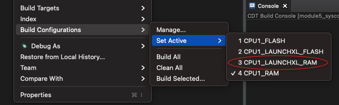
If you are working with LaunchPad, then select the CPU1_LAUNCHXL_RAM build configuration from the menu. Right-click on project for the menu.
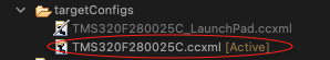
When debugging, make sure the correct target configuration file (‘.ccxml’ file) is ‘Active’ for your board.
Right-click on the project and select ‘Rebuild’. It should build with 0 errors in the ‘Console Output’ window.
Project Build Options#
There are numerous build options in the project. Most default option settings are sufficient for getting started. We will inspect a couple of the default options at this time. Right-click on project name in the ‘Project Explorer’ panel and select ‘Properties’ or go to Project → Properties
A ‘Properties’ window will open and in the section on the left under ‘Build’, be sure that the ‘C2000 Compiler’ and ‘C2000 Linker’ options are visible. Next, under ‘C2000 Linker’, select the ‘Basic Options’ tab. Notice that ‘.out’ and ‘.map’ files are being specified. The ‘.out’ file is the file that will contain the executable code to be loaded into the microcontroller. The ‘.map’ file will contain a linker report showing memory usage and memory section addresses. Also notice the stack size.
Under ‘C2000 Compiler’ select the ‘Processor Options’. Notice the large memory model and unified memory boxes are checked. Next, notice ‘Specify CLA support’ is set to ‘cla1’ or ‘cla2’, ‘Specify floating point support’ is set to ‘fpu32’, ‘Specify TMU support’ is set to ‘TMU0’, and ‘Specify VCU support’ is set to ‘vcu0’ or ‘vcu1’. Select ‘Apply and Close’ to close the ‘Properties’ window. Refer to C2000 Peripheral Guide for details on the types of CLA and VCU supported on your device.
Linker Command File#
Open and inspect the
[device]_generic_ram_link.cmdfile by double clicking on the filename in the ‘Project Explorer’ window. Notice that the Memory{} declaration describes the system memory. Notice the blocks of memory that have been placed in the.textsection. This is where the program data resides. Additionally, note the blocks of memory that have been assigned to other sections such as.ebss,.cinit, and.stack. These sections are needed for the C compiler and contain various data memory.In the Sections{} area, notice that the sections defined on the slide have been “linked” into the appropriate memories. Also, notice that a section called ‘.reset’ has been allocated. The ‘.reset’ section is part of the ‘rts2800_fpu32.lib’ and is not needed. By putting the “TYPE = DSECT” modifier after its allocation, the linker will ignore this section and not allocate it. Close the inspected file.
Build and Load the Project#
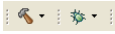
Two buttons on the horizontal toolbar control code generation. Hover your mouse over each button (seen below) as you read the following descriptions.
Name |
Description |
|---|---|
“Build” |
Full build and link of all source files |
“Debug” |
Automatically build, link, load and launch debug-session |
Set Up Target Configuration#
Option 1: Using ‘Active’ target configuration#
In the ‘Project Explorer’ panel, open [project name] → targetConfigs and make sure the ‘TMS320F28XXXX.ccxml’ is set as ‘Active’. See below for reference.
Start debugging the code by navigating to Run → Debug. It will automatically launch the target configuration, connect to the CPU, and load the ‘.out’ file of executable code.
Option 2: Manually launching target configuration#
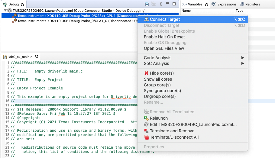
Open the target configuration dialog box. On the menu bar, click View → Target Configurations and click the sign (‘+’ or ‘>’) to the left of “Projects”. Notice that the [device_board].ccxml file is listed. Select the ‘.ccxml’ file, right-click on it, and select ‘Launch Selected Configuration’.
In the debug window that pops up, select the ‘C28xx_CPU1’ row, right-click on it, and select ‘Connect Target’.
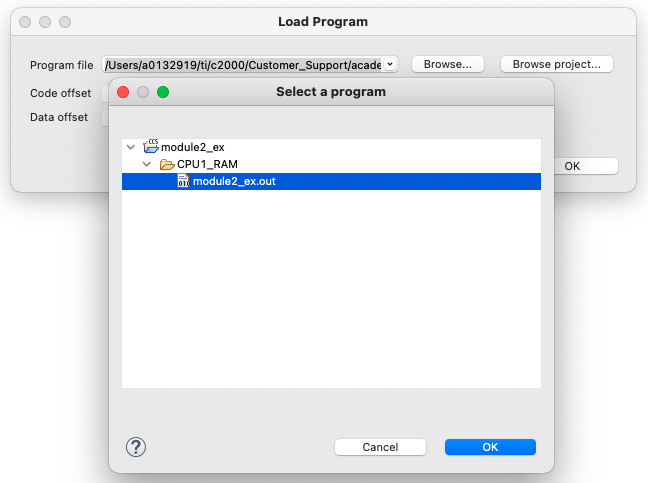
Navigate to Run → Load → Load Program and click on the ‘Browse project…’ button and select ex → CPU1_RAM or LAUNCHXL_CPU1_RAM → ex.out. Click the ‘Ok’ button
Program the LED Toggle#
The minimum steps required to configure the target and toggle an LED are listed below. For this lab exercise, we will use the C2000Ware DriverLib application programming interface (API). Open the ‘main.c’ file by double-clicking the file in ‘Project Explorer’ panel.
Copy following code in main() function to initialize the device clock and peripheral for the device.
// Device Initialization
Device_init();
Copy following code to initialize the LED GPIO pin and configure the GPIO pin as a push-pull output
// Initialize GPIO and configure the GPIO pin as a push-pull output
Device_initGPIO();
GPIO_setPadConfig(DEVICE_GPIO_PIN_LED1, GPIO_PIN_TYPE_STD);
GPIO_setDirectionMode(DEVICE_GPIO_PIN_LED1, GPIO_DIR_MODE_OUT);
Now configure interrupt controller and interrupt service routines by copying following code in.
// Initialize PIE and clear PIE registers. Disables CPU interrupts.
Interrupt_initModule();
// Initialize the PIE vector table
Interrupt_initVectorTable();
// Enable Global Interrupt (INTM) and realtime interrupt (DBGM)
EINT;
ERTM;
Copy the code in below to create an infinite loop the will toggle the LED GPIO with some delay. The frequency of toggle can be controlled through the delay parameter.
// Loop Forever
for(;;)
{
    // Turn on LED
    GPIO_writePin(DEVICE_GPIO_PIN_LED1, 0);
    // Delay for a bit.
    DEVICE_DELAY_US(500000);
    // Turn off LED
    GPIO_writePin(DEVICE_GPIO_PIN_LED1, 1);
    // Delay for a bit.
    DEVICE_DELAY_US(500000);
}
Right-click the project and rebuild the project. Navigate to Run → Debug to load and run the code on target.
Terminate the debug session using the red square stop button, and close the project. This concludes the lab assignment.
Full Solution#
The full solution to this lab exercise is included as part of the C2000Ware
SDK. You can import this solution project from the directory:
<c2000ware_install_path>/training/device/<device_name>/getting_started/lab_binkyled_driverlib.
Using the CCS Graph Tool#
CCS perspective is a collection of windows, layouts, views, and toolbars in the CCS workspace
window. By default, CCS opens in CCS Edit perspective and when you are debugging, it automatically
switches to CCS Debug perspective.
Lab exercises of many subsequent modules need CCS graphing tools to view the plots and validate the results.
If you are using CCS debug perspective, then CCS menu Tools → Graph is available by-default and
no configuration is required.
If you are using CCS Simple perspective, then CCS menu Tools → Graph is not available by-default.
You can customize the CCS Simple perspective to add graphing tools. Steps required as listed below:
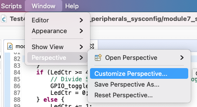
Open CCS menu Window → Perspective → Customize Perspective…
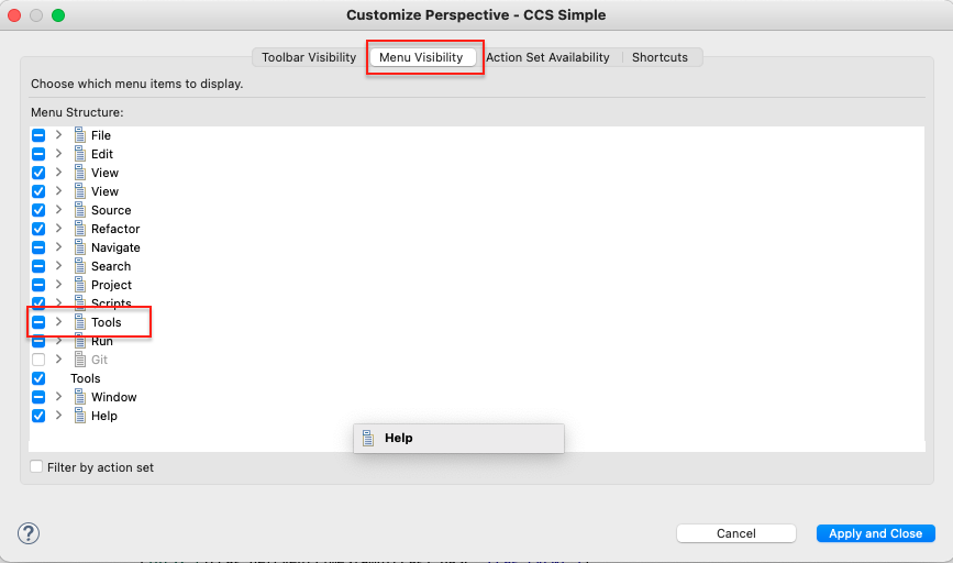
Open tab
Menu Availabilityand checkTools
Open tab
Action Set Availabilityand checkGraph
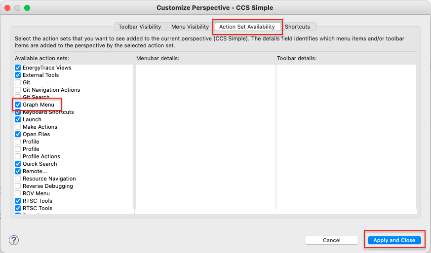
Press
Apply and Closebutton. The tools and graph menu will be available now. This is only one-time configuration and CCS will remember the configuration for the workspace even after closing it.
Feedback
Please provide any feedback you may have about the content within C2000 Academy to: c2000_academy_feedback@list.ti.com